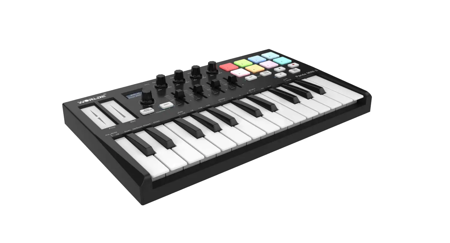
WORLDE PANDAMINI II Midi Controller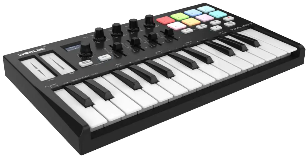
Introduction
Thank you for purchasing the WORLDE PANDAMINI II USB MIDI controller. PANDAMINI II is a high quality, feature-packed controller which includes all the essentials to start making music. To help you get the most out of your new instrument, please read this manual carefully.
Your PANDAMINI II midi controller will not make any sound unless it is connected to a computer or other external MIDI gear. This is because the PANDAMINI II sends MIDI data when you play it and does not produce sound on its own. Instead, it is used to control a virtual instrument on your computer or a MIDI sound module to generate sounds.
In order to use the functions of this product, you’ll need to make settings in the application you’re using. Make settings as described in the owner’s manual for your application.
PANDAMINI II integrates perfectly with DAWs (such as Ableton Live, Bitwig and so on) for both production and performance. You can navigate and control Live’s Session View, play and record clips, adjust effects and much more without ever looking at your computer.
PANDAMINI II’s pads bring your Ableton Session to your fingertips in full RGB colour, so you know exactly which clips you’re launching.
Also, you can make PANDAMINI II the perfect controller for your studio under common mode, where you can customise knobs,sliders and pads using the MENU button.
PANDAMINI II also has a standard 3.5mm TRS MIDI Out jack for connecting to your hardware synths and drum machines. This means you can use many of the PANDAMINI II’s functions without a computer.
Features
- 8 high quality velocity & pressure sensitive performance pads with RGB backlit, can be assigned easily as pads, MIDI notes.
- 25 velocity sensitive mini-keys, with 3 velocity curve and one constant velocity.
- 4 Assignable rotary knobs, each can be edited by user.
- 4 Assignable sliders, each can be edited by user.
- Brilliant OLED display for immediate parameter setting.
- 2 touch sensors of dynamic pitch bend and modulation touch strips.
- Standard sustain pedal jack, compatible with switch pedal.
- Fixed Chord mode.
- 1xValue Dial(Enter button:push to enter).
- Play and record transport control buttons.
- Powerful and creative Arpeggiator for generating ideas quickly.
- Custom modes for user-defined mappings of knobs,sliders and pads.
- USB interface, adaptable to USB 2.0(FULL SPEED).
- Connect to your hardware with a standard 3.5mm TRS MIDI Out jack.
- Power supplied by USB.
- Compatible with Win XP/7/8/10/Vista and Mac OSX.
- Compatible with iOS by using the Apple iPad Camera Connection Kit(sold separately).
- Drive free and hot-plug supported.
- Ableton Live integration – Launch clips and scenes, play instruments and Drum Racks, capture MIDI, and more.
- Integration with other DAWs (Apple Logic Pro X, Propellerhead’s Reason, etc.).
Getting Started
WORLDE PANDAMINI II Keyboard Overview
Top Panel Overview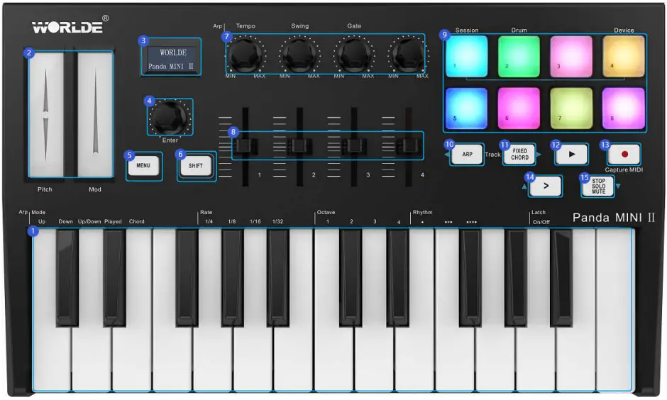
Rear Panel Overview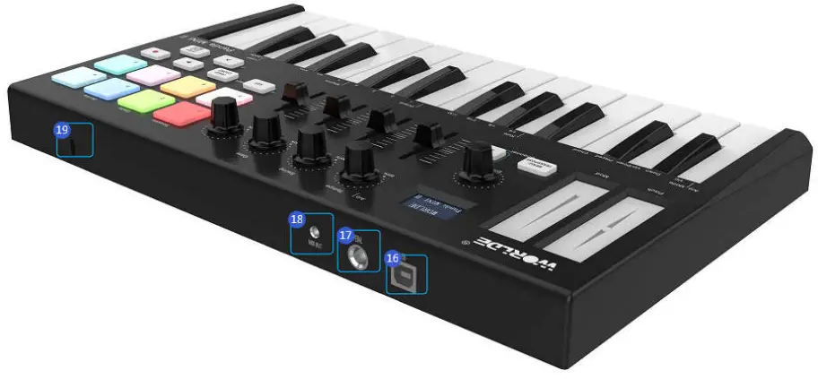
Control Definitions:
- Keyboard
- Pitch/Mod Touch strips
- OLED DISPLAY
- Value Dial(Enter button: Push to enter)
- MENU button
- SHIFT button
- Knobs
- Sliders
- rigger Pads(with RGB backlit)
- Arp button
- Fixed Chord button
- ▶Playback button
- ● Record button
- > Scene Launch button
- Stop/solo/mute button
- USB 2.0 port
- Sustain pedal
- Standard 3.5mm TRS MIDI Out jack
- Kensington Security Slot
Setup
If you intend to connect your PANDAMINI II keyboard to a computer or mobile devices, please read sections 3.2 to 3.4 first. If you only intend to use your PANDAMINI II keyboard to control a sound module or synthesizer using the external MIDI OUT you should skip to section 3.5.
Minimum System Requirements
If you are using your PANDAMINI II with a computer, the following minimum system requirements apply:
| Windows | Mac OS |
| i3 1.2GHz or higher | Macintosh i3*1.2GHz/P4*1.2GHz or higher |
| (CPU requirement may be higher for laptops) | (CPU requirement may be higher for laptops) |
| 1G RAM | OS X 10.3.9 with 1G RAM, |
| Direct X 9.0b or higher | OS X 10.4.2 or greater with 1G RAM |
| Windows XP (SP2) or higher | *G3/G4 accelerator cards are not supported. |
| (Windows 98, Me, NT or 2000 not supported) |
WORLDE suggests you also check the minimum system requirements for your software, as they may be greater than the above.
USB hubs are not supported. WORLDE suggests that you connect directly to one of your computer’s built in USB ports.
Using The PANDAMINI II With Your Software
When installed, the PANDAMINI II appears as a simple MIDI device with one input port and one output port. You should select the listed USB MIDI Controller input port as the MIDI input device in your software. Once this is set, your software should be able to receive notes and controller data from the PANDAMINI II.
The port name is defined as WORLDE when connecting to USB port.
It will appear as WORLDE in the Device Manager.
Connecting to a Computer
PANDAMINI II is bus-powered, so it turns on as soon as you connect it to your computer with a USB cable.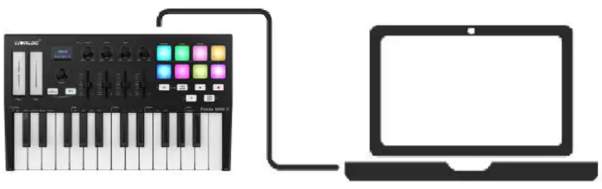
Connecting to Mobile Devices
iOS
To operate your PANDAMINI II with an iOS device, use Apple’s Lightning to USB 3 Camera Adapter with a separate 2.4A Lightning charger.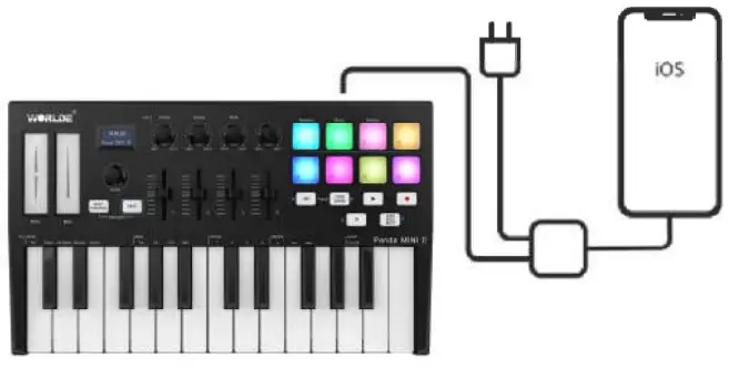
Android
To operate the PANDAMINI II with an Android device we’d like to recommend a USB OTG to USB adapter.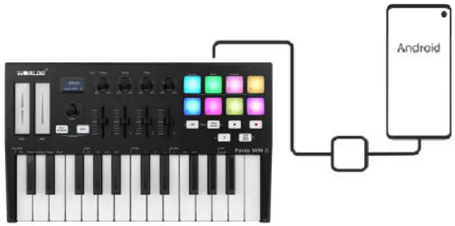
Using as a Standalone MIDI Controller
The 3.5mm TRS MIDI Out port can be used to connect the PANDAMINI II to a hardware sequencer, an external synthesizer or sound module. 3.5mm TRS MIDI Out to MIDI DIN adaptor is included.
If you want to use the 3.5mm TRS MIDI output on the PANDAMINI II without a computer, you can power the unit with a standard USB power supply (5V DC, minimum 500mA).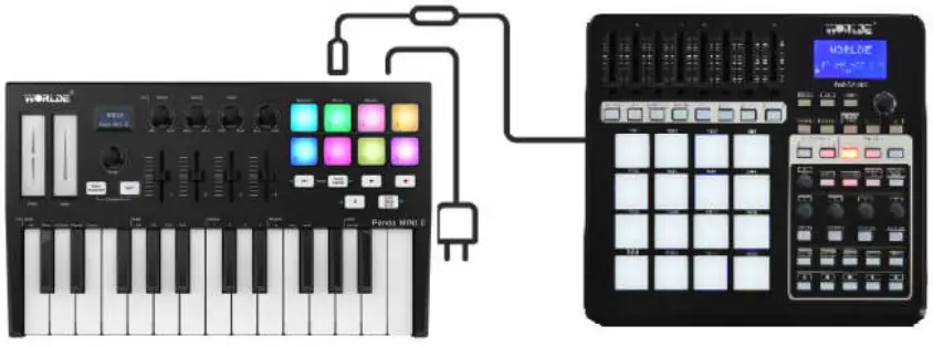
Parts and Their Functions
Keyboard
When you play the keyboard, MIDI note messages are sent. These messages are read by your computer software or external MIDI gear and used to generate sound accordingly. The sound played by the keyboard is from your computer software or external MIDI gear. With the MENU button and Value Dial it’s possible to adjust the keyboard velocity curve, octave, transpose, channel, program change etc. More details can be found in section 5.
Trigger pads
The 8 RGB Pads can transmit MIDI note messages. With the ENU button and Value Dial it’s possible to adjust the pad velocity curve, midi note number, RGB color of the pad backlight etc. More details can be found in section 5.
Knobs
The 4 knobs can transmit control change messages. It can be assigned to control any editable parameter on the selected device. More details can be found in section 5.
Sliders
The 4 sliders can transmit control change messages. It can be assigned to control any editable parameter on the selected device. More details can be found in section 5.
Pitch and Modulation touch strips
Pitch bend and modulation are activated by pressing the touch strips. If you touch the Pitch bend strip at its center and move your finger forward or backward it will alter the pitch of the played sound.
Similarly, moving your finger along the Modulation strip alters the modulation amount of the played sound.
OLED Display
OLED display is for immediate parameter setting.
Value dial(Enter button: push to enter)
This dial is used for incrementing and decrementing Presets, parameter values and settings. This dial also functions as an [ENTER] button when it is pressed down. Holding the “Enter” button for 2 seconds to exit the edit mode and return to parameter display mode. Then if you rotate the knobs, move the sliders or trigger the pads the OLED will display the current parameters of these controllers.
MENU button
Press MENU button to select the following functions of PANDAMINI II: Octave, Velocity curve, Pad velocity, Store all parameters, Recall all parameters, MIDI channel, Program change, Control assign, Transpose, Pad color R, Pad color G, Pad color B, Reset all, CC NUM/Pad note Controller value.
SHIFT button
Press Shift and other buttons at the same time to access secondary functions.
Shift is used to select the pads which are great for triggering clips in Ableton Live’s Session View and playing drums. Holding Shift button lights up the top row of pads. You can then switch between the 2 pad modes:
Session: For triggering clips and navigating Live’s Session View.
Drum: For playing drums with the velocity-sensitive pads.
Arp button
Press the Arp button to activate the Arpeggiator of the PANDAMINI II.
Fixed Chord button
While holding the Fixed Chord button, press and release the keys that you wish to be part of the stored ‘fixed’ chord. It only works when connected with Ableton Live.
▶ Playback button
This button controls your DAW’s playback.
● Record button
The Record button starts the recording process in your DAW.
> Scene Launch button
Press shift and Scene Launch button (>) launches scenes in Ableton Live. This means that all of the clips in a row can start together. It only works when connected with Ableton Live.
Stop/solo/mute button
Stop/solo/mute: Press this button to switch the functionality of the bottom 8 pads. It only works when connected with Ableton Live.
Full sized USB connector
Connect the WORLDE PANDAMINI II to your computer with a USB cable via this port.
Sustain Pedal Jack
The footswitch jack functions as sustain pedal interface.
Note: the default setting for footswitch jack is open meaning that pressing the pedal will function as sustain. If it’s without sustain function when pressed, it means that the pedal polarity is opposite, so it needs to adjust the polarity by moving the pedal polarity switch to the other end.
3.5mm TRS MIDI Out port
The 3.5mm TRS MIDI Out port can be used to connect the PANDAMINI II to a hardware sequencer, an external synthesizer or sound module. 3.5mm TRS MIDI Out to MIDI DIN adaptor is included.
Basic MIDI Control From Your PANDAMINI II
MIDI Control Messages
There are 135 MIDI controller messages that are used for controlling the MIDI adjustable parameters in your software or on your external MIDI gear (0 to127 is the standard MIDI control parameter, 128 to 134 is the special MIDI control parameter). Examples of these controllable parameters include volume, pan, expression, reverb, chorus and portamento.
The 8 assignable knobs/sliders and 8 assignable pads on your PANDAMINI II keyboard is able to send any of the 128 standard MIDI controller messages to control such parameters. Please note that in order for these effects to work, the MIDI device you are sending to must be able to receive these messages. A full list of these control messages is given in Appendix A.
For example, you may want to set the Knob1 to control the channel volume. This is done by assigning controller 7 to the Knob1 (first on the left). Examples of other popular effects are listed in the table below. (Please consult Appendix A for the full list.)
| Effect | Control |
| Modulation | 1 |
| Volume | 7 |
| Pan | 10 |
| Expression | 11 |
| Reverb depth | 91 |
| Chorus depth | 93 |
There are many different types of virtual instruments available and most of these respond to MIDI controller messages, allowing you to control a variety of parameters from your PANDAMINI II keyboard. Please review the manual that came with your software or external gear to see what these controller numbers are.
Programming the Controls on Your PANDAMINI II
When programming a physical controller on your PANDAMINI II, the controller that was last used will be the first one selected for programming. To select a different physical controller for programming, the method is: Press the MENU button repeatedly until the OLED dispays “Control assign CC NUMB/Pad note”, then move the physical controller you wish to program. When control assignment mode works, the OLED displays the following: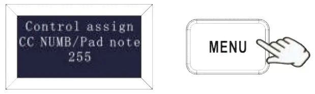
Control assignment
In control assignment mode the 8 assignable knobs/sliders and 8 assignable pads can be programmed to any MIDI controller messages that are used for controlling the MIDI-adjustable parameters in your software or on your external MIDI gear.
To select a different physical controller for programming, the method is: Press the MENU button repeatedly until the OLED displays “Control assign CC NUMB/Pad note”, then move the physical controller you wish to program. Input the desired controller value with value dial and confirm the value with “Enter” button. Holding the “Enter” button for 2 seconds to exit the edit mode.The OLED displays the following for control assignment: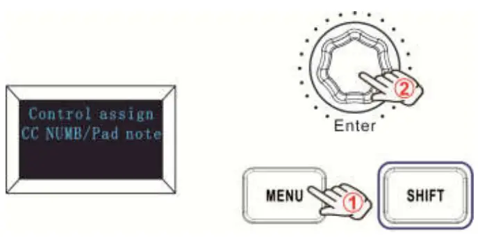
Assignable Knobs
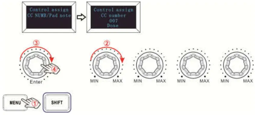
There’re 4 knobs that can be assigned as controller No. independently. Press the MENU button repeatedly until the OLED dispays “CC NUMB/Pad note”, then rotate the knobs you wish to program. Input the desired controller value with value dial and confirm the value with “Enter” button. For example, you may want to set the Knob1 to control the channel volume. This is done by assigning controller 7 to the Knob1 (first on the left). The operation steps is shown as below and the OLED displays the following:
- Press the MENU button repeatedly until the OLED dispays “Control assign CC NUMB/Pad note”.
- Rotate R1 knob (first on the left).
- Rotate the value dial until the OLED displays “007”. The numbers are the controllers.
- Press the “Enter” button to confirm and the OLED will display “Done”. Holding the “Enter” button for 2 seconds to exit the edit mode and return to parameter display mode. Then if you rotate the knobs, move the sliders or trigger the pads the OLED will display the current parameters of these controllers.

Assignable Sliders
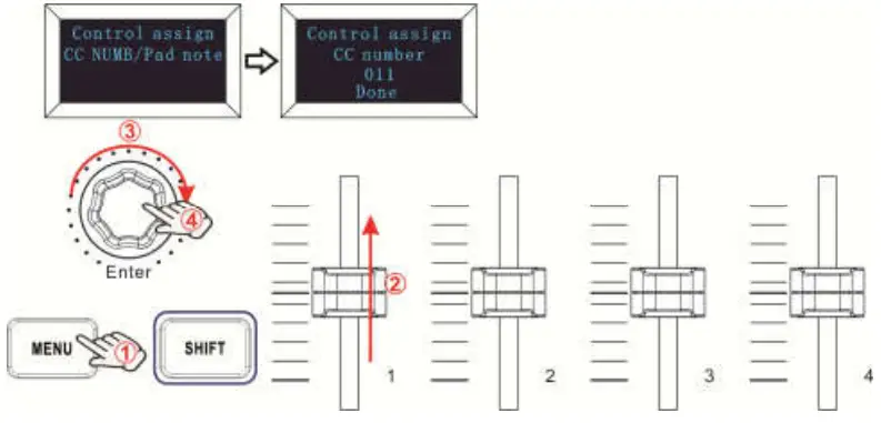
There’re 4 sliders that can be assigned as controller No. independently. Press the MENU button repeatedly until the OLED dispays “CC NUMB/Pad note”, then move the sliders you wish to program. Input the desired controller value with value dial and confirm the value with “Enter” button. For example, you may want to set the Slider F1 to control the expression control. This is done by assigning controller 11 to the F1 (first on the left). The operation steps is shown as below and the OLED displays the following:
- Press the MENU button repeatedly until the OLED dispays “Control assign CC NUMB/Pad note”.
- Move F1 slider (first on the left).
- Rotate the value dial until the OLED displays “011”. The numbers are the controllers.
- Press the “Enter” button to confirm and the OLED will display “Done”. Holding the “Enter” button for 2 seconds to exit the edit mode and return to parameter display mode.Then if you rotate the knobs, move the sliders or trigger the pads the OLED will display the current parameters of these controllers.

Assignable Pads
Pad Note Setting
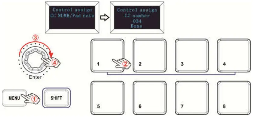
There’re 8 pads that can be assigned to transmit MIDI note messages (drums, stabs, bass notes, whatever). Press the MENU button repeatedly until the OLED dispays “CC NUMB/Pad note”, then trigger the pads you wish to program. Input the desired MIDI note messages with value dial and confirm the value with “Enter” button. Holding the “Enter” button for 2 seconds to exit the edit mode. For example, you may want to set the Pad1 to transmit note message 34. This is done by assigning controller 34 to the Pad1. The operation steps is shown as below and the OLED displays the following:
- Press the MENU button repeatedly until the OLED dispays “Control assign CC NUMB/Pad note”.
- Trigger the Pad1.
- Rotate the value dial until the OLED displays “34”. The numbers are the controllers.
- Press the “Enter” button to confirm and the OLED will display “Done”. Holding the “Enter” button for 2 seconds to exit the edit mode and return to parameter display mode.Then if you rotate the knobs, move the sliders or trigger the pads the OLED will display the current parameters of these controllers.

Advanced Settings
Keyboard Velocity Curve
Every time you press a key, a MIDI note message is sent with a velocity value between 0 and the maximum; this value specifies how hard you pressed the key. Since different people have different playing styles, your PANDAMINI II offers 3 different velocity curves and 1 one constant velocity as shown below. The default is the first one. You should experiment with the different velocity curves to seek the curve that best suits your playing style.
Keyboard Velocity Curves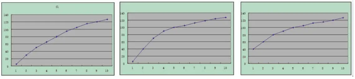
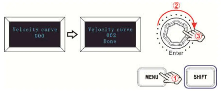
To change the keyboard velocity curve:
Press the MENU button repeatedly until the OLED dispays “Velocity curve” to start the function of selecting keyboard velocity curve. When this function is valid, the OLED displays the “Velocity curve” and the Number of current velocity curve. It can be adjusted by value dial and confirmed by Enter button. The initial value is 1, adjusting scale is 1~4. The operation steps is shown as below and the OLED displays the following:
- Press the MENU button repeatedly until the OLED dispays “Velocity curve”.
- Rotate the value dial to adjust the keyboard velocity curve, the OLED will display the current selected velocity curve.
- Press the “Enter” button to confirm and the OLED will display “Done”. Holding the “Enter” button for 2 seconds to exit the edit mode and return to parameter display mode.Then if you rotate the knobs, move the sliders or trigger the pads the OLED will display the current parameters of these controllers.

Pad Velocity
The Pad Curve setting is used to set the response curve of all 8 pads. It is not possible to set the response curve of the pads independently.
Your PANDAMINI II offers 3 different pad velocity curves and 1 one constant velocity as shown below. The 3rd one is the constant velocity with the value 127.
Pad Velocity Curves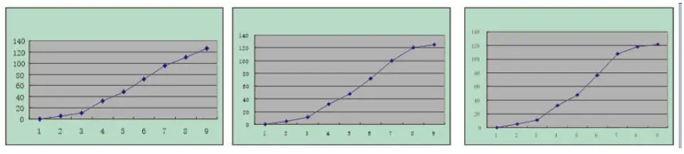
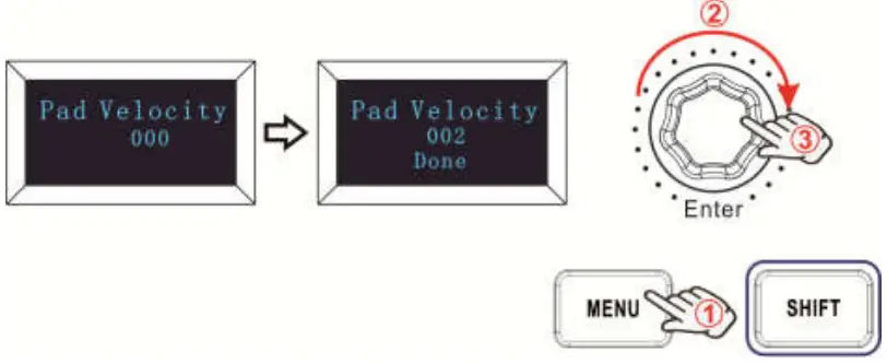
To change the pad velocity curve:
Press the MENU button repeatedly until the OLED dispays “Pad curve” to start the function of selecting pad velocity curve. When this function is valid, the OLED displays the “Pad velocity” and the Number of current pad velocity curve. It can be adjusted by value dial and confirmed by Enter button. The initial value is 1, adjusting scale is 1~4. The operation steps is shown as below and the OLED displays the following:
- Press the MENU button repeatedly until the OLED dispays “Pad Velocity”.
- Rotate the value dial to adjust the pad velocity curve, the OLED will display the current selected velocity curve.
- Press the “Enter” button to confirm and the OLED will display “Done”. Holding the “Enter” button for 2 seconds to exit the edit mode and return to parameter display mode.Then if you rotate the knobs, move the sliders or trigger the pads the OLED will display the current parameters of these controllers.

OCTAVE+/ OCTAVE-
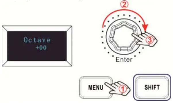
Press the MENU button repeatedly until the OLED dispays “Octave” to start the function of Octave. This function allows the keyboard to change the Pitch up/down by octave. When this function is valid, the OLED displays the “Octave” and the value of current transposition. It can be adjusted by value dial. The initial value is 0, adjusting scale is -4~4. The operation steps is shown as below and the OLED displays the following:
- Press the MENU button repeatedly until the OLED dispays “Octave”.
- Rotate the value dial to adjust the keyboard octave, the OLED will display the current octave. Holding the “Enter” button for 2 seconds to exit the edit mode and return to parameter display mode.Then if you rotate the knobs, move the sliders or trigger the pads the OLED will display the current parameters of these controllers.

Transpose
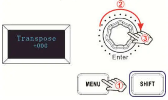
Press the MENU button repeatedly until the OLED dispays “Transpose” to start the function of Transpose. This function allows the keyboard to change the Pitch up/down by semi-tone. When this function is valid, the OLED displays the “Transpose” and the value of current transpose. It can be adjusted by value dial. The initial value is 0, adjusting scale is -12~12. The operation steps is shown as below and the OLED displays the following:
- Press the MENU button repeatedly until the OLED dispays “Transpose”.
- Rotate the value dial to adjust the keyboard transpose, the OLED will display the current transpose. Holding the “Enter” button for 2 seconds to exit the edit mode and return to parameter display mode.Then if you rotate the knobs, move the sliders or trigger the pads the OLED will display the current parameters of these controllers.

Program change
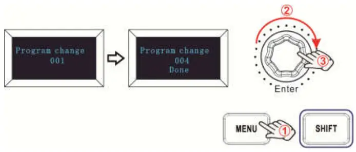
Press the MENU button repeatedly until the OLED dispays “Program change” to start the function of Program change. Program change is for adjusting the voice of current channel. When this function is valid, the OLED displays the “Program change” and the current voice number. It can be adjusted by value dial and confirmed by Enter button. The initial value is 1, adjusting scale is 1~128. The operation steps is shown as below and the OLED displays the following:
- Press the MENU button repeatedly until the OLED dispays “Program change”.
- Rotate the value dial to adjust the keyboard program, the OLED will display the current keyboard program.
- Press the “Enter” button to confirm and the OLED will display “Done”. Holding the “Enter” button for 2 seconds to exit the edit mode and return to parameter display mode.Then if you rotate the knobs, move the sliders or trigger the pads the OLED will display the current parameters of these controllers.

MIDI channel
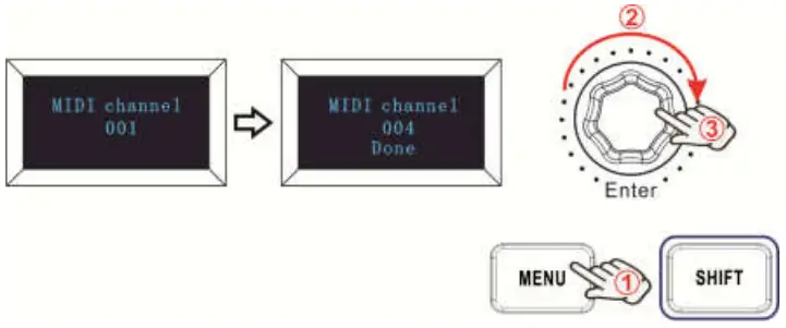
Press the MENU button repeatedly until the OLED dispays “MIDI channel” to start the function of Channel selection. Channel selection is for adjusting the Current MIDI channel. When this function is valid, the OLED displays the “MIDI channel” and the current channel number. It can be adjusted by value dial and confirmed by Enter button. The initial value is 1, adjusting scale is 1~16. The operation steps is shown as below and the OLED displays the following:
- Press the MENU button repeatedly until the OLED dispays “MIDI channel”.
- Rotate the value dial to adjust the keyboard MIDI Channel, the OLED will display the current MIDI channel.
- Press the “Enter” button to confirm and the OLED will display “Done”. Holding the “Enter” button for 2 seconds to exit the edit mode and return to parameter display mode.Then if you rotate the knobs, move the sliders or trigger the pads the OLED will display the current parameters of these controllers.

Select the Backlit RGB Color of 8 Pads
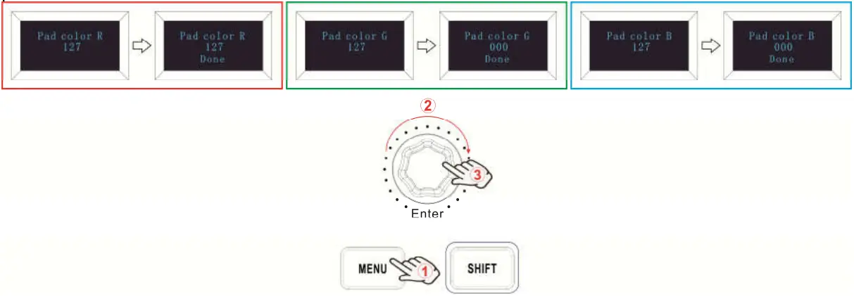
Press the MENU button repeatedly until the OLED dispays “Pad color R/G/B” to start the function of selecting the Backlit RGB Color of 8 Pads. When this function is valid, the OLED displays the “Pad color R/G/B” and the current RGB color number. R is for red, G is for green and B is for blue. It can be adjusted by value dial and confirmed by Enter button. The initial value is 127, adjusting scale is 0~255. For example, you may want to set the Pad1 with RED color for the RGB backlight. This is done by setting the Pad color R to 127, Pad color G to 0 and Pad color B to 0 to the Pad1. The operation steps is shown as below and the OLED displays the following:
- Trigger the Pad1.
- Press the MENU button repeatedly until the OLED dispays “Pad color R”.
- Rotate the value dial until the OLED displays 127.
- Press the “Enter” button to confirm and the OLED will display “Done”.
- Press the MENU button repeatedly until the OLED dispays “Pad color G”.
- Rotate the value dial until the OLED displays 0.
- Press the “Enter” button to confirm and the OLED will display “Done”.
- Press the MENU button repeatedly until the OLED dispays “Pad color B”.
- Rotate the value dial until the OLED displays 0.
- Press the “Enter” button to confirm and the OLED will display “Done”. Holding the “Enter” button for 2 seconds to exit the edit mode and return to parameter display mode.Then if you rotate the knobs, move the sliders or trigger the pads the OLED will display the current parameters of these controllers.

Reference RGB No. for some colors: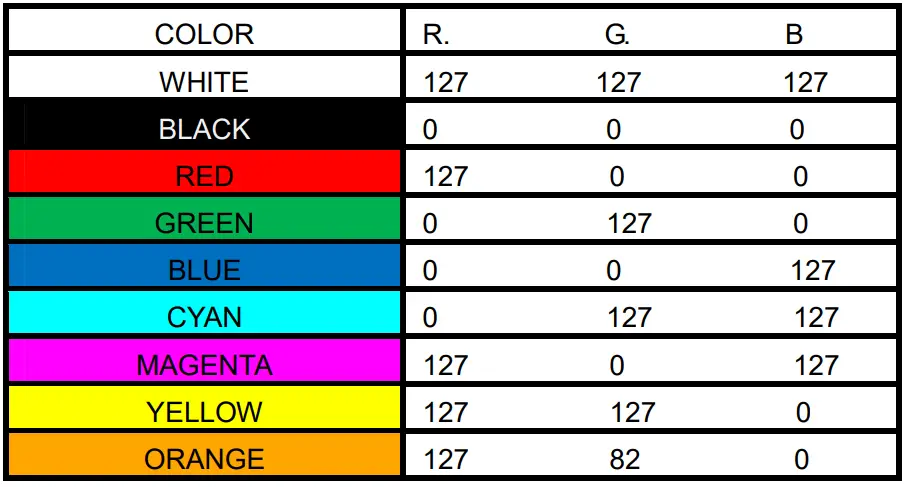
Other controls
Store all parameters
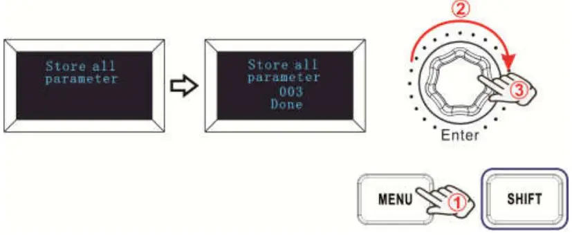
Press the MENU button repeatedly until the OLED displays “Store all parameters” to start the function of storing parameters. It stores 3 groups setup value. When this function is valid, the OLED displays the “Store all parameter” and the current storage group number. It can be adjusted by value dial and confirmed by Enter button. The initial value is 1, adjusting scale is 1~3. The operation steps is shown as below and the OLED displays the following:
- Press the MENU button repeatedly until the OLED dispays “Store all parameter”.
- Rotate the value dial to adjust the memory area and the OLED will display the current memory area.
- Press the “Enter” button to confirm and the OLED will display “Done”. Holding the “Enter” button for 2 seconds to exit the edit mode and return to parameter display mode.Then if you rotate the knobs, move the sliders or trigger the pads the OLED will display the current parameters of these controllers.

Recall all parameters
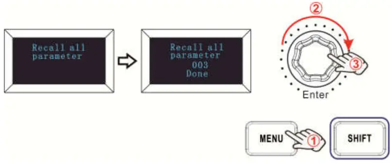
Press the MENU button repeatedly until the OLED dispays “Recall all parameter” to start the function of recalling all parameters. When this function is valid, the OLED displays the “Recall all parameter” and the current strorage group number. It can be adjusted by value dial and confirmed by Enter button. The initial value is 1, adjusting scale is 1~3. The operation steps is shown as below and the OLED displays the following:
- Press the MENU button repeatedly until the OLED dispays “Recall all parameter”.
- Rotate the value dial to select the memory area and the OLED will display the current memory area.
- Press the “Enter” button to confirm and the OLED will display “Done”. Holding the “Enter” button for 2 seconds to exit the edit mode and return to parameter display mode.Then if you rotate the knobs, move the sliders or trigger the pads the OLED will display the current parameters of these controllers.

RESET
Press the MENU button repeatedly until the OLED dispays “Reset all” to reset the system restoring to factory setting, sending system initial setting info at the same time. When this function is valid, the OLED displays the “Reset all”. It can be confirmed by Enter button. The OLED displays the following: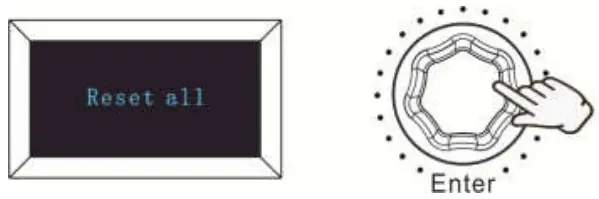
Sequencer remote control buttons
There are 2 buttons used for Playback and Record control:[>>], [O]. It is common to set the 2 buttons as Sequencer remote control buttons, it needs to be working with sequencer software.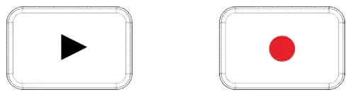
Using The PANDAMINI II With Your DAW
Using your PANDAMINI II with Ableton Live
With Ableton Live installed, get your PANDAMINI II connected to Mac or PC ‘s USB port with USB cable and it will be automatically detected and enter Session mode. If you press the Shift button on your PANDAMINI II the pads will be lighting as shown in the picture below. The first 2 pads of the top row are used to select pad behavior and the last pad is for selecting knob behaviour.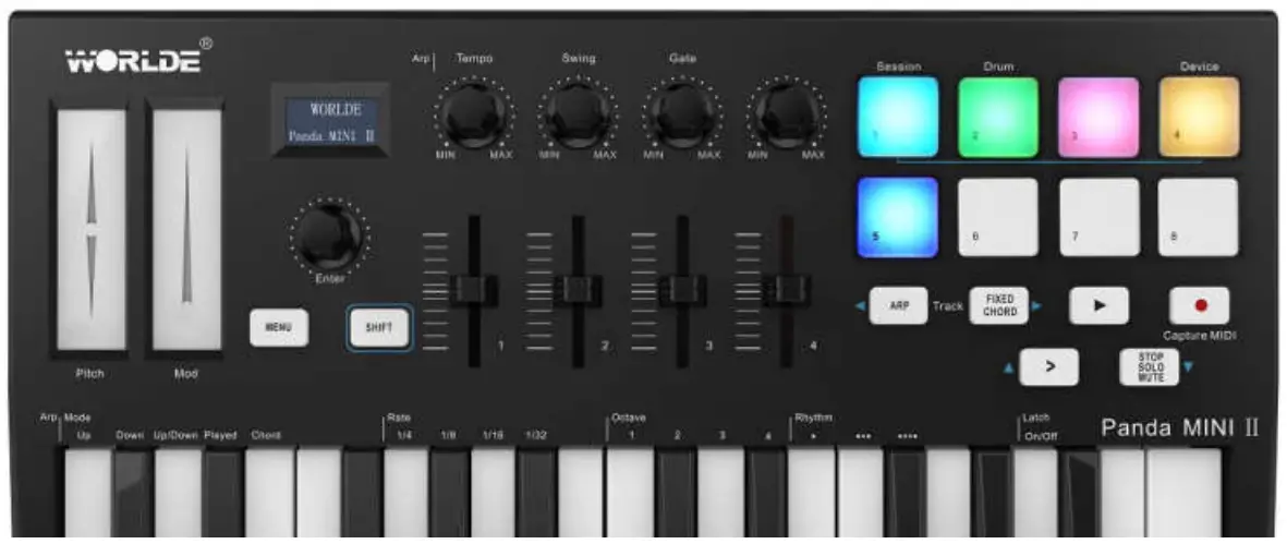
If your PANDAMINI II is not automatically detected in Ableton Live, you’ll need to configure Live’s Control Surface Preferences. This could be done in the ‘Link/MIDI’ Preferences menu in Ableton Live:
‘Link/MIDI’ Preferences:
Windows:Options>Preferences>Link/MIDI
Mac:Live>Preferences>Link/MIDI
You need to make settings in the Link/MIDI tab as steps shown below. First, select the PANDAMINI II(Launchkey Mini [MK3]) from the Control Surface menu. Second, select WORLDE or WORLDE2(Windows) for Input and Output settings. Finally, match the Track, Sync and Remote settings.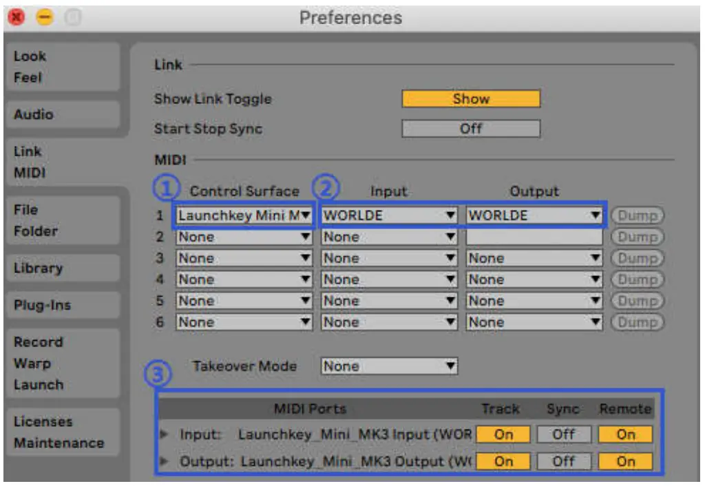
Session Mode
Hold the Shift button and press the Session pad(the top left pad) to enter session mode on your PANDAMINI II.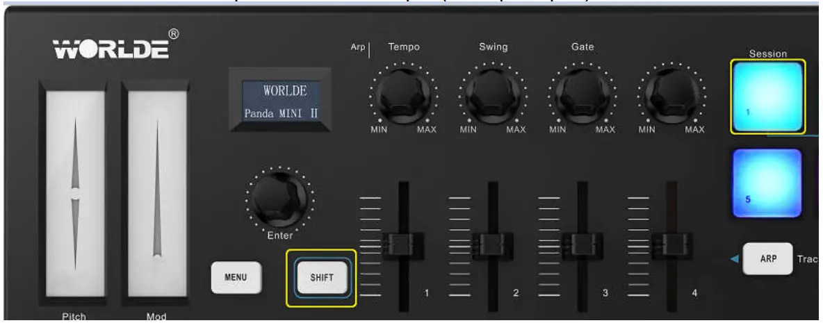
Session mode is used to control Ableton Live’s Session view. Session View is a grid that consists of clips, tracks and scenes.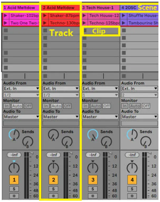
PANDAMINI II’s Session mode provides an 4×2 view of the clips in your Session View.
Example of PANDAMINI II’s pads in Session mode: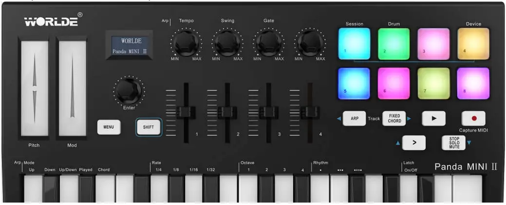
Clips are typically loops that contain MIDI notes or audio.
Tracks represent virtual instruments or audio tracks. MIDI clips placed on instrument tracks will play back on the instrument that is assigned to that track.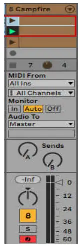
Scenes are rows of clips. Launching a scene will launch all clips in that row. This means that you can arrange clips into horizontal groups (across tracks) to form a song structure, launching scene after scene to progress through a song.![]()
In Session mode, the pads represent the grid of clips found inside the coloured rectangle in Ableton Live’s Session View. The image below shows such a rectangle (red) extending from the left-most track to the Master track: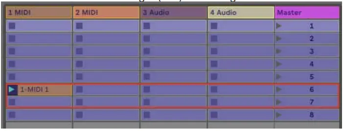
Any changes you make to clip position or colour within Ableton Live will be represented in the Session mode of PANDAMINI II. Unlit (dark) pads indicate empty clip slots.
You can navigate around Session View by holding Shift and pressing the 4 buttons with arrows as their secondary functions: >, Stop Solo Mute, Arp, and Fixed Chord.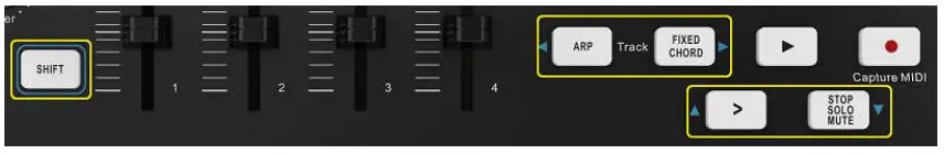
More specifically, you can move the currently selected grid of clips (inside Ableton Live’s coloured rectangle) up or down by holding Shift and pressing the following buttons: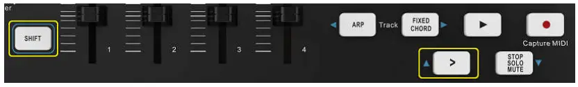
Shift + Scene Launch (>) – This moves the grid of clips up one row.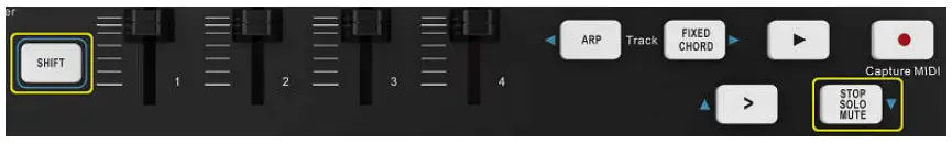
Shift + Stop, Solo, Mute – This moves the grid of clips down one row.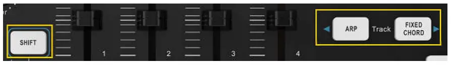
Holding Shift and pressing Arp (left) or Fixed Chord (right) will select the adjacent left or right track. This will automatically arm the track so it is ready to receive MIDI. Release Arp or Fixed Chord button first before SHIFT button released.
Launching Clips
Pressing pads will launch clips in the corresponding location in your Session View. Pads will pulse white to indicate that a clip is playing.
Pressing the pad again will relaunch the clip, and pressing an empty pad will stop playback on that track.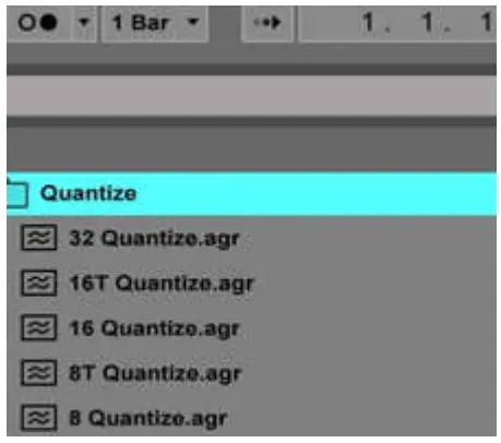
How fast clips stop or relaunch is set by Ableton Live’s Global Quantisation chooser, located at the top of the Live screen. By default, this is set to 1 bar, but can go as fast as 1/32 notes, or as slow as 8 bars. It can also be set to ‘None’ so clips react immediately.
Launching Scenes
Pressing the Scene Launch button (>) launches scenes in Ableton Live. This means that all of the clips in a row can start together.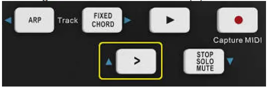
Stop, Solo, Mute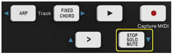
While in Session mode, it is possible to switch the functionality of the bottom 4 pads so that they no longer launch clips. This is done with the Stop, Solo, Mute button.
The Stop, Solo, Mute button toggles between four different states which affect tracks in the following ways:
Stop (Purple) – In this state, pressing pads will stop any clip on the corresponding track. The purple pads will be in blue if tracks are not playing.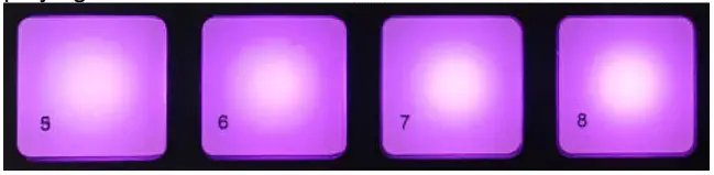
Solo (Yellow green) – In this state, pressing the pads will solo the corresponding tracks, meaning only tracks with Solo on will be heard.
The pads will be in yellow green if tracks are not soloed (ie they are silent) and if soloed they will be in purple.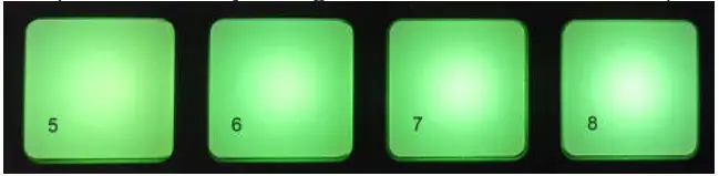
Mute (Light pink) –In this state, pressing pads will mute the corresponding tracks.
The pads will be in yellow green for muted tracks, leaving pads for unmuted tracks at their original light pink colour.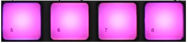
Clips (White) – the fourth press (after toggling through Stop, Solo and Mute) changes the function of bottom pads back to the default Session mode, where the bottom row of pads will represent clips again . The clips that are playing will be in white color and flickering.
Record / Capture MIDI
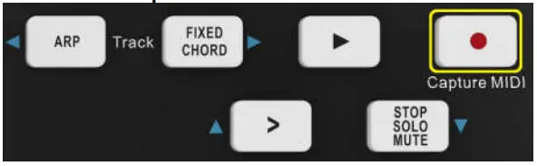
Pressing this button triggers Session Record. This will allow you to record what you’re playing to new clips as well as overdub existing ones.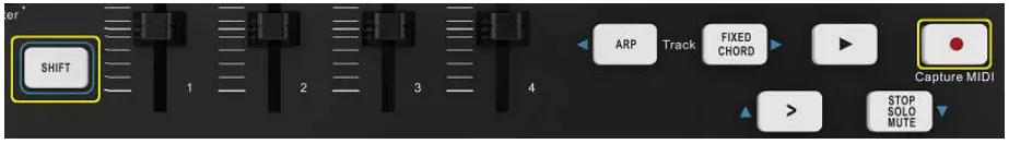
Holding Shift and pressing Record triggers the Capture MIDI function. This allows you to retrospectively capture any recently played MIDI notes in the record-armed track. This means that if you are not recording, but you play something that sounds great, you can use Capture MIDI to send it straight into a clip.
Playing and Recording Drums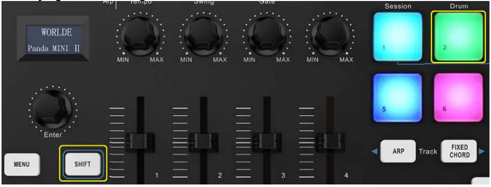
Drum mode transforms the PANDAMINI II’s pads into velocity-sensitive drum pads.
Hold Shift and press the Drum pad (2nd from the top left) to enter this mode.
If a Drum Rack (an Ableton MIDI instrument) is loaded onto the selected Live track, and the PANDAMINI II is in Drum mode, the pads light up the colour of the track. These pads will play whatever Drum Rack pads are visible on your computer screen.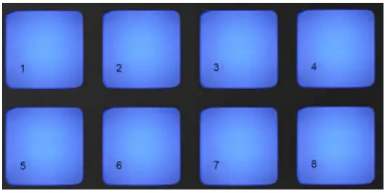
Hold Shift and press either the > or Stop, Solo, Mute buttons to scroll up/down a Drum Rack’s bank of 128 pads.
When using Ableton’s Drum Racks, Drum mode will – apart from triggering sounds – select the associated Drum Rack pad within a Drum Rack. This means that on release, the last played Drum Rack pad becomes grey and Ableton Live shows the selected Drum Rack pad on the screen.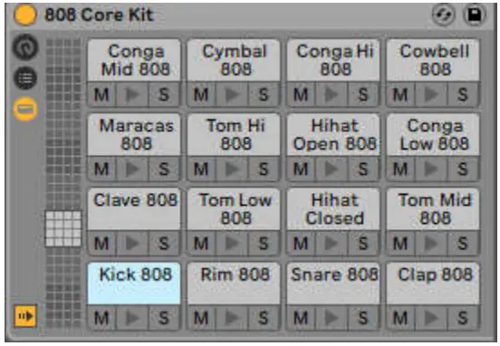
Using Ableton Live Devices
Device mode allows you to control the selected ‘device’ (Ableton or 3rd-party Instruments and Effects) on a Live track. Hold the Shift button and press the Device pad (4th from top left) to use this mode.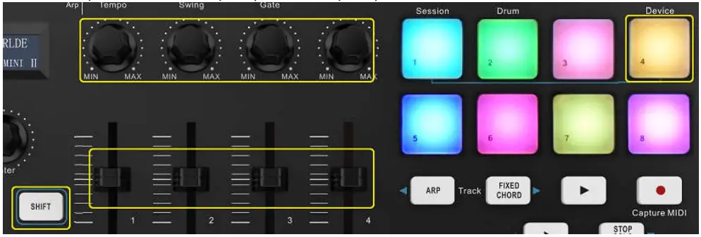
In this mode, knobs and sliders control the first 8 parameters of the selected device. This is especially useful for controlling Live’s 8 ‘macro’ knobs, available on Instrument and Effect Racks.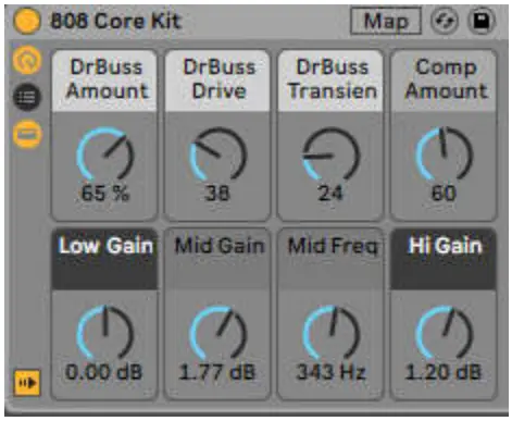
The above picture shows an Impulse preset called ‘Percussion 1’. Here, the PANDAMINI II knobs and sliders control sample volumes, sample start and ‘stretch’, as well as delay and reverb amounts.
Arp
Pressing the Arp button on PANDAMINI II enables the Arpeggiator. After engaging Arp the PANDAMINI II takes your chords and creates an arpeggio – ie it plays each note of the chord one after another. The Arpeggiator will run as long as keys are held, at the rhythmic value specified by the Arp Rate.
PANDAMINI II’s Arp is a great way to come up with interesting melodies and progressions with ease.
Arpeggiator Rotary Knobs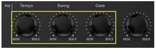
When you hold the Arp button the rotary knobs can transform your arpeggios.
Tempo – This knob speeds up or slows down your arpeggio relative to the Arp Rate.
Swing – This knob sets the amount that every other note is delayed, resulting in a swung rhythm. To change the Arpeggiator’s Swing, press and hold the Arp button, and then turn the knob labelled Swing. By default (centre position), swing will be set to 50% (meaning no swing), with extremes of 80% (very swung) and 20% (negative swing). Negative swing means every other note is rushed, instead of delayed.
Gate – Adjusting this knob will create longer or shorter MIDI notes, resulting in either a more ‘staccato’ arpeggio, or a more fluid, ‘legato’ one. This knob goes from 1% to 200% of the space between notes. For notes that have swing applied, both notes retain the same gate length.
Arp Modes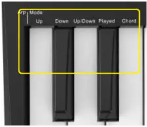
After turning on Arp you’ll be in 1 of 5 Arpeggiator Modes, each resulting in arpeggios of different note orders. To change the Arp Mode,
press and hold the Arp button, and then press the key corresponding to your desired mode.
Up – Here notes are played in ascending order (ie rising in pitch). If notes are added, the number of notes in the sequence will grow but remain in ascending order. For example, you may start by holding down a first note – E3 – then quickly add two more notes – C3 and G3.
The resulting arpeggio will be C3, E3 and G3.
Down – This Mode is similar to Up Mode, but notes play in descending order (eg G3, E3, C3).
Up/Down – This arpeggio Mode starts by playing notes in ascending order. Then, after reaching the highest note, the notes descend towards the lowest note, which plays once before the arpeggio rises again and stop before reaching the lowest note. This means that when the pattern repeats, the lowest note only plays once.
Played – Here notes are kept repeated in whatever order they were played.
Chord – All notes are played back on every rhythmic step (see Arp Rate). This makes playing fast chords very easy.
Arp Rates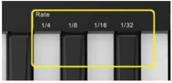
These options specify the speed of the arpeggiated notes. Since each note is played immediately after the end of the previous one, a shorter rate (eg 1/32) will play an arpeggio faster than longer one (eg 1/4).
Rate options are common musical note values: quarter (¼), eighth (1/8), sixteenth (1/16) and thirty-second (1/32) notes. To change the Arp Rate, press and hold the Arp button, and then press the key below 1/4, 1/8, 1/16, or 1/32.
Arp Octaves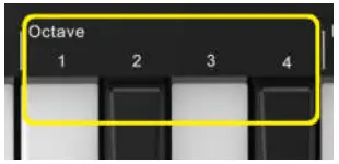
These 4 keys specify across how many octaves your arpeggio will repeat. To change, press and hold the Arp button, and then press the key below 1, 2, 3 or 4. Choosing an octave higher than 1 will repeat the arpeggio at higher octaves. For example, an arpeggio that was C3, E3, and G3 at 1 octave will become C3, E3, G3, C4, E4, and G4 when set to 2 octaves.
Arp Rhythms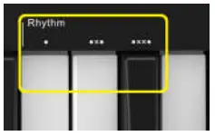
Arp Rhythms add musical rests (silent steps) to your arpeggio’s pattern, allowing for greater variations in your arpeggios.
Dots – These three options are rhythmic patterns.
O – The normal Arpeggiator setting, this places a note on every division of the selected Arp rate.
OXO (note – rest – note) – This rhythm adds a rest between every pair of notes.
OXXO (note – rest – rest – note) – This pattern adds two rests between every pair of notes.
Latch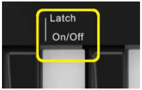
Latch lets you use the Arpeggiator without holding down keys. Any notes you press and release concurrently will form a new arpeggio pattern which the arpeggiator ‘latches’ onto. The arpeggiator then continues to play as if you never released the keys. When you press a new key, the previous arpeggio erases and a new one forms.
To turn on Latch, press and hold the Arp button, and then press the key below ‘Latch’.
Fixed Chord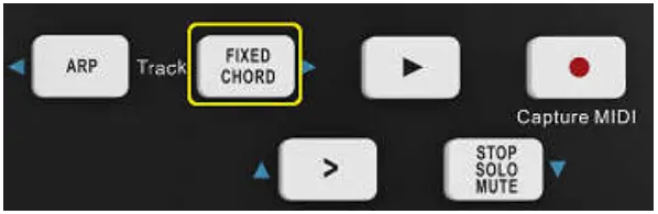
Fixed Chord lets you play a chord shape and then transpose it by pressing other keys.
Press and hold the Fixed Chord button to set a chord. Then, while still holding the button, press and release the keys that you wish to be part of your chord. The chord is now stored.
Keep in mind that the first note that you input into the chord is considered the ‘root note’ of the chord, even if you then add notes lower than the first one, like in the example below.
These steps illustrate how to use Fixed Chord:
Press and hold the Fixed Chord button.
Press and release C, then E, and finally G (a C Major chord). PANDAMINI II stores this as the ‘fixed chord’.
Release the Fixed Chord button.
Major chords will now sound on whatever key you press. For example, you can now press F to hear an F Major chord (shown below), or
Ab to hear an Ab Major chord, etc. Whenever you enter the Fixed Chord settings, the stored chord is erased and a new chord must be entered for Fixed Chord to work again.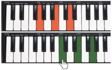
PANDAMINI II Working with other Sequencer
A MIDI sequencer will allow you to record, play back, store and edit MIDI data. Although hardware sequencers exist, we will focus on the more commonly used software sequencers in this manual. Examples of popular DAW are CubaseTM, LogicTM, Ableton Live TM and so on, although there are many different sequencing applications available for your computer. In order to use your PANDAMINI II with your sequencer, you need to set up the sequencer software so that your PANDAMINI II can be recognized as your DAW’s MIDI input device. You need to choose a MIDI output device that is capable of making sound when MIDI data is sent to it. This may be a soundcard on your computer, a VST instrument or a sound module connected to a MIDI port which is in turn connected to your computer. Please consult your sequencer’s user manual for more information on how this is done. In this manual, section 3.2.2 “Using The PANDAMINI II With Your software” details how your PANDAMINI II will appear in the device listing of your sequencer.
With your PANDAMINI II set up to communicate with the sequencer, data will go into the sequencer and will be routed to a virtual synthesizer within the sequencer software or sent to an external sound module via a MIDI output port. The virtual synthesizer or external sound module will turn the MIDI data into audible sounds. You can then record the incoming MIDI data and edit your performance using your sequencer. We will have some more detailed MIDI mapping operations for different DAWs provided separately.
Appendices
Appendix A-ASSIGNABLE CONTROLLER PARAMETER LIST
| CONTROLLER NO. | DEFINITION | INITIAL VALUE | VALUE RANGE |
| 0 | Bank Select MSB | 0 | 0-127 |
| 1 | Modulation MSB | 0 | 0-127 |
| 2 | Breath MSB | 127 | 0-127 |
| 3 | Controller | 0 | 0-127 |
| 4 | Foot Controller MSB | 127 | 0-127 |
| 5 | Portamento time MSB | 0 | 0-127 |
| 6 | Data Entry MSB | 2 | 0-127 |
| 7 | Channel Volume MSB | 100 | 0-127 |
| 8 | Balance MSB | 64 | 0-127 |
| 9 | Controller | 0 | 0-127 |
| 10 | Panpot MSB | 64 | 0-127 |
| 11 | Expression MSB | 127 | 0-127 |
| 12 | Effect Control 1 MSB | 0 | 0-127 |
| 13 | Effect Control 2 MSB | 0 | 0-127 |
| 14-31 | Controller | 0 | 0-127 |
| 32 | Bank Select LSB | 0 | 0-127 |
| 33 | Modulation LSB | 0 | 0-127 |
| 34 | Breath LSB | 127 | 0-127 |
| 35 | Controller | 0 | 0-127 |
| 36 | Foot Controller LSB | 127 | 0-127 |
| 37 | Portamento time LSB | 0 | 0-127 |
| 38 | Data Entry LSB | 0 | 0-127 |
| 39 | Channel Volume LSB | 127 | 0-127 |
| 40 | Balance LSB | 64 | 0-127 |
| 41 | Controller | 0 | 0-127 |
| 42 | Panpot LSB | 64 | 0-127 |
| 43 | Expression LSB | 127 | 0-127 |
| 44-63 | Controller | 0 | 0-127 |
| 64 | Sustain | 0 | 0-127 |
| 65 | Portamento | 0 | 0-127 |
| 66 | Sostenuto | 0 | 0-127 |
| 67 | Soft Pedal | 0 | 0-127 |
| 68 | Legato FootSwitch | 0 | 0-127 |
| 69 | Hold 2 | 0 | 0-127 |
| 70 | Sound Controller | 64 | 0-127 |
| 71 | Resonance | 64 | 0-127 |
| 72 | Release Time | 64 | 0-127 |
| 73 | Attack Time | 64 | 0-127 |
| 74 | Cutoff | 64 | 0-127 |
| 75 | Decay Time | 0 | 0-127 |
| 76 | Vibrato Depth | 64 | 0-127 |
| 77 | Vibrato Depth | 64 | 0-127 |
| 78 | Vibrato Depth | 64 | 0-127 |
| 79 | Sound Controller | 64 | 0-127 |
| 80-83 | Controller | 0 | 0-127 |
| 84 | Portamento Control | 0 | 0-127 |
| 85-90 | Controller | 0 | 0-127 |
| 91 | Reverb | 40 | 0-127 |
| 92 | Effects | 0 | 0-127 |
| 93 | Chorus | 0 | 0-127 |
| 94 | Effects | 0 | 0-127 |
| 95 | Effects | 0 | 0-127 |
| 96 | RPN Increment | 0 | 0-127 |
| 97 | RPN Decrement | 0 | 0-127 |
| 98 | NRPN LSB | 0 | 0-127 |
| 99 | NRPN MSB | 0 | 0-127 |
| 100 | RPN LSB | 0 | 0-127 |
| 101 | RPN MSB | 0 | 0-127 |
| 102-119 | Controller | 0 | 0-127 |
| 120 | All Sound Off | 0 | 0-127 |
| 121 | Reset All Controllers | 0 | 0-127 |
| 122 | Local Control | 0 | 0-127 |
| 123 | All Notes Off | 0 | 0-127 |
| 124 | OMNI Off | 0 | 0-127 |
| 125 | OMNI On | 0 | 0-127 |
| 126 | Mono | 0 | 0-127 |
| 127 | Poly | 0 | 0-127 |
| 128 | Pitch Bend Sensitivity(RPN) | 2 | 0-127 |
| 129 | Channel Fine Tuning(RPN) | 64 | 0-127 |
| 130 | Channel Coarse Tuning(RPN) | 64 | 0-127 |
| 131 | Modulation Depth Range(RPN) | 64 | 0-127 |
| 132 | Vibrato Rate(NRPN) | 64 | 0-127 |
| 133 | Vibrato Depth(NRPN) | 64 | 0-127 |
| 134 | Vibrato Delay(NRPN) | 64 | 0-127 |
| 135 | Filter Cutoff Frequency(NRPN) | 64 | 0-127 |
| 136 | Filter Resonance(NRPN) | 64 | 0-127 |
| 137 | EQ Low Gain(NRPN) | 64 | 0-127 |
| 138 | EQ High Gain(NRPN) | 64 | 0-127 |
| 139 | EQ Low Frequency(NRPN) | 64 | 0-127 |
| 140 | EQ High Frequency(NRPN) | 64 | 0-127 |
| 141 | EG Attack Time(NRPN) | 64 | 0-127 |
| 142 | EG Decay Time(NRPN) | 64 | 0-127 |
| 143 | EG Release Time(NRPN) | 64 | 0-127 |
| 144 | Polyphonic key pressure | 100 | 0-127 |
| 145 | After touch | 100 | 0-127 |
| 146 | Pitch Bend | 64 | 0-127 |
| 147 | Master Volume | 100 | 0-127 |
| 148 | Start(MTC) | – | – |
| 149 | Continue(MTC) | – | – |
| 150 | Stop(MTC) | – | – |
| 151 | Reset(MTC) | – | – |
| 152 | Program | 0 | 0-127 |
| 153 | Global Channel | 0 | 0-15 |
| 154 | Octave | 0 | -3~3 |
| 155 | Transpose | 0 | -12~12 |
| 156 | Tempo | 100 | 20-250 |
| 157 | Keyboard Curve | 0 | 0-4 |
| 158 | Pedal A Curve | 64 | 1-127 |
Appendix B- Toxic or Hazardous Substances and Elements
| Part Number, | Toxic or Hazardous Substances and Elements | |||||
| Name and Description | Pb | Hg | Cd | Cr(VI)) | (PBB) | (PBDE) |
| PCB | ○ | ○ | ○ | ○ | ○ | ○ |
| PCBA Welding Spot | ○ | ○ | ○ | ○ | ○ | ○ |
| Components | ○ | ○ | ○ | ○ | ○ | ○ |
| Metal Parts | ○ | ○ | ○ | ○ | ○ | ○ |
| Plastic and Polymeric parts | ○ | ○ | ○ | ○ | ○ | ○ |
| Paper Accessory | ○ | ○ | ○ | ○ | ○ | ○ |
| Power Cord | ○ | ○ | ○ | ○ | ○ | ○ |
| ○ :Indicates that this toxic or hazardous substance contained in all the homogeneous materials for this part, according to EIP-A, EIP-B, EIP-C is below the limit requirement in SJ/T 11364. ×:Indicates that this toxic or hazardous substance contained in all the homogeneous materials for this part, according to EIP-A, EIP-B, EIP-C is above the limit requirement in SJ/T 11364. (Enterprises may further provide in this box technical explanation for marking”X”based on their actual conditions.) | ||||||
Appendix C-Note Value and The Corresponding Numerical Number
| Note | NO. | Note | NO. | Note | NO. | Note | NO. | Note | NO. | Note | NO. | Note | NO. | Note | NO. |
| C-1 | 0 | F0 | 17 | Bb 1 | 34 | Eb 3 | 51 | G#4 | 68 | C#6 | 85 | F#7 | 102 | B8 | 119 |
| C#-1 | 1 | F#0 | 18 | B1 | 35 | E3 | 52 | A4 | 69 | D6 | 86 | G7 | 103 | C9 | 120 |
| D-1 | 2 | G0 | 19 | C2 | 36 | F3 | 53 | Bb 4 | 70 | Eb 6 | 87 | G#7 | 104 | C#9 | 121 |
| Eb-1 | 3 | G#0 | 20 | C#2 | 37 | F#3 | 54 | B4 | 71 | Eb 6 | 88 | A7 | 105 | D9 | 122 |
| E-1 | 4 | A0 | 21 | D2 | 38 | G3 | 55 | C5 | 72 | F6 | 89 | Bb 7 | 106 | Eb 9 | 123 |
| F-1 | 5 | Bb 0 | 22 | Eb 2 | 39 | G#3 | 56 | C#5 | 73 | F#6 | 90 | B7 | 107 | E9 | 124 |
| F#-1 | 6 | B0 | 23 | E2 | 40 | A3 | 57 | D5 | 74 | G6 | 91 | C8 | 108 | F9 | 125 |
| G-1 | 7 | C1 | 24 | F2 | 41 | Bb 3 | 58 | Eb 5 | 75 | G#6 | 92 | C#8 | 109 | F#9 | 126 |
| G#-1 | 8 | C#1 | 25 | F#2 | 42 | B3 | 59 | E5 | 76 | A6 | 93 | D8 | 110 | G9 | 127 |
| A-1 | 9 | D1 | 26 | G2 | 43 | C4 | 60 | F5 | 77 | Bb 6 | 94 | Eb 8 | 111 | ||
| Bb-1 | 10 | Eb 1 | 27 | G#2 | 44 | C#4 | 61 | F#5 | 78 | B6 | 95 | E8 | 112 | ||
| B-1 | 11 | E1 | 28 | A2 | 45 | D4 | 62 | G5 | 79 | C7 | 96 | F8 | 113 | ||
| C0 | 12 | F1 | 29 | Bb 2 | 46 | Eb 4 | 63 | G#5 | 80 | C#7 | 97 | F#8 | 114 | ||
| C#0 | 13 | F#1 | 30 | B2 | 47 | E4 | 64 | A5 | 81 | D7 | 98 | G8 | 115 | ||
| D0 | 14 | G1 | 31 | C3 | 48 | F4 | 65 | Bb 5 | 82 | Eb 7 | 99 | G#8 | 116 | ||
| Eb 0 | 15 | G#1 | 32 | C#3 | 49 | F#4 | 66 | B5 | 83 | E7 | 100 | A8 | 117 | ||
| E0 | 16 | A1 | 33 | D3 | 50 | G4 | 67 | C6 | 84 | F7 | 101 | Bb 8 | 118 |
Appendix D- General MIDI Instruments-Program Change Numbers
| Piano | Bass | Reed | Synth Effects |
| 0 Acoustic Grand Piano | 32 Acoustic Bass | 64 Soprano Sax | 96 SFX Rain |
| 1 Bright Acoustic Piano | 33 Fingered Bass | 65 Alto Sax | 97 SFX Soundtrack |
| 2 Electric grand Piano | 34 Electric Picked Bass | 66 Tenor Sax | 98 SFX Crystal |
| 3 Honky Tonk Piano | 35 Fretless Bass | 67 Baritone Sax | 99 SFX Atmosphere |
| 4 Electric Piano 1 | 36 Slap Bass 1 | 68 Oboe | 100 SFX Brightness |
| 5 Electric Piano 2 | 37 Slap Bass 2 | 69 English Horn | 101 SFX Goblins |
| 6 Harpsichord | 38 Syn Bass 1 | 70 Bassoon | 102 SFX Echoes |
| 7 Clavinet | 39 Syn Bass 2 | 71 Clarinet | 103 SFX Sci-Fi |
| Chromatic Percussion | Strings/Orchestra | Pipe | Ethnic |
| 8 Celesta | 40 Violin | 72 Piccolo | 104 Sitar |
| 9 Glockenspiel | 41 Viola | 73 Flute | 105 Banjo |
| 10 Music Box | 42 Cello | 74 Recorder | 106 Shamisen |
| 11 Vibraphone | 43 Contrabass | 75 Pan Flute | 107 Koto |
| 12 Marimba | 44 Tremolo Strings | 76 Bottle Blow | 108 Kalimba |
| 13 Xylophone | 45 Pizzicato Strings | 77 Shakuhachi | 109 Bag Pipe |
| 14 Tubular bells | 46 Orchestral Harp | 78 Whistle | 110 Fiddle |
| 15 Dulcimer | 47 Timpani | 79 Ocarina | 111 Shanai |
| Organ | Ensemble | Synth Lead | Percussive |
| 16 Drawbar Organ | 48 String Ensemble 1 | 80 Syn Square Wave | 112 Tinkle Bell |
| 17 Percussive Organ | 49 String Ensemble 2 | 81 Syn Sawtooth Wave | 113 Agogo |
| 18 Rock Organ | 50 Syn Strings 1 | 82 Syn Calliope | 114 Steel Drums |
| 19 Church Organ | 51 Syn Strings 2 | 83 Syn Chiff | 115 Woodblock |
| 20 Reed Organ | 52 Choir Aahs | 84 Syn Charang | 116 Taiko Drum |
| 21 Accordion | 53 Voice Oohs | 85 Syn Voice | 117 Melodic Tom |
| 22 Harmonica | 54 Syn Choir | 86 Syn Sawtooth Wave | 118 Syn Drum |
| 23 Tango Accordion | 55 Orchestral Hit | 87 Syn Brass & Lead | 119 Reverse Cymbal |
| Guitar | Brass | Synth Pad | Sound Effects |
| 24 Nylon Acoustic | 56 Trumpet | 88 New Age Syn Pad | 120 Guitar Fret Noise |
| 25 Steel Acoustic | 57 Trombone | 89 Warm Syn Pad | 121 Breath Noise |
| 26 Jazz Electric | 58 Tuba | 90 Polysynth Syn Pad | 122 Seashore |
| 27 Clean Electric | 59 Muted Trumpet | 91 Choir Syn Pad | 123 Bird Tweet |
| 28 Muted Electric | 60 French Horn | 92 Bowed Syn Pad | 124 Telephone Ring |
| 29 Overdrive | 61 Brass Section | 93 Metal Syn Pad | 125 Helicopter |
| 30 Distorted | 61 Syn Brass 1 | 94 Halo Syn Pad | 126 Applause |
| 31 Harmonics | 62 Syn Brass 2 | 95 Sweep Syn Pad | 127 Gun Shot |
Appendix E – General MIDI Drums-Note assignments
| MIDI Note | Drum Sound | MIDI Note | Drum Sound | MIDI Note | Drum Sound |
| 35 | Acoustic Bass Drum | 52 | Chinese Cymbal | 69 | Cabasa |
| 36 | Bass Drum 1 | 53 | Ride Bell | 70 | Maracas |
| 37 | Side Stick | 54 | Tambourine | 71 | Short Whistle |
| 38 | Acoustic Snare | 55 | Splash Cymbal | 72 | Long Whistle |
| 39 | Hand Clap | 56 | Cowbell | 73 | Short Guiro |
| 40 | Electric Snare | 57 | Crash Cymbal 2 | 74 | Long Guiro |
| 41 | Low Floor Tom | 58 | Vibraslap | 75 | Claves |
| 42 | Closed Hi-Hat | 59 | Ride Cymbal 2 | 76 | Hi Wood Block |
| 43 | High Floor Tom | 60 | Hi Bongo | 77 | LowWood Block |
| 44 | Pedal Hi-Hat | 61 | Low Bongo | 78 | Mute Cuica |
| 45 | Low Tom | 62 | Mute Hi Conga | 79 | Open Cuica |
| 46 | Open Hi-Hat | 63 | Open Hi Conga | 80 | Mute Triangle |
| 47 | Low-Mid Tom | 64 | Low Conga | 81 | Open Triangle |
| 48 | Hi-Mid Tom | 65 | High Timbale | ||
| 49 | Crash Cymbal 1 | 66 | Low Timbale | ||
| 50 | High Tom | 67 | High Agogo | ||
| 51 | Ride Cymbal 1 | 68 | Low Agogo |
Specifications
Connectors: USB connector
Power supply: USB bus power mode
Current consumption: 100 mA or less
Dimensions (W x D x H): 12.6 x 7.6 x 2 inches / 319x193x50mm
Weight: 38.8 oz /1100 g
Included items: USB cable, Owner’s manual, 3.5mm TRS MIDI Out to MIDI DIN adaptor
*Specifications and appearance are subject to change without notice.


