![]()
Series Elevator AC Drive
Instruction Manual
GD380L Series Elevator AC Drive
Goodrive380L series lift-dedicated VFD
This guide describes the instructions of operating INVT variable-frequency drive (VFD), including information about the safety precautions, terminal functions, quick startup, common function parameters, keypad, external wiring, and common faults. Please scan the e-manual platform QR code provided in part 8 or marked on the VFD housing for more information. If the end user is a military unit or the product is used for weapon manufacturing, please comply with relevant export control regulations in the Foreign Trade Law of the People’s Republic of China, and complete necessary formalities.
Safety precautions
1.1 Warning signs
Sign | Name | Description | Abbreviation |
| Danger | Severe personal injury or even death can result if related requirements are not followed. | |
| Warning | Personal injury or equipment damage can result if related requirements are not followed. | |
| Electrostatic sensitive | The PCBA may be damaged if related requirements are not followed. | |
| Attention Hot sides | Do not touch. The VFD base may become hot. | |
| Electric shock risk | As high voltage still presents in the bus capacitor after power off, wait for at least five minutes (or 15 min / 25 min, depending on the warning symbols on the machine) after power off to prevent electric shock. | ||
| Read manual | Read the operation manual before operating the equipment. | ||
Attention | Attention | Actions taken to ensure proper running. | Attention |
1.2 Safety guidelines
| ◊ Only trained and qualified professionals are allowed to carry out related operations. | |||
| VFD model | Minimum waiting time | ||
| 1 PH 220V 2.2kW | 5 minutes | ||
| 3PH 220V 2.2kW-4kW | 5 minutes | ||
| 3PH 380V 4kW-7.5kW | 5 minutes | ||
| + Do not refit the VFD unless authorized; otherwise fire, electric shock or other injury may result. | |||
| +The base may become hot when the machine is running. Do not touch. Otherwise, you may get burnt. | |||
| +The electrical parts and components inside the VFD are electrostatic sensitive. Take measurements to prevent electrostatic discharge when performing related operations. | |||
1.3 Environment condition
| Environment | Condition |
| Ambient temperature | ◊-10—+50°C ◊ When the ambient temperature exceeds 40°C, derate 1% for every increase of 1°C. ◊ Do not use the VFD when the ambient temperature exceeds 50°C. ◊ In order to improve reliability, do not use the VFD in the places where the temperature changes rapidly. ◊ When the VFD is used in a closed space, such as control cabinet, use a cooling fan or air conditioner for cooling, preventing the internal temperature from exceeding the temperature required. ◊ When the temperature is too low, if you want to use the VFD that has been idled for a long time, install an external heating device before the use to eliminate the freeze inside the VFD. Otherwise, the VFD may be damaged. |
| Relative humidity (RH) | ◊ RH: less than 90% ◊ Condensation is not allowed. ◊ The max. RH cannot exceed 60% in the environment where there are corrosive gases. |
| Running environment | Install the VFD in a place: ◊ Away from electromagnetic radiation sources ◊ Without oil mist, corrosive gas, flammable gas, radioactive gas, contaminative air, or contaminative liquid. ◊ Without the chance for foreign objects such as metal powder, dust, oil and water to fall into the VFD (do not install the VFD onto combustible objects such as wood) ◊ With low salt content ◊ Without direct sunlight. |
| Altitude | ◊ Lower than 1000 meters ◊ When the altitude exceeds 1000m, derate by 1% for every additional 100m. 4-When the installation site altitude exceeds 3000m, consult the local INVT dealer or office. |
| Vibration | The max. amplitude of vibration cannot exceed 5.8m/s2 (0.6g). |
| Installation direction | Install the VFD vertically to ensure good heat dissipation performance. |
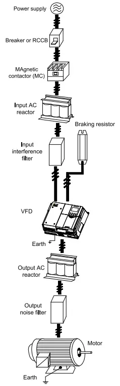
Peripheral wiring
Figure2-1 Peripheral equipment connection
Terminal function
3.1 Main circuit terminal diagram
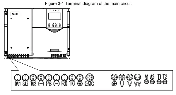
Table 3-1 Main circuit terminals
| Terminal symbol | Terminal name | Function |
| R/L1, S/L2, T/L3 | Main circuit power input | Connect R, S, T terminals when the input is 3PH AC 380V. Connect L1, L2, L3 terminals when the input is 3PH AC 220V. Connect any two of L1, L2, L3 terminals when the input is single phase AC 220V. |
| (+), PB | Reserved terminals to connect to the external braking resistor | Reserved terminals to connect to the external braking resistor |
| (-) | DC negative bus output terminal | DC negative bus output terminal |
| RO, TO | Emergency power main power input port | When using the emergency rescue function, DC48V or AC220V power can be input. |
| Al, A2 | Emergency power auxiliary power input port | When using the emergency rescue function normally, UPS AC220V power can be connected. |
| T1, T2 | Inspection input port | For equipment maintenance and debugging in the case of main power failure. AC220V power supply can be connected. |
| U, V, W | VFD outputs | 3PH AC output terminals, which connect to the motor in most cases |
| OGrounding terminal | Grounding terminal |
3.2 Control circuit wiring diagram
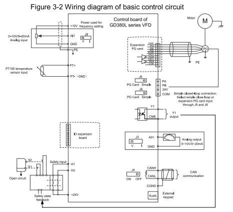
Table 3-2 Control circuit terminals
| Terminal name | Description |
| +24V | Used to provide input digital working power from the internal to the external Capacity: 200mA |
| COM | +24V common terminal |
| Y1 | 1. Switch capacity: 50mA/30V 2. Output frequency range: 0-1kHz |
| CME | Common terminal of open collector output |
| PA11 | Encoder interface 1. Applicable to 24V push-pull, OC encoders 2. Response frequency: 100kHz |
| P13(1) | |
| PT+ | PT100 interface 1. Resolution: 1°C 2. Range: -20°C-150°C 3. Detection precision: ±3°C |
| PT- | |
| +10V | Used to externally provide 10V reference power supply. Max. output current: 50mA. Generally used as the regulation power supply of the external potentiometer whose impedance is greater than 5k0. |
| GND | Reference zero potential |
| All | 1. Input range: For Al, 0-10V/0-20mA. All is switched by jumper J8. 2. Input impedance: 20k0 for voltage input or 5000 for current input. 3. Resolution: 5mV when 10V corresponds to 50Hz. 4. Error: ±1% at 25°C |
| GND | Reference zero potential of +10V |
| A01 | 1. Output range: 0-10V or 0-20mA 2. Whether voltage or current is used for output is set through the jumper J3. 3. Resolution: 10mV when 10V corresponds to 50Hz. |
| CANN | CANopen communication interface |
| CANL | |
| +24V | STO function input terminal |
| H1 | |
| +24V | |
| H2 |
Note:
- When jumper cap J5/J6 is shorted to Simple, a simple closed-loop control can be achieved.
- RJ45 is an external keypad interface. It is recommended to use standard RJ45 connectors with short body.
3.3 Terminal block circuit wiring diagram
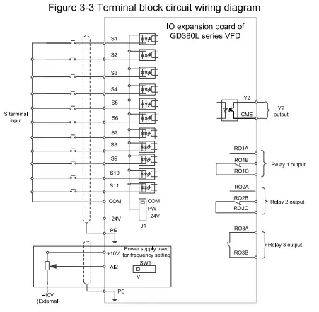
Table 3-3 Terminal block circuit terminals
| Terminal name | Description |
| S1-511 | Regular digital input terminal 1. Internal impedance: 3.3k0 2. 12-30V voltage input is acceptable. 3. Bi-direction input terminal, supporting both NPN and PNP 4. Max. input frequency: 1kHz 5. All of them are programmable digital input terminals. Users can set the terminal function by function code. |
| COM | +24V common terminal |
| Al2 | 1. Input range: For Al2, 0-10V/0-20mA. Al2 is switched by DIP switch SW1. 2. Input impedance: 20k0 for voltage input or 5000 for current input 3. Resolution: 10mV when 5mV corresponds to 50Hz. 4. Error: ±1% at 25°C |
| GND | Reference zero potential of +10V |
| Y2 | 1. Switch capacity: 50mA/30V 2. Output frequency range: 0-1kHz |
| CME | Common terminal of open collector output |
| RO1A | RO1 output; RO1A: NO; RO1B: NC; RO1C: common Contact capacity: 3A/AC250V, 1A/DC3OV |
| RO16 | |
| RO1C | |
| RO2A | RO2 output; RO2A: NO; RO2B: NC; RO2C: common Contact capacity: 3A/AC250V, 1A/DC3OV |
| RO26 | |
| RO2C | |
| RO3A | RO3 output. RO3A: NO; RO3C: NC Contact capacity: 3A/AC250V, 1A/DC3OV |
| RO3C |
Quick startup
4.1 Check before power-on
| Ensure that all terminals have been securely connected. | |
| Ensure that the motor power matches the VFD power. |
4.2 First power-on
After confirming the wiring and power are correct, close the air switch of the AC power supply at the VFD input side to power on the VFD. The keypad displays as the following figure, indicating that the VFD is ready for run.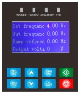
The quick startup diagram is as follows:

Keypad
Table 5-1 LCD keypad
| No. | Item | Description | |
| 1 | Status indicator | RUN/TUNE | Off: The VFD is stopped. On: The VFD is running. |
| FWD/REV | Forward or reverse running indicator Off: The VFD is running forward. On: The VFD is running reversely. | ||
| No. | Item | Description | ||
LOCAUREMOT | Indicates whether the VFD is controlled through the keypad, terminals, or communication. Off: The VFD is controlled through the keypad. Blinking: The VFD is controlled through terminals. On: The VFD is controlled through remote communication. | |||
TRIP | Fault indicator On: The VFD is in fault state. Off: The VFD is in normal state. | |||
| 2 | Keys |  | Programming key | Press it to enter or exit level-1 menus |
 | Confirmation key | Press it to enter menus in cascading mode or confirm the setting of a parameter. | ||
 | UP key | Press it to increase data or move upward. | ||
 | Down key | Press it to decrease data or move downward. | ||
 | Right-shifting key | Press it to select display parameters rightward in the interface for the VFD in stopped or running state or to select digits to change during parameter setting. | ||
 | Run key | Press it to run the VFD when using the keypad for control. | ||
 | Stop/Reset key | Press it to stop the VFD that is running. The function of this key is restricted by P07.05. In fault alarm state, this key can be used for reset in any control modes. | ||
 | Multifunction shortcut key | The function is determined by P07.04. | ||
Common function parameters
6 Common function parameters
The following table briefly describes some common function parameters and typical values.
“0” indicates that the value of the parameter can be modified when the VFD is in stopped or running state.
“©” indicates that the value of the parameter cannot be modified when the VFD is in running state.
“•” indicates that the value of the parameter is detected and recorded, and cannot be modified.
(The VFD automatically checks and constrains the modification of parameters, which helps prevent incorrect modifications.)
| Function code | Name | Description | Default | Modify |
| P00.00 | Speed control mode | 0: Sensorless vector control (SVC) 0 1: SVC 1 2: Reserved 3: Closed-loop vector control | 0 | |
| P00.01 | Channel of running commands | 0: LED keypad (the indicator is off) 1: Terminal (the indicator blinks) 2: LCD keypad (the indicator is off) 3: CAN (the indicator is on) 4: CANopen (the indicator is on) | 1 | |
| P00.02 | Rated speed of the elevator | 0‘100-4.000m/s | 1.000m/s | |
| P00.03 | Speed command selection | 0: Keypad 1: All 2: Al2 3: Multi-step speed running 4: Remote communication 5: All tracking running 6: CAN communication-based setting 7: CAN communication-based reference 8: CANopen communication-based setting 9: CANopen communication-based reference | 3 | |
| P00.04 | Max. output frequency | 1.00-600.00Hz | 50.00Hz | |
| P00.05 | Speed set through keypad | 0.00Hz—P00.02 (Rated speed of the elevator) | 0.00Hz | 0 |
| P00.06 | Running direction | 0: Run at the default direction. 1: Run at the opposite direction. 2: Disable reverse running | 0 | |
| P00.07 | Carrier frequency | 0: Fixed carrier frequency. The VFD runs at the carrier frequency set in P00.08. 1: Automatic regulation | 0 | |
| P00.08 | Carrier frequency setting | 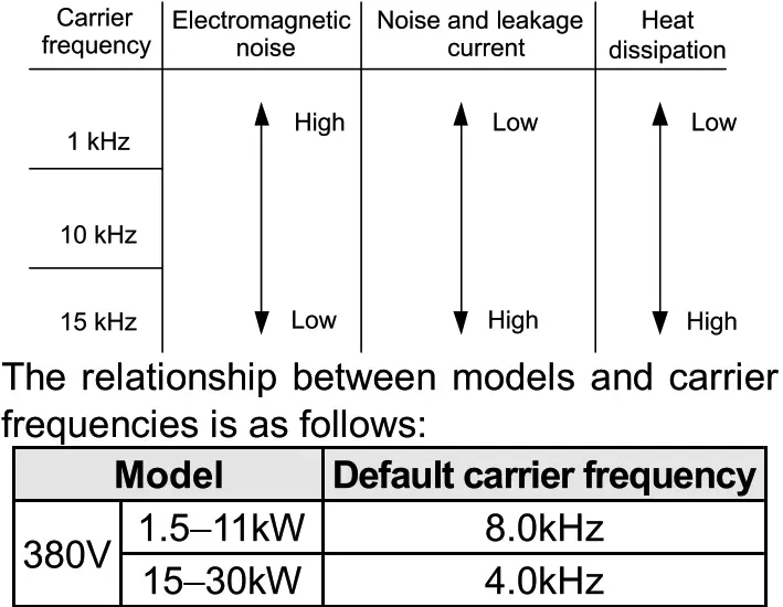 | 8.0kHZ |
| Function code | Name | Description | Default | Modify |
| Advantage of high carrier frequency: ideal current waveform,little current harmonic wave and motor noise. Disadvantage of high carrier frequency: increasing the switch loss, increasing VFD temperature and the impact to the output capacity. The VFD needs to derate on high carrier frequency. At the same time, the leakage and electrical magnetic interference will increase. On the contrary, an extremely-low carrier frequency may cause unstable operation at low frequency, decrease the torque, or even lead to oscillation. The carrier frequency has been properly set in the factory before the VFD is delivered. In general, you do not need to modify it. When the frequency used exceeds the default carrier frequency, the VFD needs to derate by 20% for each increase of 1k carrier frequency. Setting range: 1.0-16.0kHz | ||||
| P00.09 | Motor parameter autotuning | 0: No operation 1: Rotating parameter autotuning on empty-load asynchronous motor 2: Static parameter autotuning on asynchronous motor 3: Rotating parameter autotuning on empty-load synchronous motor 4: Static parameter autotuning on synchronous motor 5: Rotating parameter autotuning on synchronous motor with load | 0 | 0 |
| P00.10 | Function parameter restore | 0: No operation 1: Restore default values 2: Clear fault records 3. Roll back function parameters, reading function parameters that are saved when the LSB of P07.01 is set to 5. | 0 | |
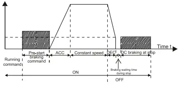
| P01.00 | Start mode | 0: Start-up directly: start from the starting frequency P01.01 1: Start-up after DC braking: start the motor from the starting frequency after DC braking (setting P01.04 and P01.05) It is suitable in the cases where reverse rotation may occur to the low inertia load during starting. | 0 | |
| P01.07 | Stop mode | 0: Decelerate to stop. After the stop command becomes valid, the VFD decelerates to decrease the output frequency during the set time. When the frequency decreases to the stop speed, the VFD stops. 1: Coast to stop: after the stop command becomes valid, the VFD ceases the output immediately. And the load coasts to stop at the mechanical inertia. And the load coasts to stop according to mechanical inertia. | 0 | 0 |
| P01.08 | Starting frequency of DC braking for stop | Starting frequency of DC braking for stop: During the deceleration to stop, the VFD starts DC braking for stop when running frequency reaches the starting frequency determined by P01.09. Wait time before DC braking: The VFD blocks the output before starting DC braking. After this wait time, DC braking is started so as to prevent overcurrent caused by DC braking at high speed. DC braking current for stop: It indicates the applied DC braking energy. Stronger current indicates greater DC braking effect. | 0.00Hz | 0 |
| P01.09 | Demagnetizati on time | “Os | 0 | |
| P01.10 | DC braking current for stoa, DC braking time for stop | 0.0% | 0 | |
| P01.11 | 0.0s | 0 | ||
| P02.00 | Motor type | 0: Asynchronous motor (AM) 1: Synchronous motor (SM) | 0 | 0 |
| P02.01 | Motor rated power | 0.1-3000.0kW | Model depended | 0 |
| P02.02 | Motor rated frequency | 0.01 Hz—P00.04 (Max. frequency) | 50.00Hz | 0 |
| P02.03 | Motor rated speed | 1-36000rpm | Model depended | 0 |
 Setting range of P01.08: 0.00Hz—P00.04 (Max. output frequency)
| Function code | Name | Description | Default | Modify |
| P02.04 | Motor rated voltage | 0-1200V | Model depended | 0 |
| P02.05 | Motor rated current | 0.8-6000.0A | Model depended | 0 |
| P02.06 | Stator resistance of AM | 0.001-65.5350 | Model depended | |
| P02.07 | Rotor resistance of AM | 0.001-65.5350 | Model depended | 0 |
| P02.08 | Leakage inductance of AM | 0.1-6553.5mH | Model depended | |
| P02.09 | Mutual inductance of AM | 0.1-6553.5mH | Model depended | |
| P02.10 | No-load current of AM | 0.1-6553.5A | Model depended | 0 |
| P02.11 | Direct-axis inductance of SM | 0.01-655.35mH | Model depended | 0 |
| P02.12 | Quadrature-axis inductance of SM | 0.01-655.35mH | Model depended | 0 |
| P02.13 | CountS er-emf of M | 0-10000V | 320V | 0 |
| P02.14 | Pulley diameter | 100-2000m | 500mm | 0 |
| P02.15 | DEC ratio | 0.50-50.00 | 1.00 | 0 |
| P02.16 | Speed ratio | 0-65535 | 1000 | 0 |
| P05.01 | Function of Si terminal | 0: No function 1: Up running (FWD) 2: Down running (REV) 3: Running in inspection (EXM) 4: Emergency operation (EMER) 5: Coast to stop (FSTP) 6: Fault reset (RET) 7: External fault (EF) 8: Multi-step speed terminal 1 (MS1) 9: Multi-step speed terminal 2 (MS2) 10: Multi-step speed terminal 3 (MS3) 11: Up forced DEC 1 (UFS1) 12. Up forced DEC 2 (UFS2) 13: Up forced DEC 3 (UFS3) 14. Down forced DEC 1 (DFS1) 15: Down forced DEC 2 (DFS2) 16. Down forced DEC 3 (DFS3) 17: Contactor feedback signal (TB) 18: Brake feedback signal (FB) 19: VFD enabling (ENA) 20: Forced decelerate to stop 21: Emergency mode 22. Motor overheating 23: Main power supply input disconnected (for India) 24: UPS input disconnected by main control (for India) 25: Base lockout 26: Leveling signal 27-40: Reserved | 0 | 0 |
| P05.02 | Function of S2 terminal | 1 | ||
| P05.03 | Function of S3 terminal | 2 | ||
| P05.04 | Function of S4 terminal | 8 | ||
| P05.05 | Function of S5 terminal | 9 | ||
| P05.06 | Function of S6 terminal | 10 | 0 | |
| P05.07 | Function of S7 terminal | 0 | 0 | |
| P05.08 | Function of S8 terminal | 4 | 0 | |
| P05.09 | Function of S9 terminal | 0 | 0 | |
| P05.10 | Function of 510 terminal | 0 | 0 | |
| P05.11 | Function of S11 terminal | 0 | 0 | |
| P05.12 | Reserved | 0 | 0 | |
| P05.13 | Input terminal polarity | The function code is used to set the polarity of input terminals. When a bit is 0, the input terminal is positive; when a bit is 1, the input terminal is negative. 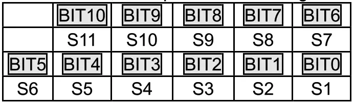 Setting range: 0x000-0x7FF Setting range: 0x000-0x7FF | Ox000 | 0 |
| P05.14 | Digital input filter time | The function code is used to specify the filter time of S1-S11 terminal sampling. In strong interference cases, increase the value to avoid maloperation. 0.000-1.000s | 0.002s | 0 |
| P05.16 | Enable power-on terminal detection | 0: Disable 1: Enable (terminal command power-on response and terminal command response to UV fault rectification) | 1 | 0 |
| P06.01 | Y1 output | 0: No output 1: Lift in operation 2: Up operation 3: Down running 4: Fault output 5: Running at zero speed 6: Ready for running 7: Brake control 8: Contactor control 9: Frequency reached 10: Frequency level detection FDT output 11: Reserved 12: Reserved 13: Light-load direction detection completed 14: Down as the light-load direction detection result | 1 | 0 |
| P06.02 | Y2 output selection | 0 | 0 | |
| P06.03 | Relay output RO1 | 0 | 0 | |
| P06.04 | Relay output RO2 | 7 | 0 | |
| P06.05 | Relay output RO3 | 8 | 0 |
| Function code | Name | Description | Default | Modify |
| 15: Up as the light-load direction detection result 16: Running 1 (excluding current withdrawal) 17: STO action 18: SPI fault output 19: UPS control signal output (India) 20: Sealed-star output 21: Waiting after autonomous rescue leveling | ||||
| P06.07 | Output terminal polarity selection | The function code is used to set the polarity of output terminals. When the current bit is set to 0, the output terminal is positive. When the current bit is set to 1, the output terminal is negative.  Setting range: 0x00-0x1F | Ox00 | 0 |
| P06.08 | A01 output | 0: Running speed 1. Set speed 2: Rotational speed 3: Output Current 4: Output voltage 5: Output power 6: Output torque 7: All input 8: Al2 input | 0 | 0 |
| P07.01 | Parameter copy | Ones place: 0: No operation 1: Upload parameters from the local address to the keypad 2: Download parameters (including motor parameters) from the keypad to the local address 3: Download parameters (excluding group P02) from the keypad to the local address 4: Download parameters (including only motor parameters of P02) from the keypad to machine. 5:Save parameters (including motor parameters) of the machine Note: After any operation among 1-5 is complete, the parameter restores to 0. Tens place: Reserved Thousands place: Indicates the response speed of the keypad. 0: Low speed 1: Medium speed 2: High speed | Ox100 | 0 |
| P09.00 | Multi-step speed 0 | 0.000m/s-P00.02 | 0.080m/s | 0 |
| P09.01 | Multi-step speed 1 | 0.000m/s-P00.02 | 0.700m/s | 0 |
| P09.02 | Multi-step speed 2 | 0.000m/s-P00.02 | 0.180m/s | 0 |
| P09.03 | Multi-step speed 3 | 0.000m/s-P00.02 | 0.300m/s | 0 |
| P09.04 | Multi-step speed 4 | 0.000m/s-P00.02 | 0.000m/s | 0 |
| P09.05 | Multi-step speed 5 | 0.000m/s-P00.02 | 0.000m/s | 0 |
| P09.06 | Multi-step speed 6 | 0.000m/s-P00.02 | 0.000m/s | 0 |
| P09.07 | Multi-step speed 7 | 0.000m/s-P00.02 | 0.000m/s | |
| P09.08 | Multi-step speed priority | 0: CHINESE TYPE 1: ISTANBUL TYPE 2: KONYA TYPE 3: ADANA TYPE | 0 | 0 |
| P09.09 | ACC time | 0.1-360.0s | 2.0s | 0 |
| P09.10 | DEC time | 0.1-360.0s | 2.0s | |
| P09.11 | S-curve ACC start segment duration | 0.1-360.0s | 2.0s | 0 |
| P09.12 | S-curve ACC end segment duration | 0.1-360.0s | 2.0s | 0 |
| P09.13 | S-curve DEC start segment duration | 0.1-360.0s | 2.0s | |
| P09.14 | S-curve DEC end segment duration | 0.1-360.0s | 2.0s | |
| P09.15 | S-curve start segment duration during stop | 0.1-360.0s | 2.0s | 0 |
| P09.16 | S-curve end segment duration during stop | 0.1-360.0s | 2.0s | 0 |
| Function code | Name | Description | Default | Modify | ||||||
| P09.17 | Running speed at maintenance | 0.001m/s—P00.02 | 0.200m/s | 0 | ||||||
| P09.18 | ACC/DEC time at maintenance | 0.1-360.0s | 4.0s | 0 | ||||||
| P09.19 | Forced DEC time | 0.0-360.0s | 0.0s | 0 | ||||||
| P09.20 | Emergency running speed | 0.001m/s—P00.02 | 0.100m/s | 0 | ||||||
| P09.21 | Emergency ACC/DEC time | 0.1-360.0s | 20.0s | 0 | ||||||
| P09.22 | Leveling segment | 0-7 | 0 | 0 | ||||||
| P09.23 | Leveling speed | 0.001m/s—P00.02 | 0.010m/s | 0 | ||||||
| P09.24 | DEC time for creeping to stop | 0.1-360.0s During deceleration to stop, when the speed reached the value set in P01.12, the curve of deceleration to stop switches to those set in P09.15, P09.16, and P09.24. | 2.0s | 0 | ||||||
| P09.25 | Speed threshold for light-load detection in open-loop control | 5.00-20.00Hz | 5.00Hz | 0 | ||||||
| P11.00 | Protection against phase loss | Ox000-0x111 Ones place: 0: Protection against input phrase loss disabled 1: Protection against input phrase loss enabled Tens place: 0: Protection against output phrase loss disabled 1: Protection against output phrase loss enabled LED hundreds place: 0: Hardware input phrase loss protection disabled 1: Hardware input phrase loss protection enabled | Ox110 | 0 | ||||||
| P11.01 | Frequency drop at transient power-off | 0: Disable 1: Enable | 0 | 0 | ||||||
| P11.02 | Frequency drop rate at transient power-off | Setting range: 0.00Hz/s—P00.04 (max. output frequency) After the power loss of the grid, the bus voltage drops to the sudden frequency-decreasing point, the VFD begin to decrease the running frequency at P11.02, to make the VFD generate power again. The returning power can maintain the bus voltage to ensure a rated running of the VFD until the recovery of Power.
Note: | 10.00 Hz/s | |||||||
| P11.03 | Overvoltage stalling protection | 0: Disable 1: Enable | 0 | 0 | ||||||
| P11.04 | Overvoltage stalling protection voltage | 120-145% (standard bus voltage) (380V) | 136% | 0 | ||||||
| 120-145% (standard bus voltage) (220V) | 120% | |||||||||
| P11.05 | Current limit action | During accelerated running, as the load is too large, the actual acceleration rate of motor is lower than that of output frequency, if no measures are taken, the VFD may trip due to overcurrent during acceleration. Ones place: Current limit action 0: Invalid 1: Always valid | 0 | 0 | ||||||
| P11.06 | Automatic current limit threshold | Current-limit protection function detects output current during running, and compares it with the current-limit level defined by P11.06, if it exceeds the current-limit level, the VFD will run at stable frequency during accelerated running, or run in decreased frequency during constant-speed running; if it exceeds the current-limit level continuously, the VFD output frequency will drop continuously until reaching lower limit frequency. When the output current is detected to be lower than the current-limit level again, it will continue accelerated running.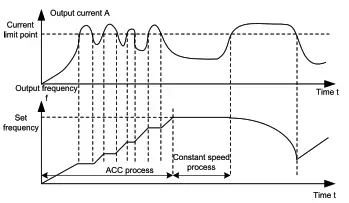 Setting range of P11.06: 50.0-200.0% (of the VFD rated output current) Setting range of P11.06: 50.0-200.0% (of the VFD rated output current)Setting range of P11.07: 0.00-50.00Hz/s | 160.0% | 0 | ||||||
| P11.07 | Frequency drop rate during current limit | 10.00 Hz/s | 0 |
| Function code | Name | Description | Default | Modify |
| P11.20 | STO function selection | Ones place: 0: STO function disabled 1: STO function enabled Tens place: 0: Alarm locked (the SAFE fault can be reset manually) 1: Alarm not locked (the SAFE fault can be reset automatically) | 0x01 | 0 |
| P15.27 | CAN/CANopen communication baud rate | 0: 1000kbps 1: 800kbps 2: 500kbps 3: 250kbps 4: 125kbps 5: 100kbps 6: 50kbps 7: 20kbps | 3 | |
| P15.28 | CAN/CANopen communication address | 0-127 | 1 | O |
| P20.00 | Encoder type selection | 0: Incremental encoder (AB) 1: ABZUVW encoder 2: Resolver-type encoder 3: Sin/Cos encoder without CD signals 4: Sin/Cos encoder with CD signals 5: EnDat absolute encoder | 0 | 0 |
| P20.01 | Encoder pulse count | Number of pulses generated when the encoder revolves for one circle. Setting range: 0-60000 | 1024 | © |
| P20.02 | Encoder direction | Ones place: AB direction 0: Forward 1: Reverse Tens place: Reserved Hundreds place: CD/UVW pole signal direction 0: Forward 1: Reverse | Ox000 | 0 |
| P20.06 | Speed ratio between encoder mounting shaft and motor | You need to set the function parameter when the encoder is not installed on the motor shaft and the drive ratio is not 1. Setting range: 0.001-65.535 | 1.000 | 0 |
| P20.09 | Initial angle of Z pulse | Relative electric angle between the encoder Z pulse and the motor pole position. Setting range: 0.00-359.99 | 0.00 | 0 |
| P20.10 | Pole initial angle | Relative electric angle between the encoder position and the motor pole position. Setting range: 0.00-359.99 | 0.00 | 0 |
Common faults and solutions
This chap er briefly describes some common faults and the solutions.
| Fault code | Fault type | Possible cause | Solution |
| OUt1 | 111 Inverter unit U-phase protection | ACC is too fast. IGBT module is damaged. Misoperation caused by interference. Drive wires are poorly connected. To-ground short circuit occurs. | Increase ACC time. Replace the power unit; Check drive wires; Check whether there is strong interference surrounding the peripheral device. |
| OUt2 | [2] Inverter unit V-phase protection | ||
| OUt3 | [3] Inverter unit W-phase protection | ||
| OV1 | [7] Overvoltage during ACC | Exception occurred to input voltage. Large energy feedback; Lack of braking units; Energy-consumption braking is not enabled. | Check the input power. Check whether load DEC time is too short or the motor starts during rotating; Install dynamic brake components. Check the setting of related function codes. |
| OV2 | [8] Overvoltage during DEC | ||
| OV3 | [9] Overvoltage during constant speed running | ||
| 0C1 | [4] Overcurrent during ACC | ACC/DEC is too fast; The voltage of the grid is too low; VFD power is too small. Load transient or exception occurred. To-ground short circuit or output phase loss occurred; Strong external interference sources; The overvoltage stall protection is not enabled. Phase loss on output side. | Increase ACC/DEC time. Check the input power; Select the VFD with larger power; Check whether the load is short circuited (to-ground short circuit or line-to-line short circuit) or the rotation is not smooth. Check the output wiring; Check if there is strong interference; Check the related function code settings. Check whether phase loss occurred on output side. |
| 0C2 | [5] Overcurrent during DEC | ||
| 0C3 | [6] Overcurrent during constant speed running | ||
| UV | [10] Bus undervoltage | The voltage of the grid is too low. The overvoltage stall protection is not enabled. | Check the grid input power supply. Check the setting of related function codes. |
| OL1 | [11] Motor overload | The voltage of the grid is too low. The motor rated current is set incorrectly. The motor stall occurs or the load transient is too large. | Check the grid voltage. Reset the motor rated current. Check the load and adjust the torque boost quantity. |
| OL2 | [12] VFD overload | ACC is too fast. The motor in rotating is restarted. The voltage of the grid is too low. Load too large. The motor power is too large. | Increase ACC time. Avoid restart after stop. Check the grid voltage; Select the VFD with larger power; Select a proper motor. |
| Fault code | Fault type | Possible cause | Solution |
| SPI | [13] Phase loss on input side | Phase loss or violent fluctuation occurred on input R, S, T. | Check the input power. Check the installation wiring. |
| SPO | [14] Phase loss on output side | Phase loss output occurs to U, V, W (or the three phases of the load are seriously asymmetrical). | Check the output wiring. Check the motor and cable. |
| OH1 | [15] Rectifier module overheating | Air duct is blocked or fan is damaged. Amb hige temperature is too Long-time overload running. | Ventilate the air duct or replace the fan. Lower the ambient temperature. |
| OH2 | [16] Inverter module overheat | ||
| EF | [17] External fault | SI external faulty input terminal action. | Check external device input. |
| CE | [18] RS485 communication fault | Incorrect baud rate. Communication line fault; Incorrect communication address. Communication suffers from strong interference. | Set proper baud rate; Check the wiring of communication interfaces; Set the proper communication address. Replace or change the wiring to enhance the anti-interference capacity. |
| HE | [19] Current detection fault | Poor contact of the connector of control board. Hall component is damaged. Exception occurred to amplification circuit. | Check the connector and re-plug; Replace the hall component. Replace the main control board. |
| tE | [20] Motor autotuning fault | The motor capacity does not match the VFD capacity. Motor parameter is set improperly. The parameters gained from autotuning deviate sharply from the standard parameters; Autotuning timeout. | Change the VFD model. Set proper motor type and nameplate parameters. Empty the motor load and carry out autotuning again. Check the motor wiring and parameter setup; Check whether the upper limit frequency is larger than 2/3 of the rated frequency. |
| EEP | [21] EEPROM operation fault | Error in reading or writing control parameters. EEPROM is damaged. | Press STOP/RST to reset. Replace the main control board. |
| PIDE | [22] PID feedback offline fault | PID feedback offline. PID feedback source disappears. | Check PID feedback signal wires; Check PID feedback source. |
| bCE | [23] Braking unit fault | Fault occurred to the brake circuit or the braking pipe is damaged. Resistance of the external braking resistor is small. | Check the braking unit, and replace with new braking pipe; Increase the brake resistance. |
| END | [24] Running time reached | The actual running time of the VFD is longer than the internal set running time. | Ask for the supplier and adjust the set running time. |
| OL3 | [25] Electronic overload fault | The VFD reports overload pre-alarm according to the setting. | Check the load and the overload pre-alarm points. |
| PCE | [26] Keypad communication fault | Keypad cable connected improperly or disconnected. Keypad cable too long, causing strong interference. Keypad or mainboard communication circuit error. | Check the keypad cable to determine whether a fault occurs. Check for and remove the external interference source. Replace the hardware and seek maintenance services. |
| UPE | [27] Parameter upload error | Keypad cable connected improperly or disconnected. Keypad cable too long, causing strong interference. Keypad or mainboard communication circuit error. | Check for and remove the external interference source. Replace the hardware and seek maintenance services. Replace the hardware and seek maintenance services. |
| DNE | [28] Parameter download error | Keypad cable connected improperly or disconnected. Keypad cable too long, causing strong interference. Data storage error occurred to the keypad. | Check for and remove the external interference source. Replace the hardware and seek maintenance services. Re-back up the data on the keypad. |
| E-DP | [29] PROFIBUS communication fault | Communication address is not correct. The matching resistance is not set well. The master GSD file is not set up. The peripheral interference is too large. | Check the related settings; Check the surrounding environment, and eliminate interference effects. |
| E-NET | [30] Ethernet communication fault | The address of Ethernet is set improperly. The communication mode is set improperly. The peripheral interference is too large. | Check the related settings; Check the communication mode selection; Check the surrounding environment, and eliminate interference effects. |
| E-CAN | [31) CANopen communication fault | Line contact is poor. The matching resistor is not switched on. Communication baud rates do not match. The peripheral interference is too large. | Check the line: switch on the matching resistor. Set the same baud rate; Check the surrounding environment, and eliminate interference effects. |
| ETH1 | [32] To-ground short-circuit fault 1 | VFD output is short connected to the ground. There is a fault in the current detection circuit. | Check whether the motor wiring is normal. Replace the hall component; Replace the main control board. |
| ETH2 | [33] To-ground short-circuit fault 2 | VFD output is short connected to the ground. | Check whether the motor wiring is normal. |
| Fault code | Fault type | Possible cause | Solution |
| There is a fault in the current detection circuit. | Replace the hall component; Replace the main control board. | ||
| dEu | [34] Speed deviation fault | The load is too heavy or stalled. | Check the load to ensure it is proper, and increase the detection time; Check whether the control parameters are set properly. |
| STo | [35] Mal-adjustment fault | Control parameters of the synchronous motor is set improperly. Autotuned parameters are not accurate; The VFD is not connected to the motor. | Check the load and ensure the load is normal. Check whether control parameters are set correctly. Increase the mal-adjustment detection time. |
| LL | [36] Electronic underload fault | The VFD reports underload pre-alarm according to the setting. | Check the load and the underload pre-alarm points. |
| ENC1O | [37] Encoder disconnection fault | Incorrect encoder wiring, causes the failure to get the encoder signal. Incorrect encoder parameter settings. | Check the wiring. Check encoder parameter settings. |
| ENC1D | [38] Encoder reserve-rotation fault | Incorrect encoder signal direction. | Set the function code to change the direction or reverse the AB signal wires. |
| ENC1Z | [39] Encoder Z-pulse disconnection fault | The Z-pulse signal cable is not connected. | Check the Z-pulse signal cable. |
| ENC1U | [40] U disconnection | There are no U, V, or W signals or there is interference. | Check the U, V, and W signal wiring. |
| OT | [43] Motor overtemperature fault | Motor overtemperature signal. | |
| BAE | [45] Brake fault | Brake signal and control signal are inconsistent. Feedback terminal signal is interfered. | Check whether the brake is in good condition. Check feedback terminal signal. |
| CONE | [46] Contactor fault | Brake signal and control signal are inconsistent. Feedback terminal signal is interfered. | Check whether the contactor is in good condition. Check feedback terminal signal. |
| nPoS | :47] CD signal unavailable | The sine-cosine or absolute-value encoder position signal is lost. The encoder is interfered. | Check whether the encoder is in good condition. Check whether the VFD and encoder are grounded. |
| SAFE | [49] STO card fault | The STO card safety circuit does not work. The expansion card type is incorrect. | Check whether the STO cardis in good condition. Check whether the expansion card type is correct. |
| STL1 | [50] STO card circuit 1 exception | Circuit 1 of the STO card does not work. | Check whether the STO card is in good condition. Check circuit 1 of the STO card. |
| STL2 | [51] STO card circuit 2 exception | Circuit 2 of the STO card does not work. | Check whether the STO card is in good condition. Check circuit 2 of the STO card. |
| STL3 | [52] STO internal circuit exception | The internal circuits of the STO card do not work. | Check whether the circuits of the VFD control board is in good condition. |
| CrCE | [53] Safety code CRC exception | Exceptions occur in the verification of the safety circuit code. | Check whether the control board is in good condition. |
| bOC | [54] Braking pipe overcurrent fault | Braking pipe resistance is unmatched. | Check the resistance of braking pipe. |
| bOL | [55] Braking pipe overload | Braking pipe resistance is unmatched. The device is in the energy feedback state for long period. | Check the resistance of braking pipe. Check the operating conditions. |
| C2-Er | [64] Expansion card communication fault | Expansion card is connected improperly. Expansion card is damaged. | Check the expansion card connection. Check whether the expansion card is in good condition. |
More information
Please contact us for any information about the products. It is necessary to provide the product model and serial number during consultation.
To obtain more information, you can: Contact INVT local office. Visit www.invt.com or scan the QR code of INVT.


![]() Manual information may be subject to change without prior notice. 202208(V1.0)
Manual information may be subject to change without prior notice. 202208(V1.0)


