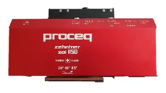
Proceq ZOL1150 Inline Glossmeter  Legal Notices
The content of this document is the intellectual property of Proceq SA.
This document can be changed at every time and without any prenotification or announcement.
The content of this document is the intellectual property of Proceq SA and prohibited to be copied neither in a photomechanical or electronic way, nor in excerpts, saved and/or be passed on to other persons and institutions.
The features described in this instruction manual represent the complete technology of this instrument. These features are either included in the standard delivery or available as options at additional costs.
The content of this document is the intellectual property of Proceq SA.
Illustrations, descriptions, as well as technical specifications, conform to the instruction manual on hand at the time of publishing or printing. However, Proceq SA policy is one of continuous product development. All changes resulting from technical progress, modified construction or similar are reserved without obligation for Proceq SA to update.
Some of the images shown in this instruction manual may be of a pre-production model and/or are computer generated. Therefore, the design / features of the delivered product may differ in various aspects.
The instruction manual has been drafted with the utmost care. Nevertheless, errors cannot be entirely excluded. The manufacturer will not be liable for errors in this instruction manual or for damages resulting from any errors.
The manufacturer will be grateful at any time for suggestions, proposals for improvement and indications of errors.
Damages during carriage
On receipt of the goods, check for any visible damages on the packaging. If it is undamaged, you may sign the receipt of the goods. If you do suspect by visual inspection that damage has occurred, make a note of the visible damage on the delivery receipt and request the courier to countersign it. Moreover, the courier service must be held responsible for the damage in writing.
If a hidden damage is discovered while unpacking, you have to inform and hold the courier liable immediately in the following way: “When opening the parcel we had to notice that … etc.“ This superficial checking of the goods has to be done within the time limit set by the carrier, which is normally 7 days. However, the period could vary depending on the courier. Hence, it is recommended to check the exact time limit when receiving the goods.
If there are any damages also inform your authorized Proceq agent or Proceq SA immediately.
Shipment
Should the device be transported again, it must be packaged properly. Preferably use the original packaging for later shipments. Additionally, use filling material in the package to protect the device from any shock during carriage.
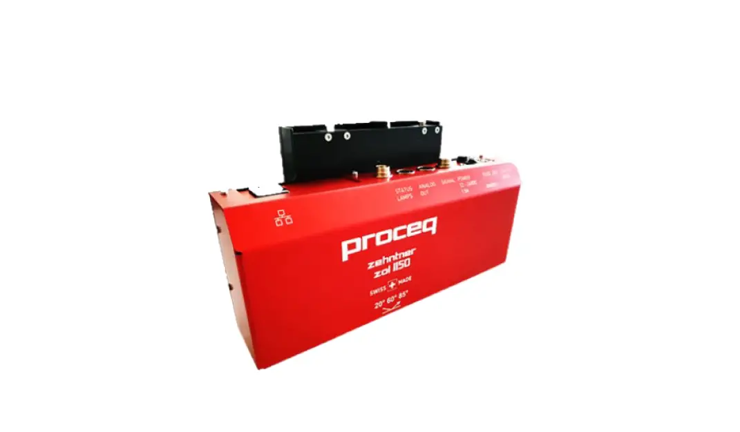
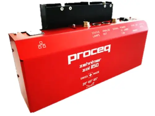
Introduction
The ZOL 1150 is a tailored gloss-measuring system for industrial areas for contactless online measurement of all gloss ranges from matt to high gloss up to 2‘000 GU.
Application areas
- Measuring instrument for several industries such as paint, plastics, paper, foil and metal industry
- For all gloss measurements
- Gloss measurement at manufacturing of sheet metal and floor coverings
- Finishing processes such as application of coating of all types, e.g. coil coating Combinable with other quality monitoring systems, e.g. humidity, thickness etc.
Key features
This apparatus has the following features:
- Multi angle device, up to three angles in the same device
- Pathbreaking with various types of digital communication interfaces (Ethernet) and analog outputs
- Unique automatic in-situ calibration simplifies handling and minimizes holding times significantly
- Automatic measuring distance correction
- Online monitoring of gloss during the production with up to 1‘000 measurements per second
- Integrated Z-axis
- Powerful stray light compensation allows exact measurements of transparent objects Analog output of measuring value: 0-10 V, 0-20 mA or 4-20 mA
- Possibility to control the unit over digital inputs, this means the possibility of (signal input for calibration and moving measuring head)
- Signal outputs for alerts
- Reliable results
Versions
The ZOL1150 is available in two versions:
- ZOL1150.268
- Triple Angle device, 20°/60°/85°
- ZOL1150.26
- Triple Angle device, 20°/60°
Scope of this document
This document is an instruction manual for the ZOL1150 Inline Glossmeter.
It describes in technical details, the mounting and explains the connection setup, the protocol format, the command set and their parameters, the answer-strings of the device as well as possible error reports.
Safety information
Symbols used
- This note comprises instructions needed to follow directions, specifications, proper working procedure and to avoid data loss, damage or destruction of the instrument.
- This note signifies a warning about dangers to life and limb if the apparatus is handled improperly. Observe these notes and be particularly careful in these cases. Also inform other users on all safety notes. Besides the notes in this instruction manual the generally applicable safety instructions and regulations for prevention of accidents must be observed.
Safety notes and hints
- It is strictly forbidden to open the housing of the ZOL 1150. If not observed, all the guarantee and liability claims will be void.
- The ZOL 1150 is a high quality, state of the art instrument and is safe to operate. However, there is always risk when the instrument is handled improperly or otherwise as intended by the manufacturer.
- Always turn off the unit and unplug the power cable before any maintenance.
- The ZOL 1150 is exclusively intended for contactless online measurement of all gloss ranges from matt to high gloss up to 2‘000 GU. Any other use is considered as being not in accordance with the intentions of the manufacturer and is conducted at the user’s own risk. The manufacturer is not liable for any resulting damages.
- Every person operating or maintaining the ZOL 1150 must have read and understood this instruction manual in its entirety, in particular the safety precautions and warnings. Avoid any mode of operation that could affect the safe working with the
- ZOL 1150. The determination of the gloss must take place as described in this operating manual.
- Unauthorized modifications and changes of the ZOL 1150 are not permitted.
- All maintenance and repair not explicitly allowed and described in this manual (see chapter 11.1 “Maintenance and cleaning work that can be carried out by the user” on page 35), shall only be carried out by Proceq or authorized Proceq service center, failure to comply voids warranty.
- Proceq SA refuses all warranty and liability claims for damages caused by usage of the ZOL 1150 in combination with non-original accessories, or accessories from third party suppliers.
- All local safety regulations apply for the operation of the ZOL 1150.
Scope of Delivery
The following parts are included in the delivery: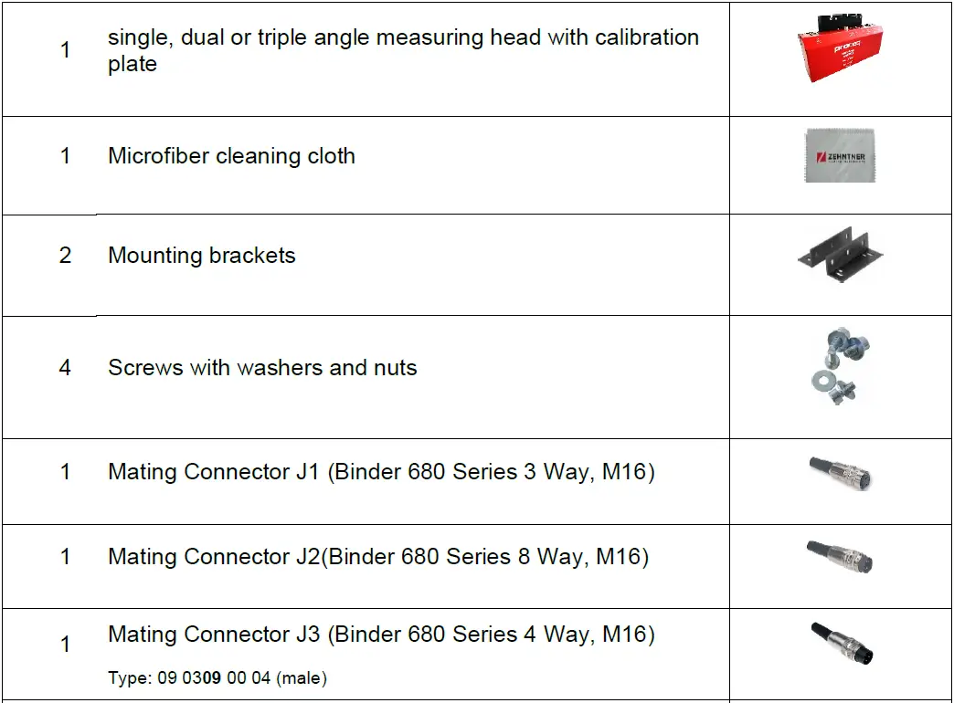
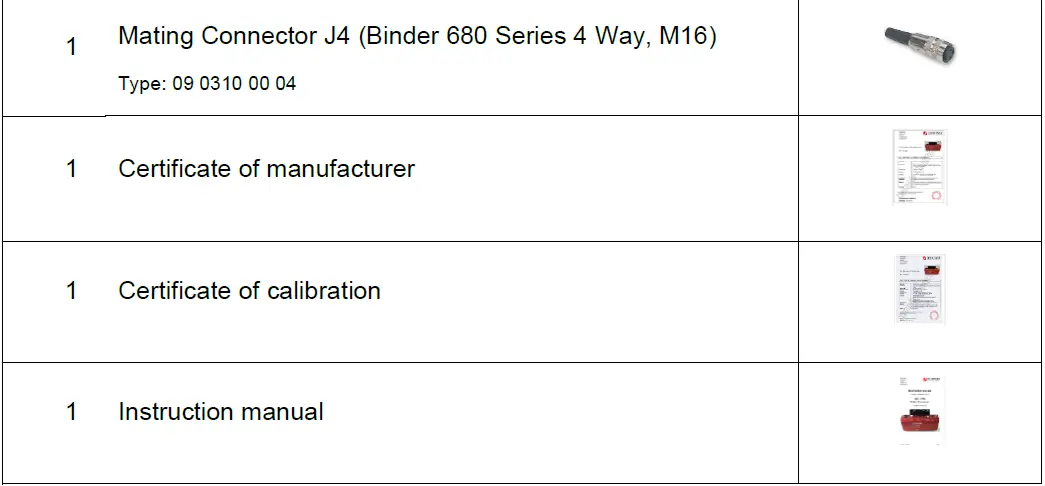
Note: Proceq SA refuses all warranty and liability claims for damages caused by usage of the ZOL 1150 in combination with non-original accessories, or accessories from third-party suppliers.
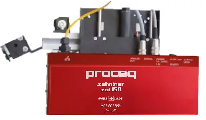
Device Overview
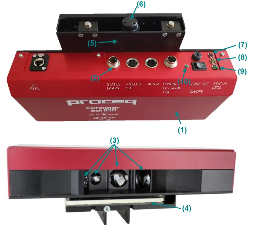
- Measuring head
- Connector panel
- Optical lenses
- Calibration plate
- Z-axis
- Z-axis motor
- Red status LED
- Orange status LED
- Green status LED
- Green power LED
Connection technology
The measuring head can be connected in the following ways:
- Ethernet / TCP/IP/UDP
By using Ethernet connection, the measuring head can be accessed over a web based interface. Over the web interface, it is possible to modify settings on the measuring head. Furthermore all functions of the measuring head software, such as calibration can be accessed. - PLC Signals
The measuring head can be controlled by hardware signals coming from a command unit, for example a PLC. Commands such as calibration can be engaged. - Analog output
The measured values are available as analog output signals. Three analog output modes are possible: 0-10V, 0-20mA and 4-20mA. The modes can be chosen over the web interface.
Measuring head technology
The measuring head is equipped with precision monobloc optics. This optical block assures best precision of the optical apertures and light beams. The illumination unit is a regulated white LED, which produces modulated light. Possible light source instability due to temperature changes or lifetime degradation of the LED is compensated with a special compensation circuit that has been developed for this device.
The sensor is V (![]() ) adapted (adapted to the spectral sensitivity of the human eye). The gloss measuring circuit compensates any offset produced by stray light or other influences.
) adapted (adapted to the spectral sensitivity of the human eye). The gloss measuring circuit compensates any offset produced by stray light or other influences.
This leads to extremely stable and precise measuring results.
Setting up
Connections and Signals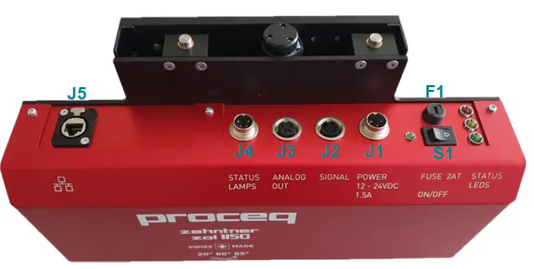
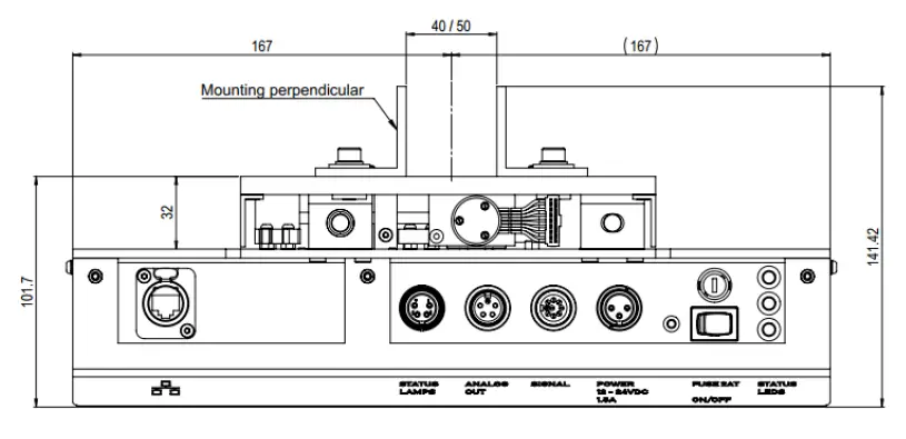
Connector Overview
| Connector | Description | Type | Recommended mating connector |
| J1 | POWER 24 VDC 1.5A | Binder 680 Series 3 Way, M16 09 0307 00 03 | Binder 680 Series 3 Way, M16 09 0306 00 03 |
| J2 | SIGNAL Used for interfacing with hardware commands. | Binder 680 Series 8 Way, M16 09 0474 00 08 | Binder 680 Series 8 Way, M16 09 0571 02 08 or 09 0571 00 08 |
| J3 | ANALOG OUT Analog output of measured gloss value. | Binder 680 Series 4 Way, M16 09 0312 00 04 | Binder 680 Series 4 Way, M16 09 0309 00 04 |
| J4 | STATUS LAMPS Switched outputs for status lights | Binder 680 Series 4 Way, M16 09 0311 00 04 | Binder 680 Series 4 Way, M16 09 0310 00 04 |
| J5 | RJ45 Jack Terminal for Ethernet connection | Neutrik NE8FDX-P6-B | NE8MC or NE8MX |
| Switch & Fuse | Description | Type | Recommended mating connector |
| S1 | Main switch | – | – |
| F1 | Main fuse | – | – |
Connector pin assignment and signals
- J1 – POWER Connector
Connector Pin Name Description J1 1 Power negative (ground)
Negative power potential, usually ground J1 2 Power positive Positive power potential, 24 VDC, ±10%, Power consumption: · Measuring max 10 W
· For movement of the Z-axis max 18 W polarity protected
J1 3 Housing Connected to the housing of the instrument. Usually, this pin needs to be connected to power negative (ground). In some cases it might be necessary to connect this pin to a separate earth potential.
J1 Shield Connected to the housing of the instrument. - J2 – SIGNAL Connector
Connector Pin Name Description J2 1 CALIBRATE (Isolated Input)
Active Low Input Active: “0” (≤0.8V) or tie to COMMON
(Signal Ground)
Not active “1” (≥1.4V) or leave unconnected Impedance 20kΩ, max. 30V
J2 2 MOVE TO MEASURING POSITION (Isolated Input)
Active Low Input Active: “0” (≤0.8V) or tie to COMMON
(Signal Ground)
Not active: “1” (≥1.4V) or leave unconnected Impedance 20kΩ, max. 30V
When active, measuring head will move to the calibration position, but will not
calibrate.
J2 3 MOVE TO CALIBRATIO N POSITION (Isolated Input)
Active Low Input Active: “0” (<0.8V) or tie to COMMON
(Signal Ground)
Not active: “1” (≥1.4V) ) or leave unconnected
Impedance 20kΩ, max. 30V
When active, measuring head will move to the measuring position.
J2 4 RESET (Device) (Isolated Input)
Active Low Input Active: “0” (≤0.8V) or tie to COMMON
(Signal Ground)
Not active: “1” (≥1.4V) or leave unconnected
Impedance 160kΩ, max. 30V
J2 5 GROSS VALUE ALARM (Isolated
Output)
Active Low Output (Type: Open Collector -> current-sourcing) Protected (Short Circuit, ESD) max. 20mA (Load), max 30V
J2 6, 7 Not connected
J2 8 COMMON Ground Signal
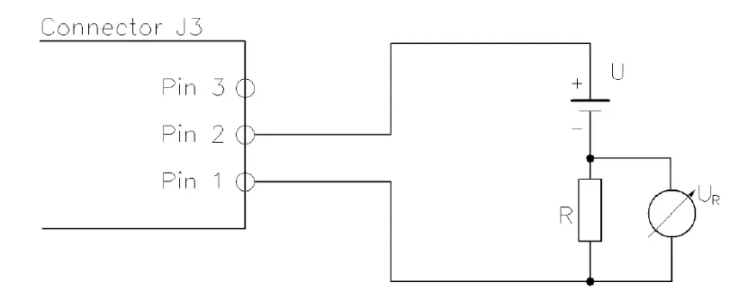
Isolated from Power Ground J2 Shield Connected to the housing of the instrument - J3 – ANALOG OUT Connector
Connector Pin Name Description J3 1 COMMON-Ground (Analog output) Isolated from Power Ground J3 2 Current-Loop Output (Isolated Output) Current range: 0-20mA or 4-20mA Protected (Short Circuit, ESD) Supply Voltage for current loop U = 5 to 30 V.
J3 3 Voltage Output (Isolated Output) Voltage range: 0-10V Protected (Short Circuit, ESD) Max. 65mA
J3 Shield Connected to the housing of the instrument. Connection diagram of the analog output:

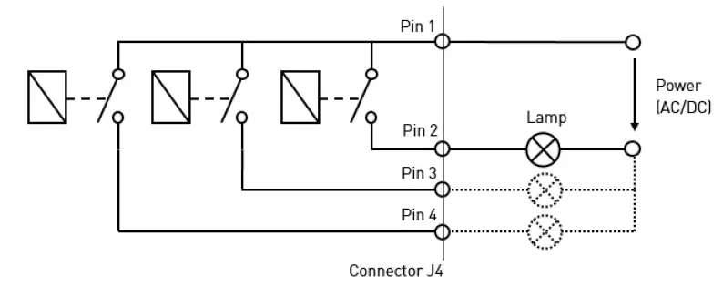
- J4 – STATUS LAMPS Connector
Connector Pin Name Description J4 1 COMMON (Power) Max. switching voltage 30 VDC Max. switching current: 2.5A
J4 2 System lamp (green)
Active closed contactor which indicates that the system is running. It has always the same status as the green status LED (9) on the measuring head. J3 3 Action lamp (yellow) Active closed contactor which indicates that action is going on (such as motor moving) or that a user interaction is required. It has always the same status as the orange status LED (8) on the measuring head. J4 4 Error lamp (red)
Active closed contactor which indicates an error. It has always the same status as the red status LED (7) on the measuring head. J4 Shield Connected to the housing of the instrument. Connection diagram of the lamps:

Mounting of the device
The ZOL1150 allows various mounting configurations, which allows a flexible use of the device.
In an inline production setting the device is often mounted on a traversal unit. (not within the scope of delivery).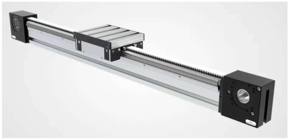
Mounting Configurations:
Vertical to the material to be measured. 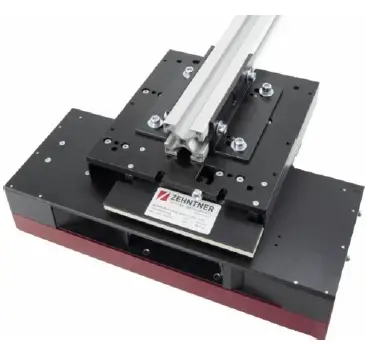 Horizontal to the material to be measured, version 1.
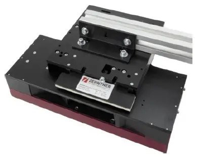
Horizontal to the material to be measured, version 2. 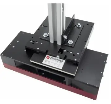 The measurement direction can also be either in the moving direction of the material or perpendicular to it.
In moving direction 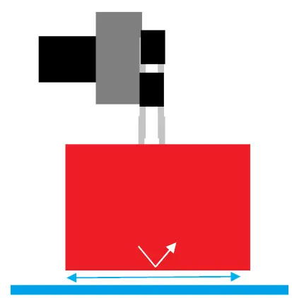
Perpendicular to moving direction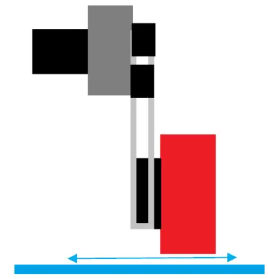
It’s important to install the device with the respective measurement distance. In order to guarantee a stable measurement distance in a moving setup, mounting a transmission roll before and after the device is recommended. This will reduce vibrations of the material and help to achieve stable results. 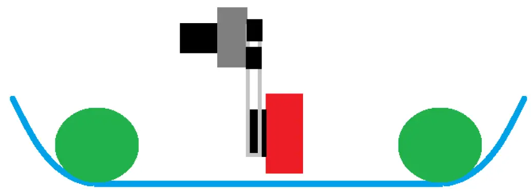
- Installation
- Only install the measuring head if it is in the measuring position. Otherwise you will risk a crash when the measuring head moves out to the measuring position.
- The distance between the material and the measuring head housing should be adjusted to respective measurement distance. You will need to make sure that the measuring head is precisely parallel to the material.
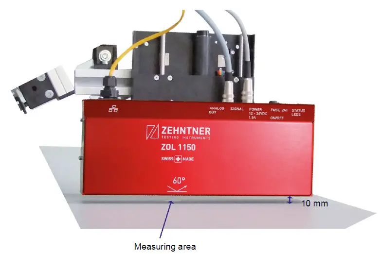
- Measuring area
The indication arrow printed on the device indicates the center of the measuring range and the measuring direction. The dimensional drawings show the exact positioning of the measuring area.
 The dimensional drawings show the exact positioning of the measuring area.
Dimensional drawings
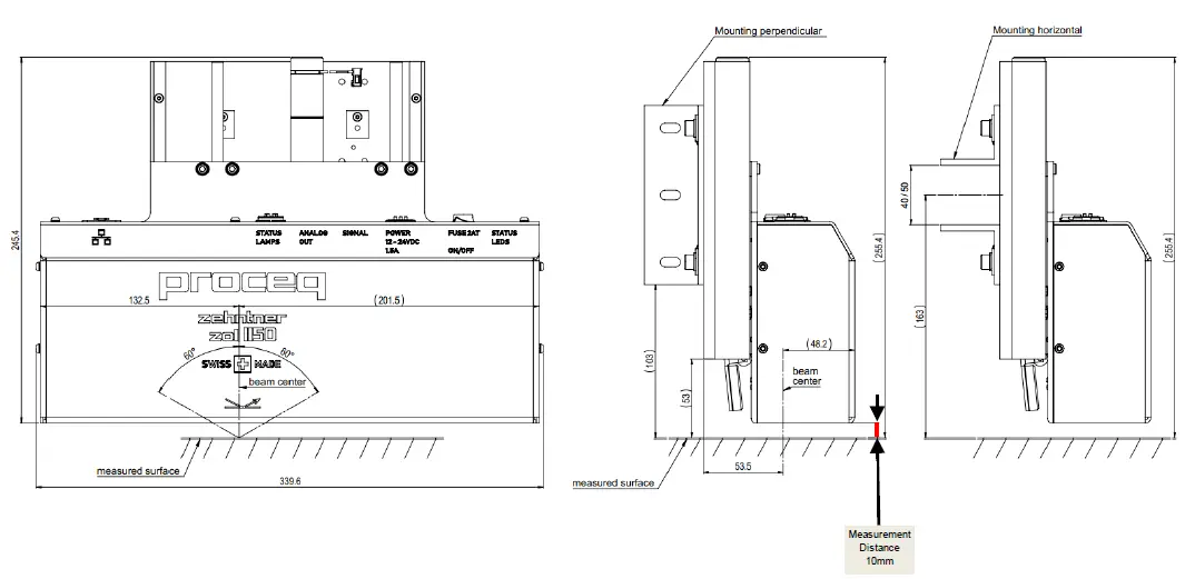
- ZOL1150.26 – Dual Angle
Measurement Position Calibration Position
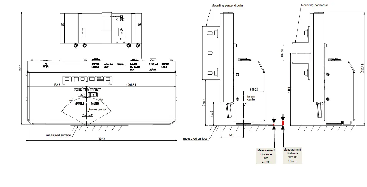
- ZOL1150.268 – Triple Angle
Measurement Position Calibration Position
- Top View

 Calibration Position
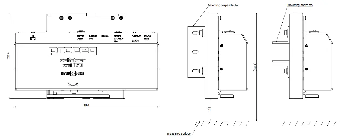
 Calibration Position
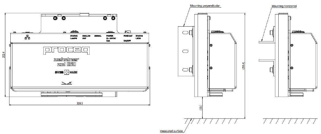
Starting up
The device is switched on by the main switch S1. After switching on, the power LED (10) will light up and the device will take up to 80 seconds until it has completely booted up. Towards the end of this procedure, the orange status LED (8) starts to blink once per second and then extinguishes. Finally, the green status LED (9) lights up and the device is ready by turning automatically into the measuring mode. It is now providing measured data on the Ethernet port and on the analog output.
If the Z-axis (5) is not in measuring position, the orange status LED (8) will keeps glowing even after the booting process.
The device can simply be shut off with the main switch S1.
Z-Axis Control
The measuring head has an integrated Z-axis (5). It is used for calibration and for moving the measuring head away from the material in case more distance between the measuring head and the material to be measured is needed.
The position of the measuring head is controlled with a motor (6) and has two positions:
| Calibration position: In the calibration position, the measuring head (1) is away from the material. The calibration tile (4) is located under the measuring head (1). | Measuring position: In the measuring position, the measuring head (1) is close to the material. The measuring head is ready to measure. |
 |  |
A Z-axis movement is caused by two operations:
- Calibration
When a calibration is initiated, the measuring head will move from the measuring position to the calibration position. After calibration it will move back to measuring position. - Position control
The position of the Z-axis (5) can also be controlled manually with the position control function. This function is needed e.g. if you need to move away from the material because of maintenance work in the production line.
Position control can be accessed either by the web interface or the Z-AXIS POSITION input on connector J2 pin 3.
The Z-axis (5) uses a special positioning procedure in order to increase positioning precision.
When moving up, the procedure is as follows:
- a) move up fast
- b) move a little bit down
- c) move back up slowly in order to find the precise position
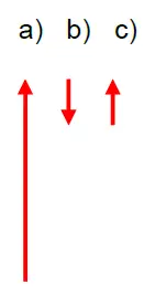
When moving down, the procedure is the same but in the opposite way.
If the measuring head is moved to the calibration position with the external command on connector J2 pin 2 and this signal is kept active, the measuring head remains in the calibration position after a calibration has been started.
The following table shows all input combinations (J2, pins 1-3 and the respective result.
| Input combination (on connector J2) | Result | ||
| J2/Pin 3 „move to calibration position “ | J2/Pin 2 „move to measuring position “ | J2/Pin 1 „calibrate “ | |
| false | false | false | Motor stop |
| false | false | true | Calibrate and afterwards move to position “measure”. |
| false | true | false | Move to position “measure”.^ |
| false | true | true | Calibrate and afterwards move to position “measure”. |
| true | false | false | Move to position “calibrate”, but without calibration. |
| true | false | true | Calibrate and afterwards stay in calibration position. |
| true | true | false | Move to position “calibrate”, but without calibration. |
| true | true | true | Calibrate and afterwards stay in calibration position. |
Note:Please note that the logical inputs on the connector J2 are active low (true = 0 Volts)
Web interface
- Getting started
The web interface allows controlling the device over a computer that is connected to the measuring head over Ethernet. To view the web interface, please open a web browser and enter the following address with the IP Address of the device: HTTP://[IP Address]:8002/gui
Example with the default IP Address: http://192.168.1.10:8002/gui - IP address
The default IP address of the instrument is 192.168.1.10.
The IP address can be configured by changing a file on the instrument. The file can be accessed using an FTP client. When you have an unknown IP address you can retrieve the IP address over the MAC address of the network adapter. You will find the MAC address on the serial number label on the device.
In order to change the IP address, please carry out the following steps:- Connect a computer to the device using an FTP client (ftp://192.168.1.10)
- Download the file ni-rt.ini to your computer
- Open the file with a text editor
- Change the IP address by editing the line “IP Address=”192.168.1.10”
- Save the file on your computer
- Upload the file to the device with FTP
- Restart the device
- Main Page
The main page of the web interface shows the following:

UI Element Name Description W1 System lamp Indicates that the system is running. This indicator has always the same status as the green status LED (9) on the measuring head.
W2 action lamp Indicates that action is going on (such as motor moving) or that a user interaction is required. This indicator has always the same status as the orange status LED (8) on the measuring head.
W3 Error lamp Indicates an error. This indicator has always the same status as the red status LED (7) on the measuring head. W4 Gloss value alarm Indicates that the gloss value is out of range. This indicator has the same status as the output “GLOSS VALUE ALARM” on the connector J2 Pin 5 of the measuring head. The gloss range can be set in the Settings page of the web interface tool. W5 Gloss value Displays the actual gloss value. This value is updated once a second. W6 Maximal value Displays the maximal value of the 100 single measurements that were used to calculate the gloss value. W7 Minimal value Displays the minimum value of the 100 single measurements that were used to calculate the gloss value. W8 Standard deviation Displays the standard deviation of the 100 single measurements that were used to calculate the gloss value. W9 Time Indicates the time of the measurement. W10 Gloss value graph The graph shows the gloss value (y axis) over time (x axis). W11 Graph settings These adjustment tools can be used to modify the display mode of the graph. W12 Geometry selection Selection of the active geometry. - Calibrate page


UI Element Name Description W13 Calibration value The calibration value used for calibration. It has to be identical with the value written on the calibration plate.
W14 Enable geometry for calibration Enables the geometry for the calibration process. W15 Calibrate button When this button is pressed, the calibration process will be launched. W16 External calibration command Indicates the logical status of the external “calibration” command. The external calibration command can be wired to the measuring head on connector J2 pin 1. W17 External move to calibration position command Indicates the logical state of the external “move to calibration position” command. The external “move to calibration position” command can be wired to the measuring head on connector J2 pin 2.
W18 External move to measuring position command Indicates the logical status of the external “move to measuring position” command. The external “move to measuring position” command can be wired to the measuring head on connector J2 pin 3. W19 Position indicator Indicates the position of the Z-axis of the measuring head. When the indicator is green the measuring head is either in calibration or in measuring position. When the indicator is orange, the measuring position is not exactly known or the head is moving between the two positions.
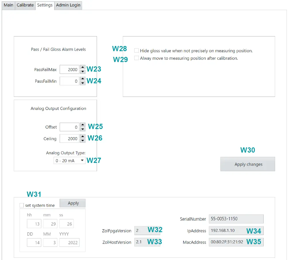
W20 Move to calibration position button When this button is pressed, the measuring head will move to the calibration position. W21 Move to measuring position button When this button is pressed, the measuring head will move to the measuring position. W22 Stop motor button When this button is pressed, the measuring head movement on the Z-axis will stop immediately. - Settings page


UI Element Name Description W23 Pass / Fail maximum value With this Pass/Fail function a maximum gloss value for the measurements can be specified. Whenever the measured gloss value exceeds the maximum level, the gloss value alarm will be active. The gloss value alarm is indicated on the main page as well as on the logical output on connector J2 pin 5 on the measuring head.
W24 Pass / Fail minimum value With this Pass/Fail function a minimum gloss value for the measurements can be specified. Whenever the measured gloss value is lower than the minimum level, the gloss value alarm will be active. The gloss value alarm is indicated on the main page as well as on the logical output on connector J2 pin 5 on the measuring head.
W25 Analog Output Offset Allows having an offset of gloss units on the analog output. The default value is 0. When you give an Offset of e.g. 10, the analog output will stay
UI Element Name Description at 0V (in 0-10V mode) or 4 mA (in 4-20mA mode) until 10 gloss units have been reached.
W26 Analog Output Ceiling Sets the gloss value when the analog output is at 100%. The default value is 100. This means when 100 gloss units are measured, the analog output will give out 10V (in 0-10V mode) or 20 mA (in 4-20mA mode).
W27 Analog Output Type Three analog output modes are available: 0-10V voltage mode 0-20 mA current loop mode 4-20 mA current loop mode
W28 Hide gloss value when not precisely on measuring position When this function is enabled, the gloss value on the graph will only be updated while the measuring head is precisely on the measuring position. In all other cases, the measured value will not be updated. W29 Always move to measuring position after calibration When this function is enabled, the measuring head moves to the measuring position after the calibration process. W30 Apply changes button When some settings have been changed, click on this button in order to save the changes. Otherwise the changes will be lost the next time the measuring head is booted up. W31 Time and Date Block Indicates the current time and date of the measuring head. Time and date can be changed by entries into this block. W32 FPGA Version Indicates the version of the FPGA. W33 Host-Version Indicates the version of the host system. W34 IP-Address Indicates the IP address of the measuring head network adapter W35 MAC-Address Indicates the MAC address of the measuring head network adapter
Measurements
General
After switching on the device, it takes about 80 Seconds until it has completely booted up and is ready to measure by turning automatically into the measuring mode. It is now providing measured data on the Ethernet port and on the analog output.
When the device has not been used for a period of time, it is recommended to let the device run for about 10 minutes in order to heat it up. Afterwards a calibration should be performed to make sure the measured value is correct, and the Z-axis is in the right position.
Pass/Fail
With the pass/fail function a valid gloss range for the measurements can be specified. Whenever the measured gloss value exceeds the maximum level or falls below the minimum, the gloss value alarm will activate. This allows for supervising whether the measured gloss value is in its defined range.
The gloss value alarm is visualized in the web interface. It is also available as a digital output on connector J2 Pin 5.
The pass/fail levels can be set over the web interface.
Calibration
- Calibration procedure
The measuring head is equipped with an automatic calibration procedure. As soon as a calibration command is sent to the measuring head, it moves along the Z-axis until it is on the calibration plate. Then the calibration is carried out and the measuring head moves back to the measuring position automatically.
The calibration can be initiated in two ways, either over the web panel or a digital I/O.
When using the digital I/O, pin 1 of the connector J2 has to be touched to COMMON for about 1 second. - Calibration plate
The calibration standard is mounted on a swiveling plate. When the measuring head is in measuring position, the calibration plate is located at the side of the measuring head.
As soon as the measuring head is moved into calibration position, the calibration plate will swivel under the measuring head. It is then automatically positioned correctly for the calibration to be performed (usually automatically).
The calibration standard has been measured by Zehntner. In order to prevent wrong calibration values, protect the calibration standard from dust, moisture and other environmental factors.- After the expiry date a factory calibration of the ZOL 1150 and its corresponding calibration plate is required. Contact either Proceq or your authorized Proceq agent.
- The factory calibration is valid for two years.
- The calibration plate delivered with the ZOL 1150 is valid only for the delivered instrument. The serial number of the measuring head together with the corresponding calibration plate are shown on the certificate of calibration.
- Cleaning the calibration plate
Should the calibration plate be soiled or covered by dust, it can be cleaned carefully using window cleaner and a soft tissue such as the supplied microfiber cleaning cloth. The following steps explain the cleaning procedure:- Move the measuring head into the calibration position. This can be done over the web interface with the digital command Z-AXIS POSITION on connector J2 pin 3.
- Fold down the calibration plate carefully.
- Clean the calibration standard with a soft tissue such as the supplied microfiber cleaning cloth.
- Bring the calibration plate back to its default position.
- Move the measuring head back to the measuring position.
NOte: A damaged or polluted calibration plate may cause incorrect calibration and therefore incorrect measuring results.
- Replacing the calibration plate
The calibration plate can be removed for replacement or new certification.
Follow these steps to remove the calibration plate from the measuring head:
Make sure the measuring head is in the measuring position.
Loosen and remove the 2 Allen screws on the backside of the measuring head. Carefully remove the calibration plate.
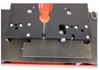 Carefully remove the calibration plate.
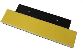
Protocol Specification
Introduction
This section describes the proprietary protocol of the Zehntner ZOL 1150 glossmeter. This protocol allows to control the device and read the measurements with a connected computer.
Protocol
The data protocol of the ZOL 1150 consists of two types of protocols:
Data sentences and commands.
All types of protocols are text based.
The delimiter is the vertical bar character “|” (ASCII code 124).
The terminator is semicolon character “;” (ASCII code 59).
The port for UDP and TCP/IP communication is always 4450.
Data sentences
Data sentences are read only. They are sent out from the measuring head in a
broadcast manner. Typically, sentences are sent over UDP.
As soon as the measuring head has started up completely (may take 30 seconds), it will start measuring gloss and send out data sentences. These sentences contain
information such as measured gloss value and are pushed out by the measuring head
each second (except DSF every 10 ms).
Data sentences always start with a 3-character code, followed by one or more data
strings.
DSM – Data Sentence for Main information
The DSM sentence provides measurement information in a 1 Hz interval.
Format:
DSM|TimeOfMeasure|Angle|GlossValue|MaxGlossValue|MinGlossValue|StdDev|Gloss ValueAlarm|ErrorFlag
| Parameter | Native data type | Example |
| DateTimeOfMeasure | DateTime | 03.05.2013 17:35:05.000 |
| Angle | Double | 85° |
| GlossValue | Double | 83.61 |
| MaxGlossValue | Double | 83.64 |
| MinGlossValue | Double | 83.55 |
| StdDev | Double | 0.01 |
| PassFailAlarm | Bool (1 / 0) | 0 |
| ErrorFlag | Bool (1 / 0) | 0 |
Example of a DSM sentence that has been sent out by the glossmeter:
DSM|03.05.2013 17:35:05.000|85°|83.61|83.64|83.55|0.01|0|0;
DSD – Data Sentence Digital I/O
The DSD sentence represents the state of the boolean inputs/outputs on the device. It is pushed out every second.
Format:
DSD|ExtCalibrateCommand|ExtZAxisPosition0Command|ExtZAxisPosition1Command| ExtReelChange|ExtAlarmOut|ExtSpareOut|ZAxisPosition0|ZAxisPosition1| ZAxisPreciseOnPosition0|ZAxisPreciseOnPosition1|SignalLampGreen| SignalLampOrange|SignalLampRed
| Parameter | Native data type | Input/Output | Remarks |
|
ExtCalibrateCommand |
Bool (0/1) |
Input | These signals represent the levels at the “Signal” connector |
| ExtZAxisPosition0Command | Bool (0/1) | Input | |
| ExtZAxisPosition1Command | Bool (0/1) | Input | |
| ExtReelChange (future use) | Bool (0/1) | Input | |
| ExtAlarmOut | Bool (0/1) | Output | |
| ExtSpareOut (future use) | Bool (0/1) | Output | |
| ZAxisPosition0 | Bool (0/1) | Input | |
| ZAxisPosition1 | Bool (0/1) | Input | |
| ZAxisPreciseOnPosition0 | Bool (0/1) | Input | |
| ZAxisPreciseOnPosition1 | Bool (0/1) | Input | |
| SignalLampGreen | Bool (0/1) | Output | |
| SignalLampOrange | Bool (0/1) | Output | |
| SignalLampRed | Bool (0/1) | Output |
Meaning of Position0 and Position1:
Position 0: Measuring head in calibration position
Position 1: Measuring head in measuring position
Example of a DSD sentence that has been sent out by the glossmeter:
DSD|0|0|0|0|0|0|0|1|0|1|1|0|0;
DSS – Data Sentence State
The DSS sentence gives information whether the device is in measuring or in calibration state.
Format: DSS|State
| Parameter | Native data type |
| State: | “Measuring” or “Calibrating” |
Example of a DSS sentence that has been sent out by the glossmeter:
DSS|Measuring;
DSF – Data Sentence Fast
The DSF sentence is pushed out every 10 milliseconds. It contains only the gloss value of the currently active angle.
Format: DSF|GlossValue
| Parameter | Native data type | Example |
| GlossValue | Double | 83.61 |
Example of a DSF sentence that has been sent out by the glossmeter:
DSF|83.61;
Commands
Commands are used to configure the measuring head and to send commands, such as
“calibrate”.
They are based on a send-receive topology, where the measuring head is always the client. Typically, commands are sent over TCP.
For the commands, the measuring head acts always as a client. It waits for a command from a host (e.g. a PC) and will answer on that command.
For parameter readouts, the received number format is engineering:
e.g. 22.000000+E0 for the number of 22.
CMD – Movement commands
Movement Commands always start with a “CMD”.
| Example of sending a calibration command | |
| Send to measuring head | CMD|Calibrate; |
| Answer from measuring head if command succeeded | OK; |
| Answer from measuring head if command failed. | NOK; |
Available commands:
| Calibrate | Launches the calibration procedure, including moving to the calibration position and back. A CLE string will report the calibration success and parameters |
| MoveToCalibPosition | Moves the measuring head to calibration position (z-axis). When the measuring head has reached the calibration position a CLE string will be sent on the console. |
| MoveToMeasurePosition | Moves the measuring head to measuring position (z-axis). When the measuring head has reached the calibration position a CLE string will be sent on the console. |
| StopMotor | Stops the movement on the z-axis. |
| ClearErrors | Clears all errors in the error buffer. |
| Example of Move to Calibration Position | |
| Send out | CMD|MoveToMeasurePosition; |
|
Answer on success | OK;
Measuring head starts movement CLE|03/04/22 06:09:38 AM: Z – Axis: Move to pos 0; Measuring head reaches position CLE|03/04/22 06:09:38 AM: Z – Axis: Reached pos 0; |
INF – Parameter Info commands
Info Parameters are read only parameters (settings) on the measuring head. They can be asked with an INF command.
| Example of reading an Info Parameter | |
| Send out | INF|ParameterName; |
| Answer on success | OK|ParameterName|Value; |
| Answer on fail | NOK; |
List of Info Parameters
| Info Parameter name | |
| Temperature | Temperature in °C |
| CpuLoad | CPU load in % |
| GeometryCount | Number of available geometries |
| SerialNumber | Serial number |
| MacAddress | Mac address, format: 00:80:41:ae:fd:7e |
| IpAddress | IP address, format: 192.168.110.245 |
| HostName | Host name of the measuring head |
| Error | Gives back one or more errors |
When the errors are read, (INF|Error;), a list of errors will be sent back. An error always consists of an ErrorNumber, ErrorText and NativeErrorNumber.
Here are some example answers of an error list:
| No error | OK|Error; |
| One error | OK|Error|104|Error1Text|65006; |
| Two errors | OK|Error|104|Error1Text|65006|105|Error2Text|0; |
CFG – Parameter configuration commands
The configurable parameters of the measuring head can be changed over the protocol. After changing these parameters, they are automatically saved and are ready to be used.
To read a configurable parameter the command CFG|GET is used.
To set a configurable parameter the command CFG|SET is used.
| Example of reading a configurable parameter | |
| Send | CFG|GET|ParameterName; |
| Answer on success | OK|ParameterName|Value; |
| Answer on fail | NOK; |
| Example of setting a configurable parameter | |
| Send | CFG|SET|ParameterName|Value; |
| Answer on success | OK; |
| Answer on fail | NOK; |
| Parameter Name | Description | Value range | Comment |
| Geometry | Index of the current geometry | 0,1,2 | |
| SerialNumber | Serial number, read only | ||
| DateTime | Date and time | Format: DD.MM.YYYY HH:MM:SS | |
| MotorSpeedFastDuty | Inverted duty cycle for the fast speed of the z-axis motor. Default: 0 | 0..1 | Do not change |
| MotorSpeedSlowDuty | Inverted duty cycle for the slow speed of the z-axis motor. Default: 0.9 | 0..1 | Do not change |
| AnalogOutFrequency | Modulation frequency of the analog output. Default: 10000 | 1..100000 | Do not change |
| AnalogOutCeiling | Gloss value at which the maximal analog value is reached. Default: 100 | 0..10000 | |
| AnalogOutOffset | Offset for the analog output (in Gloss units) Default: 0 | 0..1000 | |
| AnalogOutMode | Mode of the analog output. 0: 0-10 V 1: 0-20 mA 2: 4-20 mA | 0,1,2 | |
| PassFailMin | Lower value for pass / fail | 0..100000 | |
| PassFailMax | Upper value for pass / fail | 0..100000 | |
| G0Name | Name of Geometry 0 | String | |
| G1Name | Name of Geometry 1 | String | |
| G2Name | Name of Geometry 2 | String | |
| G0Channel | Measuring channel of geometry 0 | Always 0 | Do not change |
| G1Channel | Measuring channel of geometry 1 | Always 1 | Do not change |
| G2Channel | Measuring channel of geometry 2 | Always 2 | Do not change |
| G0MaxValue | 0..100000 | ||
| G1MaxValue | 0..100000 | ||
| G2MaxValue | 0..100000 | ||
| G0StandardValue | 1..100000 | ||
| G1StandardValue | 1..100000 | ||
| G2StandardValue | 1..100000 | ||
| G0PrimaryGain | 0..10000 | Do not change | |
| G1PrimaryGain | 0..10000 | Do not change | |
| G2PrimaryGain | 0..10000 | Do not change | |
| G0RmsOffset | 0..10 | Do not change | |
| G1RmsOffset | 0..10 | Do not change | |
| G2RmsOffset | 0..10 | Do not change | |
| G0SecondaryGain | 0..10000 | ||
| G1SecondaryGain | 0..10000 | ||
| G2SecondaryGain | 0..10000 | ||
| G0DoCalibrate | 0 = false > 0 = true | ||
| G1DoCalibrate | 0 = false > 0 = true | ||
| G2DoCalibrate | 0 = false > 0 = true |
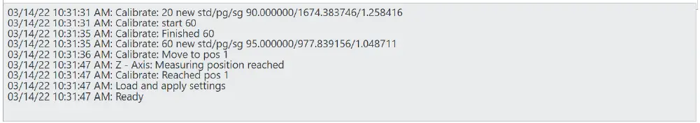
CLE – Console out
The measuring head has a console text, which informs over the activities of the measuring head. The console out can be viewed on the web-frontend of the measuring head and is also stored into a log file.
Furthermore, the console out is pushed to the interface as a CLE. It is only of informative type and may for example be used to display in a console window.
Two examples of console outs:
| CLE|05/28/13 01:50:06 PM: Main Startup; |
| CLE|05/28/13 |
Maintenance and Cleaning
Maintenance and cleaning work that can be carried out by the user
Only the following maintenance and cleaning work shall be carried out by the user:
- Outer cleaning of the device (see chapter 11.2 on page 35).
- Cleaning the calibration plate as described in chapter 11.3 on page 35).
- Replacing the calibration plate (see chapter 9.4 on page 27.
All other maintenance and repair work shall only be carried out by Proceq SA or your authorised Proceq agent otherwise all guarantee and liability claims are void.
Always switch off and unplug the ZOL 1150 before any cleaning and maintenance. The optics housing may not be opened under any circumstances since the measuring geometry would be misaligned. The measuring geometry can only be adjusted by means of special testing equipment in our factory.
The instrument consists of delicate optical and electronic precision parts. Do not drop it and protect it from shocks, moisture and dust.
Cleaning
It is recommended that the instrument is checked and certified by Zehntner every two years.
- Clean the instrument periodically using a soft tissue.
- Wipe the optical lenses (3) on the bottom of the measuring head (1) with the supplied microfiber cleaning cloth or with a lens cleaning tissue.
Fault/Error diagnosis
If the green LED (10) is not glowing, check the following parts:
- Switch (S1) is in position “On”?
- Power is connected (J1) and voltage is in the range 12V to 24V?
- Fuse (F1) is ok and is the right type?
If there are still problems, contact the support of the manufacturer.
Technical Specification
| Geometry | ZOL1150.268: Triple Angle 20°, 60°, 85° ZOL1150.26: Dual Angle 20°, 60° |
| Measuring accuracy | 0 – 199.9 GU: ≈0.2 GU, 0 – 1999 GU: ≈2 GU* |
| Measuring sensor adaption | V(l) |
| Measuring area | 20°: 22 mm x 20 mm (0.87” x 0.79”) 60°: 29 mm x 14 mm (1.14” x 0.55”) 85°: 114 mm x 11 mm (4.49” x 0.43”) |
| Interfaces | Ethernet |
| Analog output | 0-10 V, 0-20 mA or 4-20 mA |
| Light source | LED |
| Power supply | 24 VDC, ±10% |
| Power consumption | max. 18 W |
| Operating Temperature | -10°C to + 50°C (12 °F to 122 °F) |
| Storage Temperature | – 20° C to + 60° C (-4°F to 140°F) |
| Relative Humidity | 10 % to 95 % rF, non condensing |
| Fuse type | 2AT |
| Calibration | traceable to an ISO 17025 accredited laboratory |
| Measuring distance to material | 20°/60°: 10 mm (0.39”) 85°: 2.7 mm (0.11”), 2 mm (0.08”) with slide shoe |
| Calibration position | 20°/60°/85°: 50 mm (1.97”) |
| Tolerance of measuring distance to material | 20°/60°: ± 3 mm (0.12”), 85°: ± 0.5 mm (0.02”) |
| Dimensions measuring head in measuring position | 20°/60°: 339 mm x 142 mm x 243 mm 20°/60°: 13.35” x 5.59” x 9.57” 85°: 339 mm x 142 mm x 250 mm 85°: 13.35“ x 5.59“ x 9.84“ |
| Dimensions measuring head in calibration position | 20°/60°/85°: 339 mm x 142 mm x 203 mm 20°/60°/85°: 13.35” x 5.59” x 7.99” |
| Weight | 20°: 3.9 kg, (8.6 lbs), 20° / 60°: 4 kg (8.8 lbs) |
| Standards | ASTM D823, ASTM D2457, BS 3900-D6, DIN EN ISO 2813, JIS Z 8741 |
*depending on the chosen specifications and under perfectly ideal conditions in a clean environment.
For safety and liability information, please download www.screeningeagle.com/en/legal Subject to change. Copyright © 2022 by Proceq SA, Schwerzenbach. All rights reserved.
PROCEQ EUROPE
Ringstrasse 2
CH-8603 Schwerzenbach Switzerland
+41 43 355 38 00
[email protected]
PROCEQ UK LTD.
Bedford i-lab, Priory Business Park Stannard Way
Bedford MK44 3RZ
United Kingdom
+44 123 483 45 15
[email protected]
PROCEQ USA, INC.
117 Corporation Drive
Aliquippa, PA 15001
U.S.A.
+1 724 512 03 30
[email protected]
PROCEQ ASIA PTE LTD
1 Fusionopolis Way
#20-02 Connexis South Tower 138632 Singapore
+65 6382 3966
[email protected]
PROCEQ RUS LLC
Ul. Optikov 4
korp. 2, lit. A, Office 410
197374 St. Petersburg
Russia
+7 812 448 35 00
[email protected]
PROCEQ MIDDLE EAST
P. O. Box 8365, SAIF Zone,
Sharjah,
United Arab Emirates
+971 6 557 8505
[email protected]
PROCEQ SAO LTD.
Rua Paes Leme, 136, cj 610
Pinheiros, São Paulo
Brasil Cep. 05424-010
+55 11 3083 38 89
[email protected]
PROCEQ CHINA
Unit B, 19th Floor
Five Continent International Mansion, No. 807
Zhao Jia Bang Road
Shanghai 200032
+86 21 631 774 79
[email protected]


