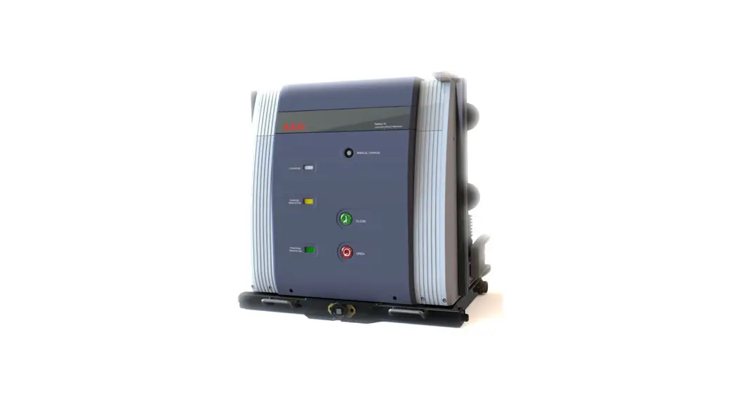
![]() VL-40.5 Vacuum Circuit Breaker
VL-40.5 Vacuum Circuit Breaker
User Manual
VL-40.5 Vacuum Circuit Breaker
Caution!
Please read this manual carefully before installing and using the circuit breaker:
The installation and use of circuit breakers must comply with the requirements of this manual.
Circuit breaker should be used in accordance with the normal indoor environmental conditions.
Any operation and maintenance of the circuit breaker should be carried out by professional trained full-time electrical personnel.
It is forbidden to operate the circuit breaker beyond its rated parameters.
Attention must be paid to any identification of circuit breakers.
It is necessary to ensure the applicability and safety of interlocking conditions and working procedures of circuit breakers.
It is not allowed to carry out maintenance work when the switch cabinet and secondary control circuit are charged.
It must be ensured that the circuit breaker is not impacted by any external force, otherwise the equipment will be damaged.
Any illegal operation of the circuit breaker may damage the equipment and even cause serious accidents.
This manual should be placed in a convenient place.
Professional personnel should be responsible for the safety management of circuit breakers.
Overview
1-1 General:
VL-40.5 vacuum circuit breaker (hereinafter referred to as circuit breaker) is applicable to AC 50Hz and 35kV Power Systems, and can be used as protection and control equipment for industrial and mining enterprises, power plants and substations, and is applicable to frequently operated occasions.
1-2 General provisions:
The circuit breaker complies with the following standards:
| GB/T 1984 | High-voltage alternating-current circuit-breakers |
| IEC 62271-100 | High-voltage switchgear and controlgear – Part 100: Alternating current circuit-breakers |
| IEC 60694 | Common specifications for high-voltage switchgear and controlgear standards |
| DL/T 403 | HV vacuum circuit-breaker for rated voltage 12kV to 40.5kV |
1-3 Normal operating conditions:
| Ambient temperature | |
| Maximum temperature: | + 40ºC |
| Minimum temperature: | – 25ºC |
| Maximum daily average temperature: | + 35ºC |
Ambient humidity
| Daily average relative humidity: | ≤95% |
| Monthly average relative humidity: | ≤90%; |
| Daily average saturated vapor pressure: | ≤2.2×10⁻³ Mpa |
| Monthly average saturated vapor pressure: | ≤1.8×10⁻³ Mpa |
| Earthquake intensity: | No higher than Level 8 |
| Altitude: | ≤ 1000m, conventional products can be used below 1000m above sea level, and high-altitude products need to be noted when ordering. |
Others: no inflammable and explosion hazard, no chemical corrosive gas and no violent vibration.
Note: in case of different use environment or other special requirements, it is necessary to consult with the manufacturer.
Structural principle
2-1 Main structure
The circuit breaker adopts integrated and modular design, and the overall structure is simple and reasonable. It adopts upper and lower settings, with the arc extinguishing chamber part above and the interlocking and operating mechanism part below. Special spring operating mechanism is used, without adjustment, and the action is stable and reliable.
The vacuum arc extinguishing chamber of the three-phase conductive circuit of the circuit breaker is arranged in the closed solid sealing pole column, which not only improves the insulation performance of the phases, but also protects each phase circuit from the influence of the external bad environment, prevents dust and foreign matters from entering the conductive circuit, and reduces the overall size of the circuit breaker.
2-2 Operating mechanism
The operating mechanism of the circuit breaker is a spring energy storage mechanism. There are closing unit, opening unit composed of one or several coils, auxiliary switch, indicating device and other components in the mechanism box; the front is provided with closing and opening button, manual energy storage operation hole, spring energy storage status indicator board and closing and opening indicator board.(Fig.1, 2)
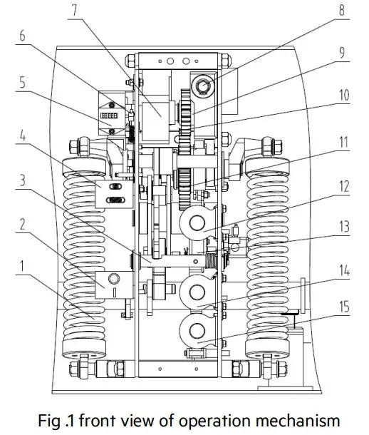 | 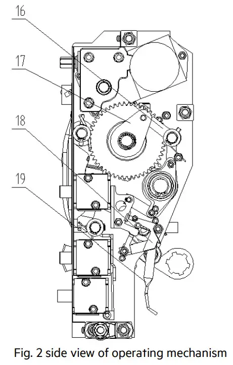 | 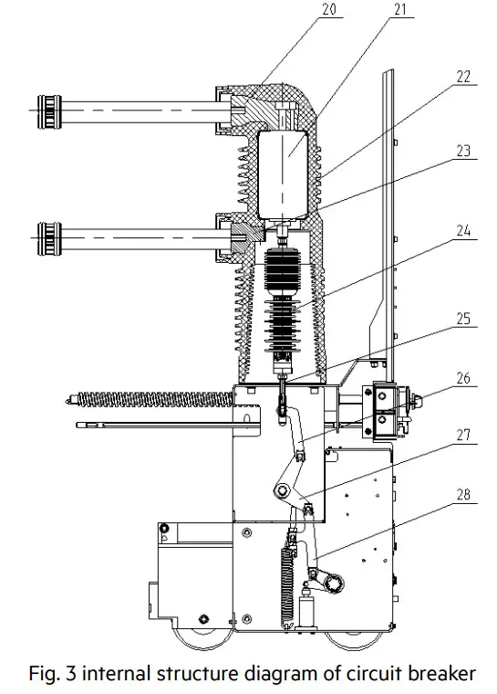 |
| 1 closing spring 2 closing/opening indicator 3 opening latch 4 charging indicator 5 counter 6 micro-switch 7 charging motor 8 manual charging shaft 9 motor output shaft 10 small gear 11 large gear 12 closing coil 13 closing plate 14 opening coil 15 over-current coil/secondary tripping coil | 16 energy storage keeping block 17 energy storage latch 18 closing interlock block 19 handcart interlock block | 20 upper terminal 21 vacuum chamber 22 fixed pole 23 lower terminal 24 insulating pull rod 25 threaded rod 26 connecting plate 27 crank arm 28 connecting plate |
2-2-1 Energy storage
The energy required for closing the circuit breaker is provided by the closing spring. Energy storage can be done either by motor or by hand with energy storage handle.
Energy storage operation: it is carried out by the energy storage motor 7 fixed on the frame or by inserting the energy storage handle into the manual energy storage shaft 8 and shaking it clockwise. The gear system is driven by motor output shaft 9 for electric energy storage, and the gear system is driven by manual energy storage shaft 8 for manual energy storage. When the small gear rotates, it drives the big gear to move together, thus pulling the energy storage spring to store energy. When the energy storage position is reached, the energy storage holding block is supported by the energy storage holding block to separate the clutch and maintain the energy storage position. The energy storage indicator board shows the tension state of the tension spring, and the energy storage is completed. The micro switch cuts off the power supply of the energy storage motor, and the circuit breaker is in the closing ready state.
2-2-2 Closing
During the closing process, whether manually pressing the “closing” button or remote operation to make the closing coil 12 act, the energy storage holding device can be turned away from the energy storage holding block. Under the action of the closing spring force, the cam drives the cam to rotate, and the cam drives the connecting rod mechanism to drive the insulating rod 23 and the moving contact of the arc extinguishing chamber to close.
After the closing action is completed, the opening holding switch and the opening half shaft are kept in the buckle state. At the same time, the energy storage indicator board and auxiliary switch are reset, and the motor power supply circuit is connected. If the external power supply is also connected, it will enter the energy storage state again, and the connecting rod will pull the on / off indicator to indicate the position of “┃”, at the same time, pull the counter to realize counting, and drive the connecting rod to pull the spindle to drive the auxiliary switch to switch.
Note: when the circuit breaker is in the closing state or the closing locking device is selected but the external power supply is not connected, the circuit breaker is in the process of pushing, or the operating handle of the pushing mechanism is not pulled out, the closing operation cannot be performed.
2-2-3 Opening
It can not only press the “opening” button, but also connect the external power supply to make the opening coil or over-current coil act, so that the opening holding switch and the opening half axis are unlocked to realize the opening operation. The energy stored by the contact spring and the opening spring 25 separates the dynamic and static contacts of the arc extinguishing chamber 21. In the later stage of the opening process, the hydraulic buffer absorbs the residual energy and limits the opening position.
Pull the “O” connecting rod to switch off the switch.
2-3 Anti misoperation interlock
The circuit breaker can provide perfect anti misoperation function
- After the closing operation of the circuit breaker is completed, the closing interlocking board 18 rotates against the closing board 13, and it cannot be closed again when the circuit breaker is not opened.
- After closing the circuit breaker, if the closing electric signal is not removed in time, the internal anti tripping controller of the circuit breaker will cut off the closing circuit to prevent multiple reclosing.
- When the handcart type circuit breaker fails to reach the test position or working position, the handcart interlocking board 19 shall buckle the closing board and cut off the closing circuit to prevent the circuit breaker from entering the load area in the closing state.
- After the handcart type circuit breaker is closed in the working position or test position, the trolley will not be able to move if the roller presses the pushing mechanism, so as to prevent pulling out or pushing the load area in the closing state.
- If electrical closing locking is selected, manual closing operation is prevented when the secondary control power supply is not connected.
Technical parameter
3-1 Main technical parameter
| No. | Item | Unit | Value |
| 1 | Rated voltage | kV | 40.5 |
| 2 | Rated power frequency withstand voltage (1 min) | 95/118 | |
| Rated lightning impulse withstand voltage | 185/215 | ||
| 3 | Rated frequency | Hz | 50 |
| 4 | Rated current | A | 630/1250/1600/2000/2500/3150 |
| 5 | Rated short circuit duration | s | 4 |
| 6 | Rated short-circuit breaking current | kA | 25 31.5 |
| 7 | Rated short-time withstand current | 25 31.5 | |
| 8 | Rated short-circuit making current | kA | 63 80 |
| 9 | Rated peak withstand current | kA | 63 80 |
| 10 | Rated operation procedure | O-0.3s-CO-180s-CO | |
| 11 | Opening/closing rating voltage | V | AC: 110/220; DC: 110/220 |
| 12 | Rated voltage of energy storage motor | V | AC: 110/220; DC: 110/220 |
| 13 | Classification | class | E2-M2-C2 |
3-2 Mechanical characteristic parameters
| No. | Item | Unit | Value |
| 1 | Rated voltage | A | 630/1250/1600/2000/2500/3150 |
| 2 | Contact distance | mm | 18±1.0 (Fixed sealing pole) |
| 21±2.0 (Insulating cylinder) | |||
| 3 | Contact travel | mm | 4.0±1.0 |
| 4 | Three-phase closing | ms | ≤2 |
| 5 | Three-phase opening | ms | ≤2 |
| 6 | Closing bounce time | ms | ≤3 |
| 7 | Average opening speed | m/s | 1.3~1.9 |
| 8 | Average closing speed | m/s | 0.5~1.0 |
| 9 | Opening time (rated voltage) | ms | 20~50 |
| 10 | Closing time (rated voltage) | ms | 30~70 |
| 11 | Opening/closing rating voltage | V | AC: 110/220; DC: 110/220 |
| 12 | Rated voltage of energy storage motor | V | AC: 110/220; DC: 110/220 |
| 13 | Main loop resistance | μΩ | 630~1250A≤55; 1600~2000A≤45; above 2500A≤35 |
| 14 | Energy storage time | s | ≤10 |
3-3 Technical parameters of operating mechanism and locking electromagnet
| Rate voltage (V) | Energy storage motor (A) | Closing coil (A) | Opening coil (A) | Lockout electromagnet (mA) |
| DC 110 | 2 | 2.2 | 2.2 | 35 |
| DC 220 | 1 | 1.3 | 1.3 | 20 |
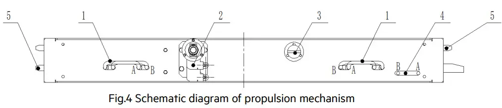
Propulsion mechanism
4-1 Cabinet entry of handcart
Close the valve of the interlocking piece 2 of the pushing mechanism, operate the left and right handles 1 to position B, and push the circuit breaker handcart into the switch cabinet along the guide rail until the pins 5 on both sides correspond to the positioning holes of the switch cabinet. Release the left and right handles to fix the circuit breaker handcart in the switch cabinet. Operate the grounding interlock handle 4 to position a to make it in the insertion position. (if the propulsion mechanism is not equipped with grounding interlock, this step can be skipped).
4-2 Pushed in or pulled out of handcart
Put the circuit breaker in the opening state (manual or electric), open the valve of the interlocking piece 2, and insert the operating handle to make the circuit breaker advance and exit in the cabinet. When the circuit breaker enters the working position or retreats to the test position, the “click” sound of clutch slipping can be heard, and the handcart does not move. At this time, the shaking of the operating handle should be stopped. The advancement and withdrawal of the circuit breaker handcart in the cabinet shall be flexible without obvious jamming. (Note: when the circuit breaker touches the valve mechanism of the cabinet and is almost in place, the propulsion force should be significantly increased, which is normal).
4-3 Closing operation
- Push the handcart into the switch cabinet and operate the left and right handles to position A.
- Open the earthing switch and operate the earthing interlock handle to the position A.
- Press the interlocking piece and turn the main operating shaft clockwise with the handle to push the circuit breaker to the working position in the cabinet.
- Close the interlocking piece, close the circuit breaker and operate.
4-4 Emergency opening
When the switch cabinet is in an emergency, the emergency opening handle 3 rotates counterclockwise to open the circuit breaker.
4-5 Illustration (working position)
- Left and right handles
- Interlocking piece
- Emergency opening handle
- Grounding interlock handle
- Bolt
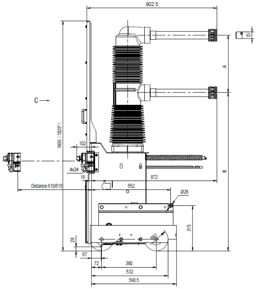
Overall dimensions
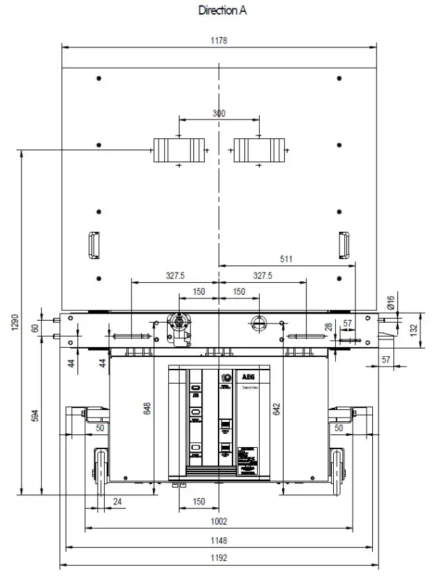
● Fixed sealing pole – 300mm apart
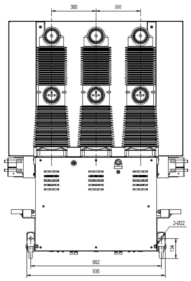 |  |
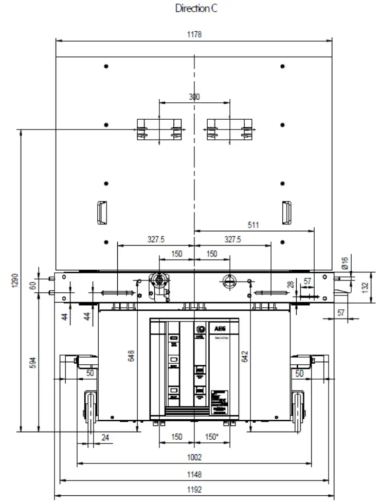 | |
Note:* refers to circuit breaker with specification of 3150A-40k4
| A | B | |
| Specification 1 | 328 | 1061 |
| Specification 2 | 400 | 1100 |
| Specification (spring mechanism) | D | Net weight kg |
| 12504/25-40k4 | 49 | 420 |
| 16004/25–40k4 | 55 | 440 |
| 20004/25-40k4 | 79 | 470 |
| 25004/25-40k4 | 109 | 490 |
| 31504/25-40k4 | 109 | 550 |
● Fixed sealing pole – 440mm apart 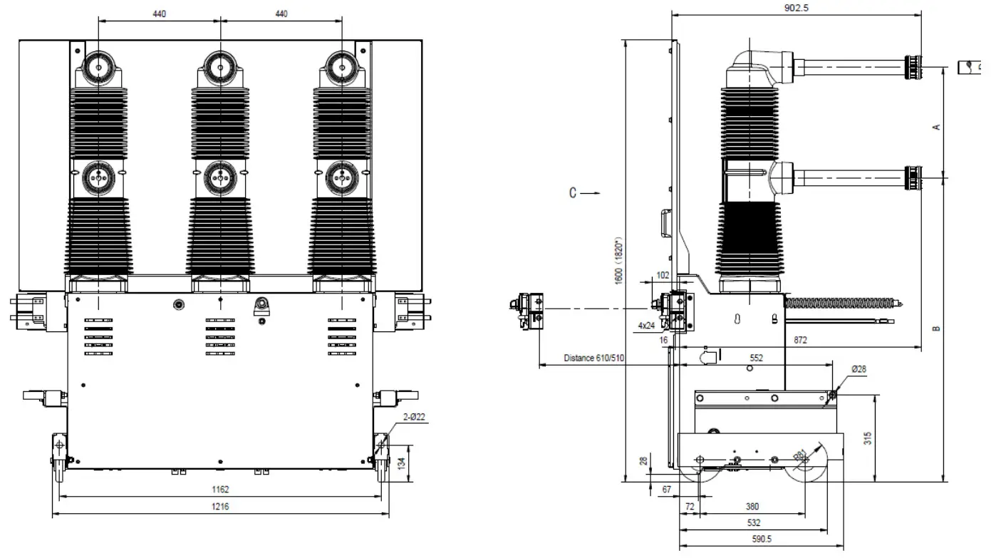
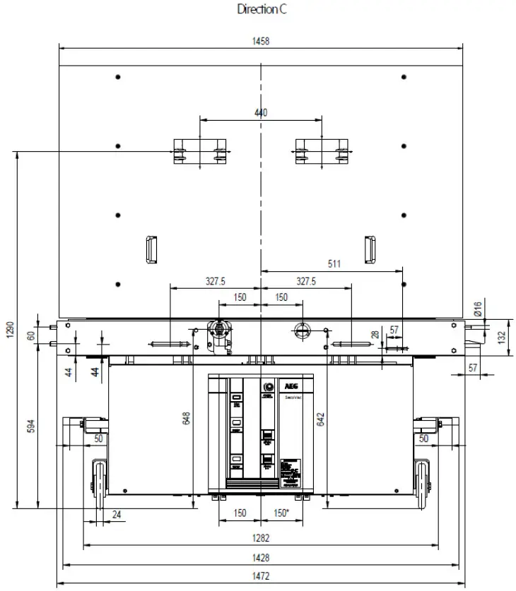 Note:* refers to circuit breaker with specification of 3150A-40kA
| A | B | |
| Specification 1 | 328 | 1061 |
| Specification 2 | 400 | 1100 |
| Specification (spring mechanism) | 0 | Net weight kg |
| 1250A4/25-40kA | 49 | 445 |
| 1600A/25-40kA | 55 | 465 |
| 2000A/25-40kA | 79 | 495 |
| 2500A/25-40kA | 109 | 515 |
| 3150A/25-40kA | 109 | 575 |
● Insulating cylinder- 300mm apart 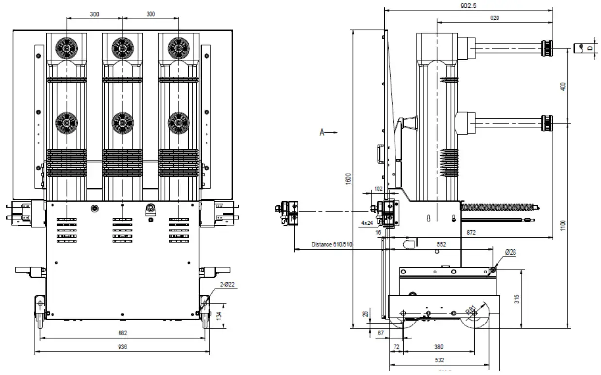
| Specification (spring mechanism) | D | Netweight (kg) |
| 12504/25–31.5k4 | 49 | 420 |
| 16004/25–31.5k4A | 55 | 440 |
| 20004/25-31.5k4 | 79 | 470 |
| 25004/25-31.5k4 | 109 | 490 |
Electrical wiring diagram
● 58 core, with auxiliary contact of propulsion mechanism 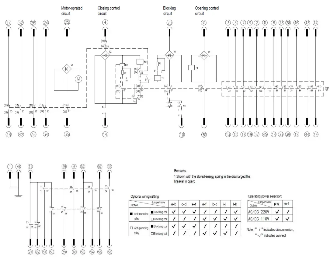
| S9: Limit switch | HQ: Closing coil | V1∼V4: Rectifier |
| S8: Limit switch | TQ: Opening coil | K0: Anti+-pumping relay(Optional) |
| S4: Auxiliary switch for blocking coil | RO∼R1: Resistance | Y1: Blocking coil(Optional) |
| S1∼S3: Energy storage position switch | a∼q: Jumper terminal | S6: Position locking of propulsion mechanism |
| QF: Auxiliary switch | M: Energy-storage motor |
Installation, commissioning and operation
7-1 When the circuit breaker is lifted from the packing box, the hook shall be hung on the lifting position with lifting mark on the circuit breaker. When moving, the upper and lower outlet arms shall not be stressed, and the circuit breaker shall not be subject to large impact and vibration.
7-2 In case of problems in operation, determine the causes according to the table below. If it can’t be solved, please contact the manufacturer. Do not disassemble the circuit breaker by yourself.
| No. | Fault phenomena | Reasons |
| 1 | Failure to closing | 1.The breaker is in the closing position state |
| 2.The handcart does not fully come into operation position or test position | ||
| 3.The closing locking device is employed and the auxiliary supply is unconnected or lower than the specifications | ||
| 4.secondary circuit is incorrect | ||
| 2 | The handcart cannot be pushed in or pulled out | 1 The breaker is in the closing position state |
| 2 The pushing- handle is not fully inserted into the pushing hole. | ||
| 3.The pushing mechanism is not fully placed at the test position, so that the clapper cannot be unlocked with the cabinet body | ||
| 4.The cabinet body earthing interlocking is not released |
7-3 The commissioning and operation work shall be carried out by specially trained personnel who have a detailed understanding of the performance of the circuit breaker. The corresponding protection and prevention measures must be considered in the work.
One of the preconditions for trouble free operation is to use the circuit breaker under normal working conditions according to the corresponding provisions of GB /T 1984 and IEC 60694 standards.
- Check the circuit breaker for damage or any other harmful environmental impact. If there is such a phenomenon, it should be eliminated before power on to restore to normal working conditions.
- Remove dirt, especially on the surface of insulating parts. These may be due to contamination during transportation or storage, which may affect the insulation performance of the product.
- Check the connection status of primary circuit contact, secondary circuit connection and grounding body.
- Manual operation test.
Maintenance
Maintenance must be carried out by AEG personnel or the user’s personnel who are familiar with the equipment and have been trained and qualified. If the maintenance is carried out by the user’s personnel, the user shall be responsible for the consequences of the repair.
8-1 During normal use, the circuit breaker is free of maintenance. Because the circuit breaker has the characteristics of simple structure and durability, it has a long service life. The maintenance work is related to the wear and aging of parts. In order to make the circuit breaker work reliably, the interval time and range of maintenance work needed to be carried out will depend on the influence of working environment, operation times, operation time and short circuit current breaking times and other factors.
8-2 Before maintenance, all auxiliary power supply must be disconnected and there is no danger of power transmission again. The circuit breaker itself is open and the spring is not stored energy. In order to prevent accidents, special care should be taken in the operation mechanism.
8-3 Disassembly and replacement of circuit breaker parts shall be carried out by AEG personnel or corresponding trained personnel, especially during reassembly, necessary adjustment shall be made.
8-4 Maintenance of circuit breaker
a. The operation structure shall be inspected when the circuit breaker has been operated for 5 years (from the day when the new equipment is put into operation) or when the circuit breaker operates for the specified times (5000 times for the circuit breaker with 25kA and below, 4000 times for the circuit breaker with 31.5kA):
- Cut off the energy storage power supply and operate the circuit breaker to close and open once to release energy.
- Check the grease condition of rolling or sliding bearing surface.
- Check the correctness of each component function during electrical and mechanical action.
- Do a comprehensive appearance inspection。
b. The operation structure shall be maintained after 10 years of operation (calculated from the day when the new equipment is put into operation) or the operation times of the circuit breaker (25 kA and less than 10000 times, 31.5 kA circuit breaker for 8000 times, 40kA circuit breaker for 5000 times):
- Cut off the energy storage power supply and operate the circuit breaker to close and open once to release energy.
- Re apply grease to supporting shaft, rolling and sliding bearing.
- Check the correctness of each component function during electrical and mechanical action.
- Check the condition or looseness of fasteners installed at connecting rod, crank arm and supporting rod.
- During maintenance, it is important to check the parts which are subjected to high stress during operation.
In case of replacement of parts, all fasteners shall be replaced.
Comprehensive review of operating mechanism.
8-5 After the circuit breaker has been running for about 5 years or when the operating mechanism is under maintenance, the circuit breaker body should also be inspected. Especially when inspecting the appearance, it is also necessary to check the contamination, damp and corrosion of the equipment surface. Clean the dust on the surface of insulating parts with dry cloth, and then wipe all kinds of dirt with silk cloth with household alkaline cleaning agent or safety cleaner (pay attention to whether the detergent used is applicable to plastic and synthetic rubber materials), and do not use carbon tetrachloride or trichloroethylene to wipe.
The minimum interval of the above inspection work shall be less than 5 years for the switchgear operating in some special use occasions or under harmful environmental conditions (such as in the environment with high pollution and heavy corrosive gas).
Transportation and storage
9-1 When the product is transported, the circuit breaker shall be placed in a closed packing box without energy storage, and a proper amount of desiccant shall be built in. The circuit breaker shall be protected with plastic film to prevent water penetration during loading and unloading and dust intrusion during storage.
9-2 The following tools shall be used to load and unload the packing box
- Crane
- Forklift
- Driving
9-3 Pay attention to the following items during transportation:
- Avoid shocks
- Avoid other destructive mechanical forces
- The lifting appliance should not be hooked on the circuit breaker body or operating mechanism. It should be hooked at the lifting position with lifting mark.
9-4 The circuit breaker shall be stored in the state of opening of operating mechanism and energystorage spring without energy storage.
Basic storage requirements
- The dry and well ventilated storage room shall meet the relevant provisions of GB /T 1984 and IEC 60694.
- The temperature of the storage room shall not be lower than – 15 ° C.
- Do not disassemble or damage the package. Cover with a protective light covering and maintain adequate ventilation.
- Regularly check whether there is condensation phenomenon and other conditions not suitable for storage requirements.
Random documents
a. Product certificate
b. Factory inspection report
c. Packing list
Spare parts
When the user needs, the spare parts can be determined according to the following list, and put orward when ordering, so as to meet the needs.
| Order number (SAP) | Product model |
| 26400056 | Over-current tripping coil (Y8) |
| 36490042 | Over-current control circuit board |
| 26490381 | Closing locking electromagnet (S4) |
| 26490463 | Closing/opening control circuit board (please mention: operation voltage, whether there is anti-tripping, whether there is locking) |
| 26490093 | Closing/opening auxiliary switch (OF) |
| 26490090 | Handcart position auxiliary switch (58, S9) |
| 26490580 | Energy storage position switch (S1, S2, S3) |
| 26490598 | Position locking switch (110V) |
| 26490076 | Position locking switch (220V) |
| 26400055 | Closing/Opening coil (110V) |
| 26400054 | Closing/Opening coil (220V) |
| 26490375 | Breaker energy-saving motor (110V) |
| 26490359 | Breaker energy-saving motor (220V) |
| 26490349 | Pushing handle for withdrawable-type breaker |
| 26490365 | Mechanism energy-saving handle |
| 26490033 | Counter |
| 26490508 | Propelling mechanism handle |
![]() Shanghai AEG Enterprise Development Co., Ltd.
Shanghai AEG Enterprise Development Co., Ltd.  http://weixin.qq.com/r/hnVxaVvESgY1rR8K9yCU


