CMCS FURM99 FusionAir-MRT
Specification
FusionAir-MRT supports WLAN 2.4G/5G (802.11 a / b / g / n), Bluetooth 5.0 and BLE, designed with PCB antenna in SMD form factor, ready to be placed onto a host PCB. The the overall design is compact, low power consumption, transmission distance, anti-interference ability, and low cost, designed specifically for IoT Device, embedded applications, can be widely applied in the field of short-range wireless communications for all occasions. Customers in the use of RF hardware design eliminates the difficulty, and product structure more flexible secondary development of space.
| Specification | Description |
| Product Name | FusionAir-MRT |
| Model No. | FURM99 |
| Package | SMD module |
| Size | 50*40*2 mm |
| Antenna | PCB Antenna |
| CPU | ARM M33 @ 200MHz |
| Modem | WLAN 2.4G/5G (802.11 a / b / g / n) BT5.0 / BLE (Support Bluetooth Low Energy only,not support BR、 EDR) |
| Frequency Range | BLE: 2402~2480MHz, WIFI 2.4G: 2412~2472MHz(CH1~CH13) WIFI 5G: 5180~5320MHz(CH36~CH64)5500~5825MHz (CH100~CH165) |
| RAM | Embedded 512KB |
| Flash | Embedded 4MB |
| SPI Flash Default | 128Mbit |
| Interface | UART/ SPI/I2C/GPIO/ADC/PWM |
| IO Port | 48 |
| Power (Typical Values) | Continuous Transmission: Average˖~71mA Peak˖ 500mA |
| Security | WEP/WPA-PSK/WPA2-PSK |
| Power Supply | Voltage 3.0V ~ 3.6V (Typical 3.3V), Current >50mA |
Application Guide
FusionAir-MRT module comes with pre-program firmware, allowing easy setup and deployment on Fusion wireless network. Communication interface is via standard UART, SPI or I2C interfaces, with a well-defined and simple API.
When powered on, the module will automatically establish a secure connection to Fusion network. No commissioning procedure is needed, and security is hardware-base for robustness.
It offers BLE solution and conforms to the Bluetooth 5 core specification to enhance the throughput and security for various application fields.
- Internet of Things (IoT)
- Secure Payment
- Wearable Devices
- Home and Security
- Health and Fitness
- Beacons
- Industrial and Data Logger
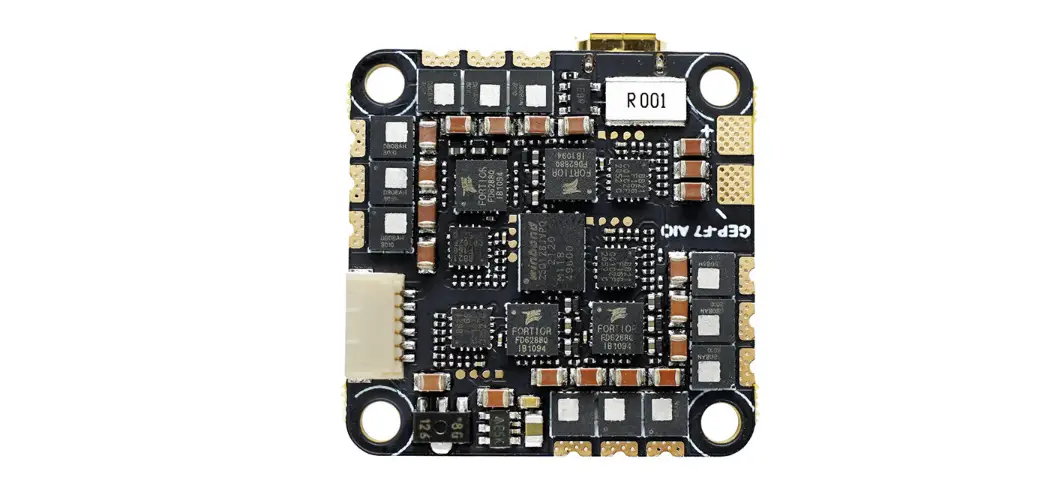
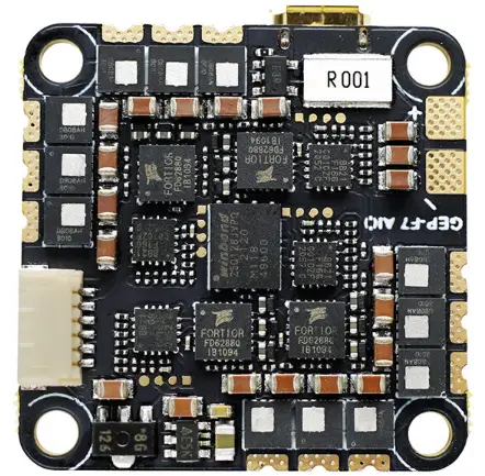
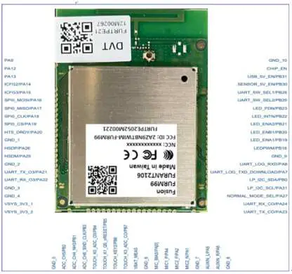
Device Photo
 Size : 54.0mm x 34.0mm x 4.95mm
Install Guide
Antenna Placement
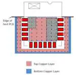
For a Bluetooth wireless product, the antenna placement affects the whole system performance. The antenna requires free space to radiate the RF signals and it cannot be surrounded by the ground plane. Figure 4-1 illustrates a typical example of good and poor antenna placement of the FusionAir-MRT module on the main application board with the ground plane.
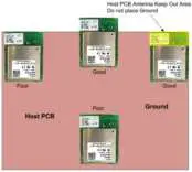 Figure 4-1
Host PCB Mounting Suggestion
The area under the antenna must not contain any top, inner, or bottom copper layer while designing the host PCB. A low-impedance ground plane ensures the best radio performance (best range, low noise). The ground plane can be extended beyond the minimum recommended as required for the host PCB EMC noise reduction. For best range performance, keep all external metal away from the ceramic chip antenna by a minimum of 30 mm.
Block Diagram

Absolute Maximum Ratings
Caution : The specifications in Table 1 define levels at which permanent damage to the device can occur. Function operation is not guaranteed under these conditions.
Operating at absolute maximum conditions for extend periods can adversely affect the long-term reliability of the device.
| Parameter | Min | Max | Unit |
| Storage Temperature | -10 | +40 | ℃ |
| Storage Humidity (40℃) | 20 | 60 | % |
Other conditions
- Do not use or store modules in the corrosive atmosphere, especially where chloride gas, sulfide gas, acid, alkali, salt or the like are contained. Also, avoid exposure to moisture.
- Store the modules where the temperature and relative humidity do not exceed -10 to 40 ℃ and 20 to 60%.
- Assemble the modules within 6 months. Check the soldering ability in case of 6 months over.
Operating Conditions
| Parameter | Min | Typ | Max | Unit |
| Operating Temperature | -20 | – | +55 | ℃ |
| Operating Humidity (40℃) | – | – | 85 | % |
| Supply Voltage | 3.0 | 3.3 | 3.6 | Vdc |
Standard Test Conditions
The test for electrical specification shall be performed under following conditions. Otherwise this following conditions, not guaranteed this performance.
Ambient condition
| Temperature | 25 | ± | 5℃ |
| Humidity | 65 | ± | 5% |
Power supply voltage
| Input Power | Supply Voltage |
| VDD_3.3V | +3.3V ± 0.3V |
Frequency and Antenna Gain
BLE frequency and gain table
| Frequency (MHz) | 2400 | 2410 | 2420 | 2430 | 2440 | 2450 | 2460 | 2470 | 2480 |
| Gain (dBi) | 1.23 | 1.47 | 1.69 | 2.21 | 2.50 | 2.74 | 2.57 | 2.57 | 2.56 |
WIFI 2.4GHz frequency and gain table
| Frequency (MHz) | 2400 | 2410 | 2420 | 2430 | 2440 | 2450 | 2460 | 2470 | 2482 |
| Gain (dBi) | 1.23 | 1.47 | 1.69 | 2.21 | 2.50 | 2.74 | 2.57 | 2.57 | 2.56 |
Wifi 5GHz frequency and gain table
| Frequency (MHz) | 5150 | 5160 | 5170 | 5180 | 5190 | 5200 | 5210 | 5220 | 5230 | 5240 | 5250 | 5260 |
| Gain (dBi) | 1.0436 | 1.2212 | 1.3473 | 1.3473 | 1.4732 | 0.8723 | 1.6918 | 1.6733 | 1.8427 | 2.1454 | 2.4853 | 2.5418 |
| Frequency (MHz) | 5270 | 5280 | 5290 | 5300 | 5310 | 5320 | 5330 | 5340 | 5350 | 5360 | 5370 | 5380 |
| Gain (dBi) | 2.2331 | 2.0122 | 1.7492 | 1.5123 | 1.1153 | 0.3098 | 0.8726 | 0.9197 | 1.0236 | 1.621 | 2.0915 | 2.5657 |
| Frequency (MHz) | 5390 | 5400 | 5410 | 5420 | 5430 | 5440 | 5450 | 5460 | 5470 | 5480 | 5490 | 5500 |
| Gain (dBi) | 2.6225 | 2.6148 | 2.7287 | 2.7172 | 1.97 | 1.8831 | 1.7363 | 2.0831 | 1.5965 | 1.1671 | 2.5396 | 2.1387 |
| Frequency (MHz) | 5510 | 5520 | 5530 | 5540 | 5550 | 5560 | 5570 | 5580 | 5590 | 5600 | 5610 | 5620 |
| Gain (dBi) | 2.425 | 2.4035 | 3.0289 | 2.9099 | 2.9193 | 2.8215 | 2.8567 | 2.7722 | 2.9674 | 2.1827 | 2.8483 | 2.8485 |
| Frequency (MHz) | 5630 | 5640 | 5650 | 5660 | 5670 | 5680 | 5690 | 5700 | 5710 | 5720 | 5730 | 5740 |
| Gain (dBi) | 2.4988 | 2.4926 | 2.1765 | 2.1592 | 1.6529 | 1.7645 | 1.1168 | 1.1114 | 0.8609 | 1.2621 | 0.673 | 0.9443 |
| Frequency (MHz) | 5750 | 5760 | 5770 | 5780 | 5790 | 5800 | 5810 | 5820 | 5830 | 5840 | 5850 | |
| Gain (dBi) | 1.3859 | 1.4287 | 1.8127 | 1.7551 | 2.1022 | 1.9271 | 1.8923 | 1.8612 | 1.8369 | 1.7862 | 1.7356 |
Pin Description
Outline Drawing

Packing Information

Regulatory Notices
FCC
FCC Statements:
This device complies with Part 15 of the FCC Rules. Operation is subject to the following two conditions:
- This device may not cause harmful interference, and
- This device must accept any interference received, including interference that may cause undesired operation of the device.
15.105(b)
This equipment has been tested and found to comply with the limits for a Class B digital device, pursuant to part 15 of the FCC rules. These limits are designed to provide reasonable protection against harmful interference in a residential installation.
This equipment generates, uses and can radiate radio frequency energy and, if not installed and used in accordance with the instructions, may cause harmful interference to radio communications. However, there is no guarantee that interference will not occur in a particular installation. If this equipment does cause harmful interference to radio or television reception, which can be determined by turning the equipment off and on, the user is encouraged to try to correct the interference by one or more of the following measures:
- Reorient or relocate the receiving antenna.
- Increase the separation between the equipment and receiver.
- Connect the equipment into an outlet on a circuit different from that to which the receiver is connected.
- Consult the dealer or an experienced radio/TV technician for help.
15.21
You are cautioned that changes or modifications not expressly approved by the part responsible for compliance could void the user’s authority to operate the equipment.
FCC RF Radiation Exposure Statement:
- This Transmitter must not be co-located or operating in conjunction with any other antenna or transmitter.
- This equipment complies with FCC RF radiation exposure limits set forth for an uncontrolled environment. This equipment should be installed and operated with a minimum distance of 20 centimeters between the radiator and your body.
IMPORTANT NOTE
End Product Labeling
The device is labeled with its own FCC ID and NCC Certification Number. If the FCC ID and NCC Certification Number are not visible when this device is installed inside another device, then the outside of the device into which this device is installed must also display a label referring to the enclosed device.
OEM Responsibilities to comply with FCC and NCC Regulations
The device has been certified for integration into products.
The transmitter device must not be co-located or operating in conjunction with any other antenna or transmitter. As long as the condition above is met, further transmitter testing will not be required. However, the OEM integrator is still responsible for testing their end-product for any additional compliance requirements required with this device installed (for example, digital device emissions, PC peripheral requirements, etc.).


