![]() MC46 Wireless Indoor Outdoor Digital Hygrometer Thermometer
MC46 Wireless Indoor Outdoor Digital Hygrometer Thermometer
User Manual
Display Unit
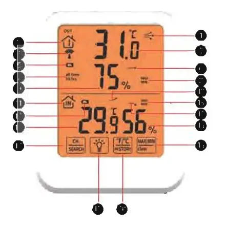
- Arrow icon indicates the direction the temperature is trending
- Channel, there are 3 RF channels selectable
- Current Outdoor Temperature
- Receive signal
- Outdoor Sensor Low Battery Indicator
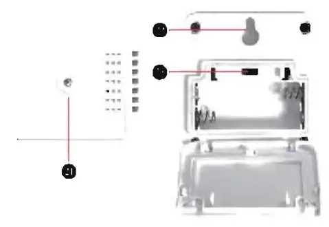
Outdoor Sensor
- Arrow icon indicates the direction the humidity is trending
- The Outdoor Temperature/Humidity of the last 24 hours
- Maximum or Minimum Outdoor Tempera true/Humidity Record
- Current Outdoor Humidity
- Arrow icon indicates the direction the temperature is trending
- Indoor thermometer
- Display Low Battery Indicator
- Maximum or Minimum Indoor Temperature/Humidity Record
- Arrow icon indicates the direction the humidity is trending
- Current Indoor Temperature
- Current Indoor Humidity
- Channel Selection/Search
- MAX/MIN/CLEAR button
- Backlight
- °F/°C/History Button
- Wireless Signal Indicator
- Flashes when data is being sent to the display unit
- Hanging hole
- Slide to set channel l,2 or 3
Product Specifications
Total 4 functional buttons:
CH/SEARCH, BACKLIGHT, F/C/HISTORY, MAX/MIN/CLEAR.
| Displays the indoor&outdoor humidity, temperature, trend and record maximum and minimum humidity/temperature. | |
| Indoor Temperature Range | 14°F-122°F (-10°C -50°C) |
| Outdoor Temperature Range | -40°F-158°F(-40°C-70°0 |
| Temperature Resolution | 0.1°C/°F |
| Temperature Accuracy | ±0.1°C/±1.8°F |
| Humidity Range | 20%-95% |
| Humidity Resolution | 1% |
| Humidity Range Accuracy | ±5%RH (The humidity between 30%-70%) |
| Wireless Range | 032n8eft/m100mpladceependingpty |
| Wireless Frequency | 433 MHz |
| Weight: Main unit | About13lg |
| Weight: Sensor | About 40g |
| Size: Main unit | 1158922mm |
| Size: Sensor | 656519.5mm |
| Power: Display | 2AAA1.5V |
| Power: Sensor | 2AAA15V |
| The Display Unit is capable of displaying the readings from up to 3 outdoor remote sensors to ensure you can monitor multiple locations at the same time such as your bedroom, baby’s room, and your outdoor temp. (There is l remote sensor in the package, extra sensors are sold separately). | |
| Remarks: The outdoor sensor starts reading the exact value and transmitting the signal after 30 minutes. | |
Product Back
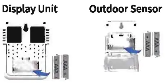
- Open the battery compartment cover.
- Insert 2xAAA batteries into the battery compartment, as shown. Follow the polarity (+/-) diagram in the battery compartment.
- Replace the battery cover.
Tum on the Backlight
Press ![]() once to turn on the light and press
once to turn on the light and press ![]() again to turn off the light. It will be auto-off within 10 seconds without any operation.
again to turn off the light. It will be auto-off within 10 seconds without any operation.
Select Degrees Fahrenheit or Celsius
To select between degrees Fahrenheit (°F) or Celsius (°C) temperature units, press the ![]() once.
once.
Select Channel and SYNC
Press ![]() once to display the temperature and humidity readings from up to 3 outdoor remote sensors.
once to display the temperature and humidity readings from up to 3 outdoor remote sensors.
Press and hold ![]() for 3 seconds to re-synchro size or repair the units. It may take a few minutes for synchronization to complete.
for 3 seconds to re-synchro size or repair the units. It may take a few minutes for synchronization to complete.
To Check All Time/24 HRs History Data
Press ![]() once, in MAX/MIN mode, then press and hold the
once, in MAX/MIN mode, then press and hold the ![]() button for 3 seconds to view the past (all times) or past 24 hours of temperature/humidity.
button for 3 seconds to view the past (all times) or past 24 hours of temperature/humidity.
Using the MAX/MIN Records
MAX MIN Records reflect the minimum and the maximum temperature recorded since the unit was powered on, since the batteries were changed or since it was ma nu ally reset (whichever was most recent).
To view the MAX record, press the ![]() once, the MAX icon appears on the display. To view the MIN record, press the
once, the MAX icon appears on the display. To view the MIN record, press the ![]() once, the MIN icon appears on the display.
once, the MIN icon appears on the display.
To reset the MAX/MIN records, press and hold the ![]() for 3 seconds. Dashes will display to confirm all values have been cleared.
for 3 seconds. Dashes will display to confirm all values have been cleared.
Placement for Maximum Accuracy
Sensors are sensitive to surrounding environmental conditions. Proper placement of both the display unit and outdoor sensor are critical to the accuracy and performance of this product Sensor must be placed outside to observe outdoor conditions. The sensor is rain-proof and is designed for general outdoor use, however, to extend its life place the sensor in an area protected from direct weather elements. (Warning: Sensor must be vertical placement.) Hang the sensor using the integrated hang holes or hanger, or by using string (not included) to hang it from a suitable location, like a well-covered tree branch. The best location is 4to 8 feet, above the ground with permanent shade and plenty of fresh air to circulate around the sensor.
No Outdoor Sensor Reception
Replace the display unit and/or the outdoor sensor. The units must be within 328ft/100m of each other. Make sure both units are placed at least3 feet (9m) away from electronics that may interfere with the wireless communication (such as TVs, microwaves, computers, etc.).
outdoor temperature is Flashing or Showing Dashes
Bring both the sensor and display unit indoors and remove at least one battery from each. Reinstall the battery in the outdoor sensor or display unit.
Let the unit sit within a couple of feet of each other for about 20 minutes to gain a strong connection.
Inaccurate Temperature
Make sure both the display unit and sensor are placed out of direct sunlight and away from any heat sources or vents.
Care Maintenance
Clean with a soft, damp cloth. Do not use caustic cleaners or abrasives. Keep away from dust, dirt, and moisture. Clean ventilation ports regularly with a gentle puff of air.
FCC Statement
This equipment has been tested and found to comply with the limits for a Class B digital device, pursuant to Part 15 of the FCC Rules. These limits are designed to provide reasonable protection against harmful interference in a residential installation. This equipment generates uses and can radiate radio frequency energy and, if not installed and used in accordance with the instructions, may cause harmful interference to radio communications. However, there is no guarantee that interference will not occur in a particular installation. If this equipment does cause harmful interference to radio or television reception, which can be determined by turning the equipment off and on, the user is encouraged to try to correct the interference by one or more of the following measures:
- Reorient or relocate the receiving antenna.
- Increase the separation between the equipment and receiver.
- Connect the equipment into an outlet on a circuit different from that to which the receiver is connected.
- Consult the dealer or an experienced radio/TV technician for help.
This device complies with part 15 of the FCC Rules. Operation is subject to the following two conditions: (1) This device may not cause harmful interference, and (2) this device must accept any interference received, including interference that may cause undesired operation.
Changes or modifications not expressly approved by the party responsible for compliance could void the user’s authority to operate the equipment.


