MOKO MKL110BC Geolocation Module
Instruction
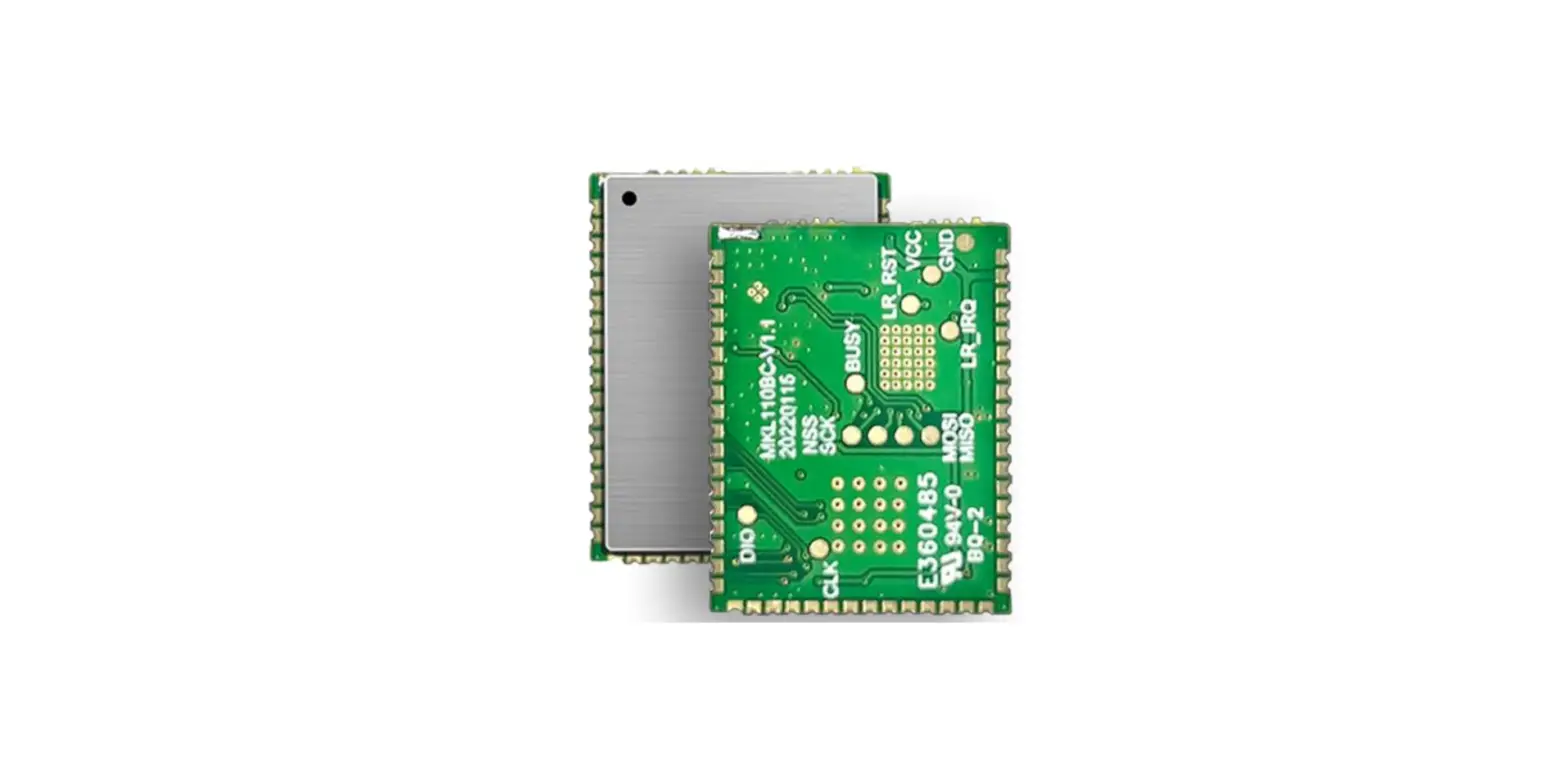
Product Introduction
MKL110BC is a fusion positioning module based on LoRaWAN communication technology. The hardware mainly integrates Semtech’s LR1110 Edge chip and Nordic’s Nrf series Bluetooth chip, which can provide a variety of positioning technologies including Bluetooth positioning, LP-GPS, and WIFI positioning, as well as low power consumption, long-range communication, and high anti-interference characteristics.
It is an ideal platform for developing various Indoor/outdoor tracking product solutions, which can help users reduce development time and development costs.
Features and Benefits
- Cost-effective, ultra-low power, and small size
- Multi-location technology (WIFI Only RX+Bluetooth+LP GPS)
- GNSS (GPS, BeiDou, geostationary) satellite signals Semtech’s LoRa Cloud™ geolocation capabilitiesHigh LoRa transmit power
- Sensitivity: -137dBm@SF12 300bps
- Max LoRa Tx power: 22dBm
- Long range – LoRa range up to 10 km
- Bluetooth v5.3 – Nordic nRF52840
- BLE RX sensitivity: -96dBm
- Built-in TCXO to improve high-frequency stability
- Compact footprint and 50 pins with SMT package
- Standard shielding cover protection for increased interference immunity
- OTA via Bluetooth
Application
- Shared scooters/bikes tracking
- Tools monitoring for construction site
- Cattle tracking
- Fleet Management
- Boats and Water Vehicles
- Smart agriculture
- Asset recovery
- Inventory management
- Asset loss and theft prevention
Specifications
| Categories | Parameter | Value |
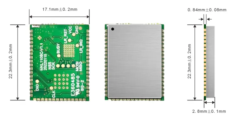
| General | Dimension | 22.3mm*17.1mm*2.8mm(With Shield) |
| Package | SMT | |
| PIN | 50 Pin Half-Hole | |
| Additional Feature | Geolocation (WIFI+Bluetooth+LP GPS) | |
| MCU | NRF52840 | ARM® Cortex™-M4 32-bit processor |
| Flash | 1MB | |
| RAM | 256KB | |
| LoRa Wireless Specification | LoRa Protocol | LoRaWAN V1.0.3 |
| Frequency Plan | EU868/AU915/US915/AS923/IN865/KR920/EU4 33/CN470/CN779/RU864 | |
| Max Transmit Power | Max 22dBm | |
| Sensitivity | -137dBm@SF12 300bps | |
| Range | Up to 10 km (in free space 5dBi) | |
| BLE Wireless Specification | Bluetooth® (BLE) | V 5.3 |
| Max Transmit Power | 8 dBm | |
| Sensitivity | – 95 dBm | |
| Range | Up to 50 m in free space | |
| Power Consumption | Supply Voltage | 2.8V ~ 3.6V |
| Sleep Current | <6uA | |
| Standby Current | <600uA | |
| Max Operation Current | <125mA | |
| Antenna | LoRa Antenna | Stamp Hole |
| BLE Antenna | Stamp Hole | |
| Application Parameter | Operating Temperature | -40 to 85 °C |
| Storage Temperature | -40 to 85 °C | |
| Certification | CE FCC certification in process | |
| Miscellaneous | Lead-free and RoHS compliant |
Mechanical Size
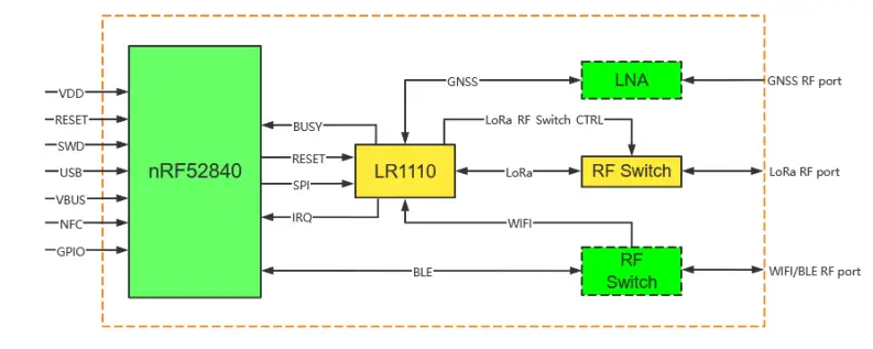
Circuit Design
Block Diagram

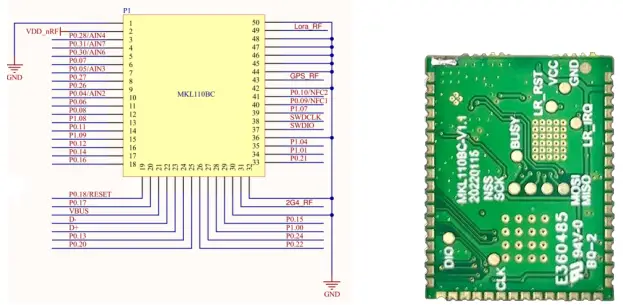
| PIN No. | Name | Type | Function |
| 1 | GND | Power | Ground |
| 2 | VDD_nRF | Power | Power Supply |
| 3 | P0.28 | Digital I/O | General Purpose I/O |
| AIN4 | Analog input 0 | SAADC/COMP/LPCOMP input | |
| 4 | P0.31 | Digital I/O | General Purpose I/O |
| AIN7 | Analog input 0 | SAADC/COMP/LPCOMP input | |
| 5 | P0.30 | Digital I/O | General Purpose I/O |
| AIN6 | Analog input 0 | SAADC/COMP/LPCOMP input | |
| 6 | P0.07 | Digital I/O | General Purpose I/O |
| 7 | P0.05 | Digital I/O | General Purpose I/O |
| AIN3 | Analog input 0 | SAADC/COMP/LPCOMP input | |
| 8 | P0.27 | Digital I/O | General Purpose I/O |
| 9 | P0.26 | Digital I/O | General Purpose I/O |
| 10 | P0.04 | Digital I/O | General Purpose I/O |
| AIN2 | Analog input 0 | SAADC/COMP/LPCOMP input | |
| 11 | P0.06 | Digital I/O | General Purpose I/O |
| 12 | P0.08 | Digital I/O | General Purpose I/O |
| 13 | P1.08 | Digital I/O | General Purpose I/O |
| 14 | P0.11 | Digital I/O | General Purpose I/O |
| 15 | P1.09 | Digital I/O | General Purpose I/O |
| 16 | P0.12 | Digital I/O | General Purpose I/O |
| 17 | P0.14 | Digital I/O | General Purpose I/O |
| 18 | P0.16 | Digital I/O | General Purpose I/O |
| 19 | P0.18 | Digital I/O | General Purpose I/O |
| RESET | Reset | Reserved for reset | |
| 20 | P0.17 | Digital I/O | General Purpose I/O |
| 21 | VBUS | Power | 5 V input for USB controller |
| 22 | D- | USB | USB D- |
| 23 | D+ | USB | USB D+ |
| 24 | P0.13 | Digital I/O | General Purpose I/O |
| 25 | P0.20 | Digital I/O | General Purpose I/O |
| 26 | P0.22 | Digital I/O | General Purpose I/O |
| 27 | P0.24 | Digital I/O | General Purpose I/O |
| 28 | P1.00 | Digital I/O | General Purpose I/O |
| 29 | P0.15 | Digital I/O | General Purpose I/O |
| 30 | GND | Power | Ground |
| 31 | 2G4_RF | RF | Reserved for BLE antenna port |
| 32 | GND | Power | Ground |
| 33 | P0.21 | Digital I/O | General Purpose I/O |
| 34 | P1.01 | Digital I/O | General Purpose I/O |
| 35 | P1.04 | Digital I/O | General Purpose I/O |
| 36 | GND | Power | Ground |
| 37 | SWDIO | Debug | Serial wire debug I/O for debug and programming |
| 38 | SWDLCK | Debug | Serial wire debug clock input for debug and programming |
| 39 | P1.07 | Digital I/O | General Purpose I/O |
| 40 | P0.09 | Digital I/O | General Purpose I/O |
| NFC1 | NFC | Reserved for NFC | |
| 41 | P0.10 | Digital I/O | General Purpose I/O |
| NFC2 | NFC | Reserved for NFC | |
| 42 | GND | Power | Ground |
| 43 | GPS_RF | RF | Reserved for GPS antenna port |
| 44 | GND | Power | Ground |
| 45 | GND | Power | Ground |
| 46 | GND | Power | Ground |
| 47 | GND | Power | Ground |
| 48 | GND | Power | Ground |
| 49 | Lora_RF | RF | Reserved for LoRa antenna port |
| 50 | GND | Power | Ground |
- Note: Please refer to Nordic nRF52840 Product Specifications for detailed descriptions and features supported about the Pin assignments.
Cautions
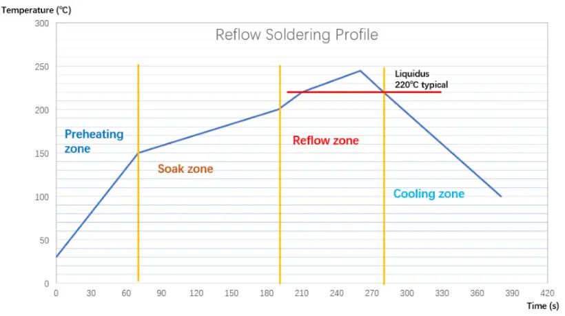
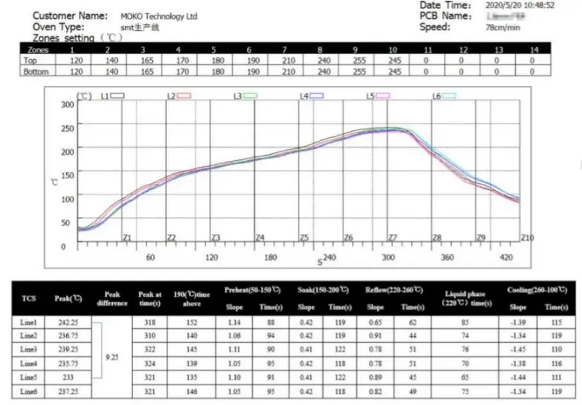
Reflow soldering
- Reflow soldering is a vitally important step in the SMT process. The temperature curve associated with the reflow is an essential parameter to control to ensure the correct connection of parts. The parameters of certain components will also directly impact the temperature curve selected for this step in the process.
The standard reflow profile has four zones:
- preheat,
- soak,
- reflow, and
- cooling. The profile describes the ideal temperature curve of the top layer of the PCB.
- During reflow, modules should not be above 260°C and not for more than 30 seconds.

| Specification | Value |
| Temperature Increase Rate | <2.5°C/s |
| Temperature Decrease Rate | Free air cooling |
| Preheat Temperature | 0-150°C |
| Preheat Period (Typical) | 40-90s |
| Soak Temp Increase Rate | 0.4-1°C/s |
| Soak Temperature | 150-200°C |
| Soak Period | 60-120s |
| Liquidus Temperature (SAC305) | 220°C |
| Time Above Liquidous | 45-90s |
| Reflow Temperature | 230-250°C |
| Absolute Peak Temperature | 260°C |
Usage Condition Notes
- Follow the conditions written in this specification, especially the recommended condition
- ratings about the power supply applied to this product.
- The supply voltage has to be free of AC ripple voltage (for example from a battery or a low
- noise regulator output). For noisy supply voltages, provide a decoupling circuit (for example a
- ferrite in series connection and a bypass capacitor to ground of at least 47Uf directly at the module).
- Take measures to protect the unit against static electricity. If pulses or other transient loads (a
- large load applied in a short time) are applied to the products, check and evaluate their
- operation before assembly on the final products.
- The supply voltage should not be exceedingly high or reversed. It should not carry noise and/or
- spikes.
- This product away from other high frequency circuits.
- Keep this product away from heat. Heat is the major cause of decreasing the life of these
- products.
- Avoid assembly and use of the target equipment in conditions where the products’
- temperature may exceed the maximum tolerance.
- This product should not be mechanically stressed when installed.
- Do not use dropped products.
- Do not touch, damage or soil the pins.
- Pressing on parts of the metal shield or fastening objects to the metal shield will cause damage.
Storage Notes
- The module should not be stressed mechanically during storage.
- Do not store these products in the following conditions or the performance characteristics of
- the product, such as RF performance will be adversely affected:
- Storage in salty air or in an environment with a high concentration of corrosive gas.
- Storage in direct sunlight
- Storage in an environment where the temperature may be outside the range specified.
- Storage of the products for more than one year after the date of delivery storage period.
- Keep this product away from water, poisonous gas and corrosive gas.
- This product should not be stressed or shocked when transported.
FCC STATEMENT
- This device complies with part 15 of the FCC Rules. Operation is subject to the following two conditions:
- This device may not cause harmful interference, and
- this device must accept any interference received, including interference that may cause undesired operation.
- Changes or modifications not expressly approved by the party responsible for compliance could void the user’s authority to operate the equipment.
FCC Radiation Exposure Statement
- The modular can be installed or integrated in mobile or fix devices only. This modular cannot be installed in any portable device, for example, USB dongle like transmitters is forbidden.
- This modular complies with FCC RF radiation exposure limits set forth for an uncontrolled environment. This transmitter must not be co-located or operating in conjunction with any other antenna or transmitter. This modular must be installed and operated with a minimum distance of 20 cm between the radiator and user body.
- If the FCC identification number is not visible when the module is installed inside another device, then the outside of the device into which the module is installed must also display a label referring to the enclosed module. This exterior label can use wording such as the following: “Contains Transmitter Module FCC ID: 2AO94 MKL110BC Or Contains FCC ID: 2AO94-MKL110BC”
When the module is installed inside another device, the user manual of this device must contain below warning statements:
- This device complies with Part 15 of the FCC Rules. Operation is subject to the following two conditions:
- This device may not cause harmful interference, and
- This device must accept any interference received, including interference that may cause undesired operation.
- Changes or modifications not expressly approved by the party responsible for compliance could void the user’s authority to operate the equipment.
- The devices must be installed and used in strict accordance with the manufacturer’s instructions as described in the user documentation that comes with the product.
- The host product manufacturer is responsible for compliance to any other FCC rules that apply to the host not covered by the modular transmitter grant of certification.
- The final host product still requires Part 15 Subpart B compliance testing with the modular transmitter installed.
- The end user manual shall include all required regulatory information/warning as shown in this manual, include:
- This product must be installed and operated with a minimum distance of 20 cm between the radiator and user body.
- MOKO TECHNOLOGY LTD.
![]()
- 4F, Buidling2, Guanghui Technology Park, MinQing Rd, Longhua, Shenzhen, Guangdong, China
- Tel:86 755 23573370 829
- Support_[email protected]
- https://www.mokosmart.com
- www.mokosmart.com


