
VMAC A240104 OEM Compressor Mount Package for 70CFM Stage V Cummins Instruction Manual
Important Information
The information in this manual is intended for approved VMAC installers who have been trained in installation and service procedures and/or for anyone with mechanical trade certification who have the tools and equipment to properly and safely perform the service. Do not attempt this service without the appropriate mechanical training, knowledge, and experience. Follow all safety precautions for mechanical work. Any fabrication for correct fit inequipment must follow industry standard “best practices”.
Notice
Copyright © 2023 VMAC Global Technology Inc. All Rights Reserved. These materials are provided by VMAC for informational purposes only, without representation or warranty of any kind, and VMAC shall not be liable for errors or omissions with respect to the materials. The only warranties for VMAC products and services are those set forth in theexpress warranty statements accompanying such products and services, if any, and nothing herein shall be construed as constituting an additional warranty. Printing or copying of any page in this document in whole or in part is only permitted for personal use. All other use, copying or reproduction in both print and electronic form of any part of this document without the written consent of VMAC is prohibited. The information contained herein may be changed without prior notice.
General Information
Introduction
This manual provides installation instructions for mounting the engine related compressor components. Read this manual prior to servicing or operating the compressor system. Follow all safety precautions when servicing or operating the VMAC system. Proper service and repair are important to the safety of the operator and the safe, reliable operation of the equipment. Always use genuine VMAC replacement parts. The procedures described in this manual are the only approved methods of service and operation.
Torque Specifications
All fasteners must be torqued to specifications. Use manufacturers’ torque values for OEM fasteners. Apply Loctite 242 (blue) or equivalent on all engine-mounted fasteners. Torque values are with Loctite applied unless otherwise specified.
| Standard Grade 8 National Coarse Thread | ||||||||
| Size | 1/4 | 5/16 | 3/8 | 7/16 | 1/2 | 9/16 | 5/8 | 3/4 |
| Foot-pounds (ft-lb) | 9 | 18 | 35 | 55 | 80 | 110 | 170 | 280 |
| Newton meter (N•m) | 12 | 24 | 47 | 74 | 108 | 149 | 230 | 379 |
| Standard Grade 8 National Fine Thread | |||||
| Size | 3/8 | 7/16 | 1/2 | 5/8 | 3/4 |
| Foot-pounds (ft-lb) | 40 | 60 | 90 | 180 | 320 |
| Newton meter (N•m) | 54 | 81 | 122 | 244 | 434 |
| Metric Class 10.9 | ||||||
| Size | M6 | M8 | M10 | M12 | M14 | M16 |
| Foot-pounds (ft-lb) | 4.5 | 19 | 41 | 69 | 104 | 174 |
| Newton meter (N•m) | 6 | 25 | 55 | 93 | 141 | 236 |
Ordering Parts
To order parts, contact the VMAC Inside Sales department. To assist in selecting the appropriate parts, please provide the VMAC compressor serial number, part number, description, and quantity. Contact VMAC Inside Sales by calling 1 (887) 912-6605 or by email to [email protected].
Safety
Important Safety Notice
The information contained in this manual is based on sound engineering principles, research, extensive field experience and technical information. Information is constantly changing with the addition of new models, assemblies, service techniques and running OEM changes. If a discrepancy is found in this manual, contact the VMAC OEM department prior to initiating or proceeding with installation, service or repair. Current information may clarify the issue. Anyone with knowledge of such discrepancies, who proceeds to perform service and repair, assumes all risks. Only proven service procedures are recommended. Anyone who departs from the specific instructions provided in this manual must first assure that their safety and that of others is not being compromised, and that there will be no adverse effects on the operational safety or performance of the equipment. VMAC will not be held responsible for any liability, consequential damages, injuries, loss or damage to individuals or to equipment as a result of the failure of anyone to properlyadhere to the procedures set out in this manual or standard safety practices. Safety should be the first consideration when performing any service operations. If there are any questions concerning the proceduresin this manual, or more information is required, please contact VMAC OEM department prior to beginning repairs.
Safety Messages
This manual contains various warnings, cautions and notices that must be observed to reduce the risk of personal injury during installation, service or repair and the possibility that improper installation, service or repair may damage the equipment or render it unsafe.
![]() This symbol is used to call attention to instructions concerning personal safety. Watch for this symbol; it points out important safety precautions, it means, “Attention, become alert! Your personal safety is involved”. Read the message that follows and be aware of the possibility of personal injury or death. As it is impossible to warn of every conceivable hazard, common sense and industry standard safety practices must be observed.
This symbol is used to call attention to instructions concerning personal safety. Watch for this symbol; it points out important safety precautions, it means, “Attention, become alert! Your personal safety is involved”. Read the message that follows and be aware of the possibility of personal injury or death. As it is impossible to warn of every conceivable hazard, common sense and industry standard safety practices must be observed.
 This symbol is used to call attention to instructions on a specific procedure that if not followed may damage or reduce the useful life of the compressor or other equipment.
![]() This symbol is used to call attention to additional instructions or special emphasis on a specific procedure.
This symbol is used to call attention to additional instructions or special emphasis on a specific procedure.
Safety Precautions
![]() As it is impossible to warn of every possible hazard that may result from operating this system, common sense and industry standard safety practices must be observed.
As it is impossible to warn of every possible hazard that may result from operating this system, common sense and industry standard safety practices must be observed.
Read this information before operating the compressor for the first time. Follow the information and procedures in this manual for operation, maintenance and repair. Observe the following items to reduce the chance of personal injury or equipment damage. Proper service and repair are important to the safety of the service technician and the safe, reliable operation of the equipment. Always use genuine VMAC replacement parts. The procedures described in this service manual are effective methods of service and repair. Some procedures may require the use of tools specially designed for a specific purpose. Anyone using a replacement part, service procedure or tool must first determine that neither their safety nor the safe operation of the equipment will be compromised by the replacement part, service procedure or tool selected.
 Moving Parts Hazard
- Before performing service, disconnect the power source to prevent unexpected equipmentstart.
- Do not operate the system without guards in place. If the guards are damaged or missing, replace them before operating the equipment.
 Electrical Hazard
- Ensure the ground point connection is connected to the equipment body/chassis to prevent the chance of injury.
- Ensure the equipment is grounded appropriately.
 Burn Hazard
- The compressor system gets very hot during operation, contact with the components or the oil can cause serious injury. Allow sufficient time for the system to cool prior to performing service.
- Never allow any part of your body to contact the compressor components until the system has cooled sufficiently
Compressor Air and Oil Hazard
- The compressor system is under sufficient pressure that a leak could force the air/oil mixture through the skin directly into your bloodstream. This could cause serious injury or death.
- Ensure the system is completely depressurized before attempting maintenance or repair.
- Do not use compressed air to clean off clothing or skin, compressed air can penetrate the skin causing serious injury or death.
- Do not move or service the system while it is pressurized or operating.
- Components and hoses under pressure could separate suddenly and cause serious injury or death. If equipped, the air receiver tank must be drained prior to servicing the system.
- Never adjust or attempt to make any repairs to the system while the engine is running. Components and hoses under pressure could fail and cause serious injury or death.
![]() Burst Hazard
Burst Hazard
- Serious injury or death may result from an air tank explosion.
- Never exceed manufacturer’s maximum air pressure rating.
- Do not repair components, only replace with approved parts.
- Do not tamper with, or disable factory safety equipment.


 Personal Safety
- Vaporized oil is a respiratory hazard, do not breathe the compressor air.
- Always use the appropriate personal protective equipment, particularly eye and hearing protection when operating air powered equipment.
Main Bracket and Compressor Installation
Apply Loctite 242 (blue) to all fasteners.
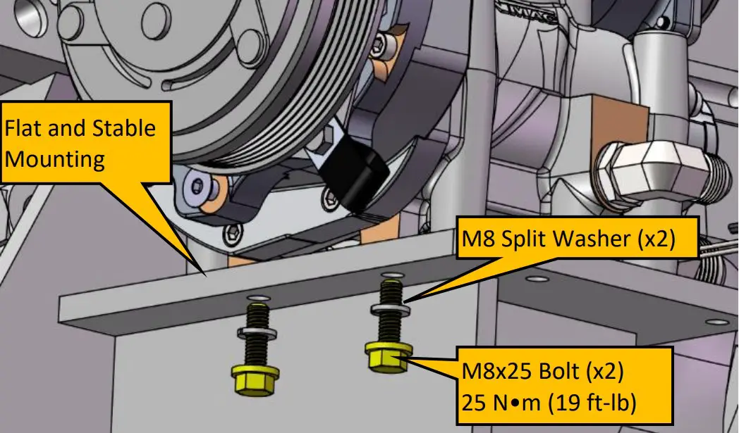
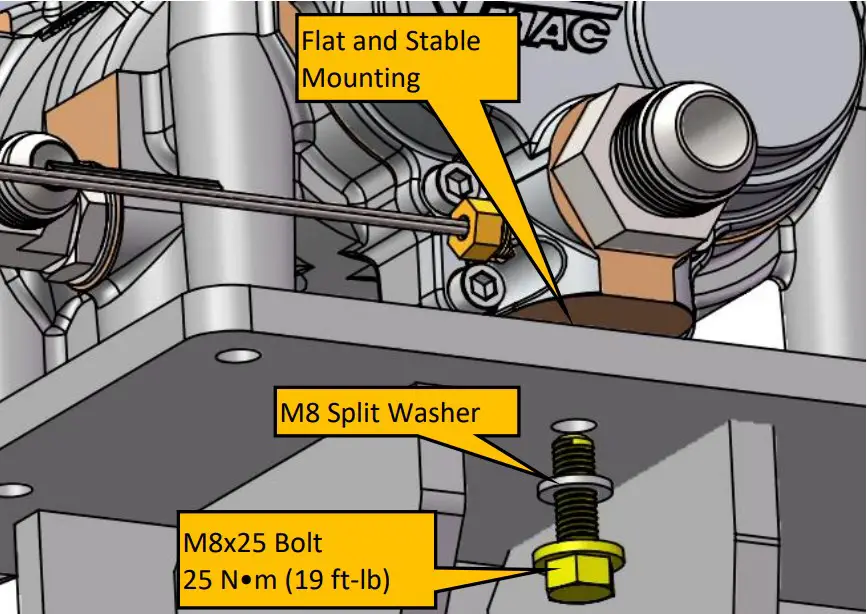
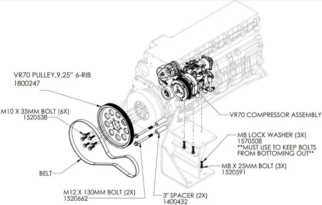
- Place the compressor on the pedestal and fasten using the three M8x25 bolts and split washers. Ensure compressor is mounted on a flat and stable surface the compressor mounting points all contact the pedestal. Leave the bolts a little loose for now to assist with alignment of bracket assembly to engine in the next steps. See Figure 1 and Figure 2 for mounting locations.


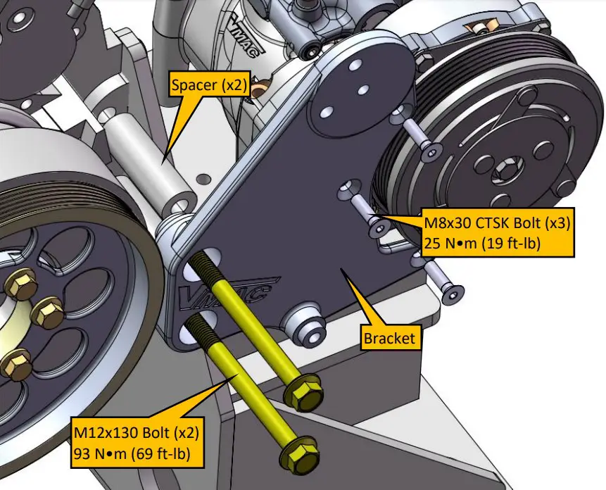
- Apply blue Loctite and install the three M8x30 flathead countersink bolts through the bracket onto the compressor as shown in Figure 3. Leave the bolts a little loose for now to place the spacers in behind the bracket.
- Place the spacers between the bracket and the engine, apply Loctite and install the two M12x130 bolts through the bracket and spacers onto the engine as shown in Figure 3. Snug bolts up finger tight.
- Snug up the three M8x30 flathead countersink bolts. As these are tightened note any flexing or pulling of any part of the assembly as this may indicate an alignment or interference issue. Ensure that there is no play with the spacers, or any gaps between the compressor and bracket and engine.
- Once all fasteners are snug and everything looks good, tighten bolts to specifications in the following order: first the three M8 flathead countersink bolts, then two M12 bolts, then finally the three compressor bolts & nuts.

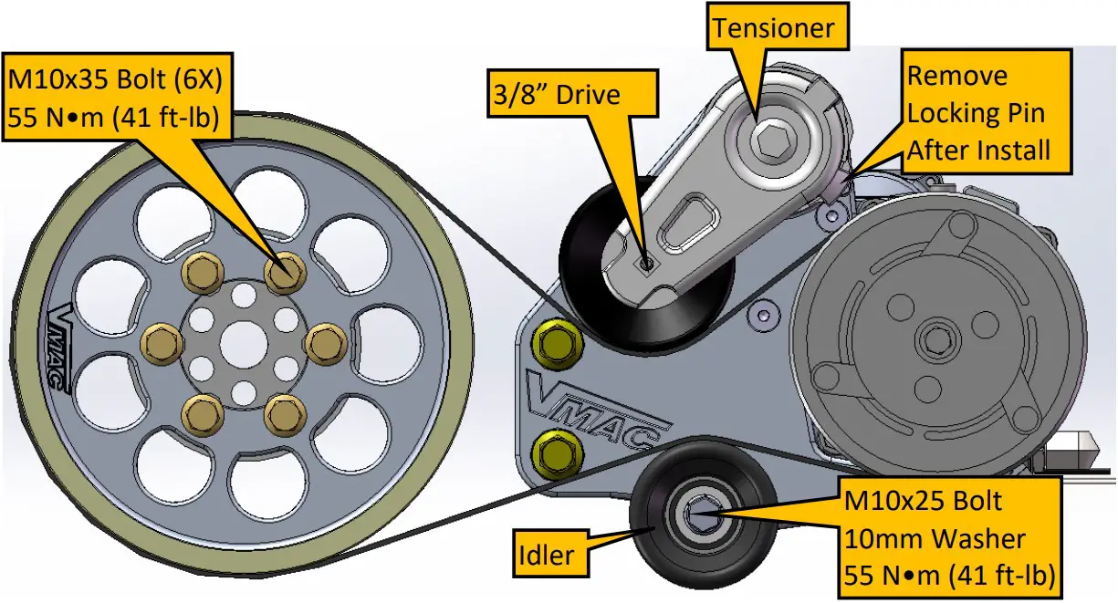
- Install crank pulley. The pulley bolts onto the OEM crank pulley. Use blue Loctite and the six M10 X 35 bolts provided. Torque to specifications.
- Install the tensioner using the fasteners provided.
- Install the idler as shown in Figure 4 using the M10x25 bolts and washers provided.
- Install belt and route as per Figure 4.
- Remove the tensioner locking pin using a 3/8” drive to rotate the tensioner.


Hydraulic Lock Condition
- The Hydraulic Lock condition should be reduced or eliminated as the condition can cause premature clutch and/or compressor failure.
- It is best practice to mount the cooler and oil separation below the level of the compressor to prevent hydraulic lock. If mounting these components above the compressor is required, a check valve is to be installed.
Hydraulic lock can occur when any of the supplementary oil system components (separator system, oil cooler, or thermostatic valve) are installed at a higher heightthan the compressor. When this happens, the weight of the oil in the line can cause the oil to drain into the compressor after system shutdown. When this occurs, the compressor rotors experience much higher than normal load at the next start-up as the oil is pumped out of the compressor. This can cause excessive clutch slipping,excessive wear, and shortened clutch and compressor life along with potential belt and bearing overload. To prevent hydraulic lock from occurring, a check valve with a 5psi cracking pressure can be installed on the oil return line to the compressor to prevent oil from draining into the compressor.
Further information and installation instructions are included with the VMAC check valve kit A270102.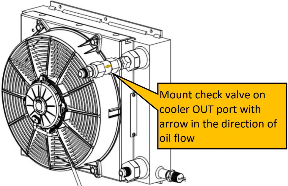
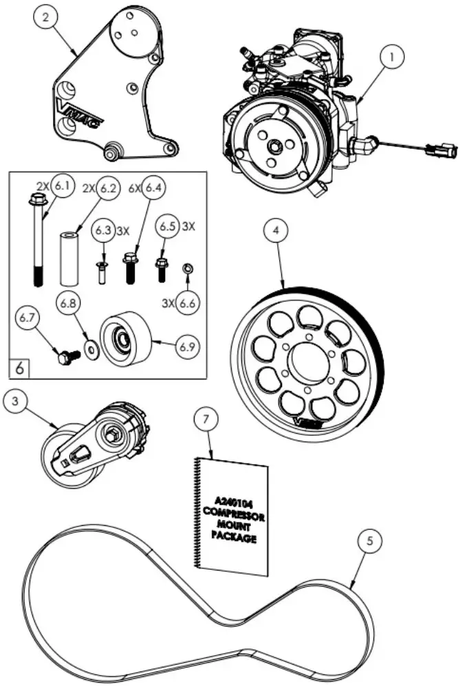
Engine Package – A240104
| Item # | Part # | Qty | Description |
| 1 | P120218 | 1 | ASSEMBLY, COMPRESSOR, VR70 |
| 2 | 1201120 | 1 | BRACKET, CUMMINS B4.5/6.7 STAGE V |
| 3 | 3300036 | 1 | TENSIONER 7C3Z-6B209-D |
| 4 | 1800247 | 1 | PULLEY, 6-RIB, CUMMINS |
| 5 | 1610342 | 1 | BELT, K060547 |
| 6 | 3801383 | 1 | FASTENER PACK, A240104 |
| 6.1 | 1520662 | 2 | BOLT, HHCS G10.9, M12X1.75X130FLPL |
| 6.2 | 1400432 | 2 | SPACER, TENSIONER BRACKET |
| 6.3 | 1540565 | 3 | BOLT, FLHDSCKT M8X1.25X30,GR10.9 PLT |
| 6.4 | 1520538 | 6 | BOLT, HHCS, FLHD, M10 X 1.50 X 35 |
| 6.5 | 1520591 | 3 | BOLT, HHCS, M8-1.25 X 25, G10.9 FL PL |
| 6.6 | 1570508 | 3 | WASHER, SPLIT LOCK, M8, PLATED |
| 6.7 | 1520563 | 1 | BOLT, HHCS FLPL G8.8 M10 X1.50 X 25 |
| 6.8 | 1570496 | 1 | WASHER, FENDER, 10MM X 30MM |
| 6.9 | 1300045 | 1 | IDLER, BACK, 8-RIB, 76MM |
| 7 | 1901132 | 1 | INSTRUCTIONS/IPL, A240104 |
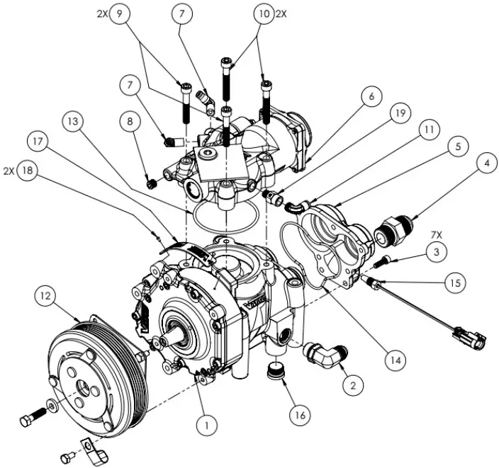
Compressor Assembly – P120218
| Item # | Part # | Qty | Description |
| 1 | 9200636 | 1 | SUB ASSY, VR70, 3.21 |
| 2 | 4900203 | 1 | FTG, 90, #8MORB-#8MJIC, VITON |
| 3 | 1540549 | 7 | BOLT,SHCS,M6 X 1 X 18,PLATED,G12.9 |
| 4 | 4900128 | 1 | FTG, STR, #12MORB-#12MJIC, VITON |
| 5 | 9200510 | 1 | CAP, DISCHARGE, VR70 |
| 6 | 9200610 | 1 | ASSY, INLET, 2.0” INTAKE |
| 7 | 5000165 | 2 | ELBOW,90, BRASS NPT-POLY, 1/8-3/16 |
| 8 | 4300076 | 1 | PIPE FTG, PLUG SKT HEAD, 1/8 |
| 9 | 1540550 | 2 | BOLT,SHCS,M8 X 1.25 X 50, G12.9 PLT |
| 10 | 1540530 | 2 | BOLT,SHCS,M8 X 1.25 X 55, G12.9 PLT |
| 11 | 5000020 | 1 | ELBOW, BRASS NPT-POLY, 1/8-1/4 |
| 12 | P200035 | 1 | CLUTCH, COMPLETE 6 GROOVE |
| 13 | 5830004 | 1 | O-RING, VITON, 3 1/8 ID X 1/8 |
| 14 | 5830112 | 1 | O-RING, VITON, 3 3/4 ID X 3/32 |
| 15 | 3550794 | 1 | PROBE, ASSY, THERMISTOR. GT 150 |
| 16 | 4900045 | 1 | PLUG, #8ORB, INTERNAL HEX |
| 17 | 4400295 | 1 | LABEL, VR70 NAME PLATE |
| 18 | 1500355 | 2 | SCREW, LONG U DRIVE, 2 – 3/16 |
| 19 | 3600123 | 1 | VALVE, CHECK, 1/8 NPT |
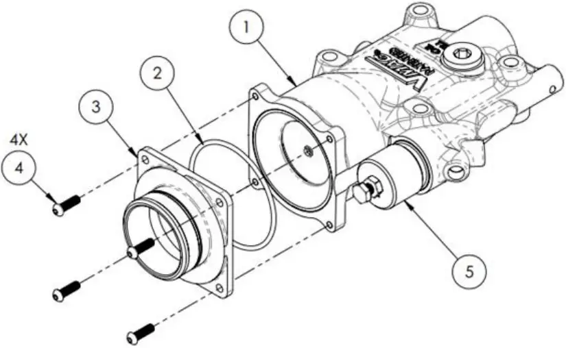
Inlet Valve Assembly – 9200610
| Item # | Part # | Qty | Description |
| 1 | 9200578 | 1 | INLET VALVE, BASIC INTEGRATED REG. |
| 2 | 5830070 | 1 | O-RING, VITON, 2 9/16 ID X 3/32 |
| 3 | 3200545 | 1 | ADAPTER, INLET, 2” |
| 4 | 1500533 | 4 | SCREW, BUTTON HCS, 10-32 X 5/8 PL |
5 | 3600046 | 1 | KIT, REGULATOR |
VMAC – Vehicle Mounted Air Compressors
VMAC Technical Support: 888-241-2289
VMAC Knowledge Base: https://kb.vmacair.com


