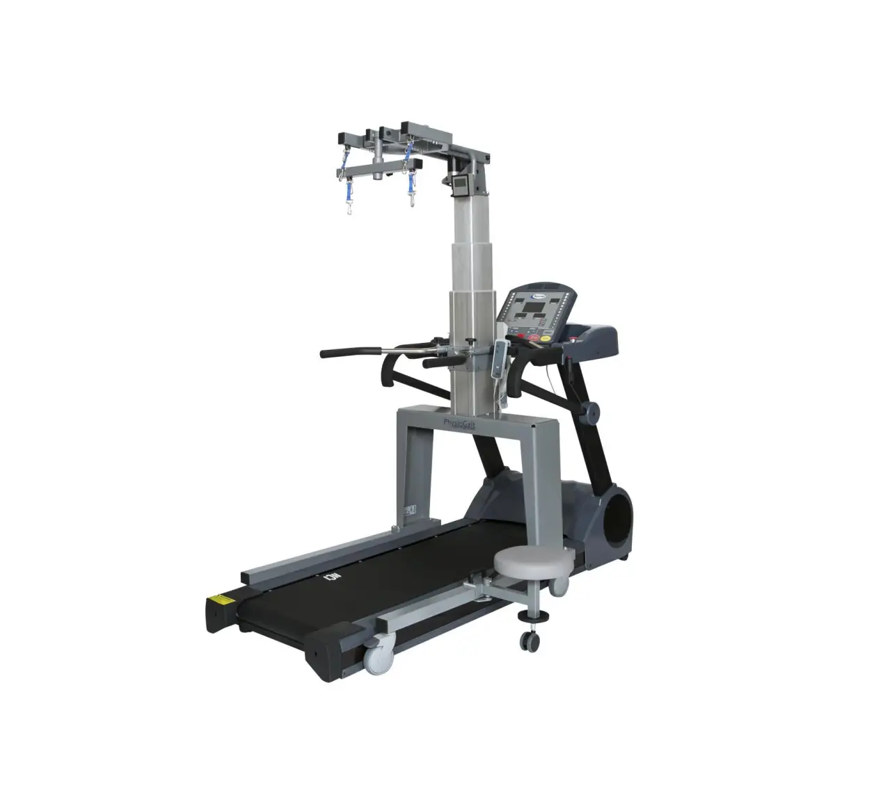
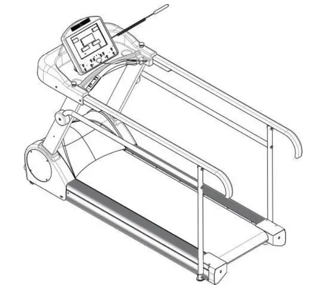
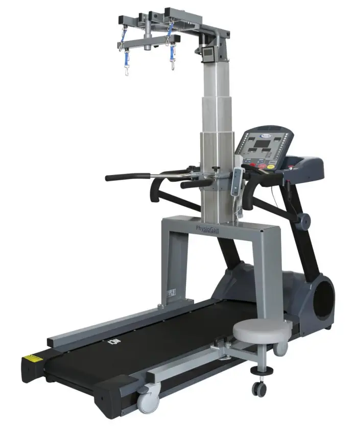
HCI Fitness PhysioMill Rehabilitation Treadmill
Safety Precautions
This exercise equipment was designed and built for optimum safety. However, certain precautions apply whenever you operate a piece of exercise equipment. Be sure to read the entire manual before assembly and operation of this machine.
Also, please note the following safety precautions:
- Read all instructions carefully before using the machine.
- Consult your physician or other health care professional before beginning this or any type of exercise program.
- Always wear proper exercise apparel when using the machine.
- If at any time you feel faint, light-headed or dizzy while operating the machine, stop exercise immediately. You should also stop exercising if you are experiencing pain or pressure.
- Keep children and pets away from the machine while in use.
- Only one person can use the machine at a time.
- Make sure your machine is correctly assembled before you use it. Be sure all screws, nuts, and bolts are tightened prior to use and retighten periodically.
- Do not operate this or any exercise equipment if it is damaged.
- Keep hands and feet away from any moving parts. Do not insert any objects into any openings.
- Keep clothes, jewelry and loose items away from moving parts.
NOTE:
MAXIMUM WEIGHT CAPACITY FOR THE PHYSIOMILL IS 500 LBS. (227 KGS)
 WARNING:
BEFORE BEGINNING ANY EXERCISE PROGRAM CONSULT YOUR PHYSICIAN. THIS IS ESPECIALLY IMPORTANT FOR INDIVIDUALS OVER THE AGE OF 35 OR PEOPLE WITH PRE-EXISTING HEALTH PROBLEMS. READ ALL INSTRUCTIONS BEFORE USING THIS FITNESS EQUIPMENT. WE ASSUME NO RESPONSIBILITY FOR PERSONAL INJURY OR PROPERTY DAMAGE SUSTAINED BY OR THROUGH THE USE OF THIS PRODUCT.
Dear Valued Customer,
Thank you for your recent purchase of the PhysioMill from HCI Fitness.
We believe that you have purchased one of the highest quality and affordable rehabilitation treadmills on the market today. Priorto using your new PhysioMill please review the owner’s manual and product tips to maximize your experience. Wishing you the best of luck in reaching your health and fitness goals!
HealthCare International is aleading supplier and distributor of innovative products for Health, Wellness, Fitness & Active Aging. Visit our website –www.HCIFitness.com for information on all of our products.
Warranty Information
(Your Serial Number is found on a white sticker at the rear base of the unit, the front of the user manual, and on the box)
Serial #: Purchase Date:
5 Year Parts Warranty, 1 Year Labor, Lifetime Main Frame
NOTE
Before you start to assemble this unit, please note that some of the parts andscrews needed for assembly are already in place on the unit.
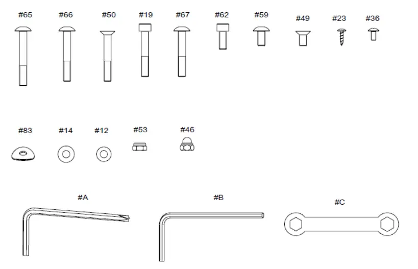
SCREW AND TOOL SET
| NO. | Description | Qty |
| 065 | Mushroom Head Hexagonal Bolt M8*60L | 2 |
| 066 | Mushroom Head Hexagonal Bolt M8*55L | 2 |
| 050 | Hexagonal Bolt M8*55L | 4 |
| 019 | Mushroom Hexagonal Bolt M8*50L | 8 |
| 067 | Mushroom Head Hexagonal Bolt M8*50L | 4 |
| 062 | Mushroom Head Hexagonal Bolt M8*20L | 4 |
| 059 | Mushroom Head Hexagonal Bolt M8*16L | 4 |
| 049 | Hexagonal Bolt M8*16L | 4 |
| 023 | Metal screws TP4*16L | 8 |
| 036 | Cross Screw M5*10L | 4 |
| 083 | Washer 8*25*1.5T | 10 |
| 014 | Washer 8*18*1.5T | 20 |
| 012 | Washer 8*16*1.2T | 2 |
| 053 | Nylon Nut M8 | 4 |
| 046 | Nylon Nut M8 | 4 |
| A | Allen Key 6 mm “+” | 1 |
| B | Allen Key 5 mm | 1 |
| C | Wrench 13*14mm | 1 |
Assembly Instructions
STEP 1: Wire Pinch Point:
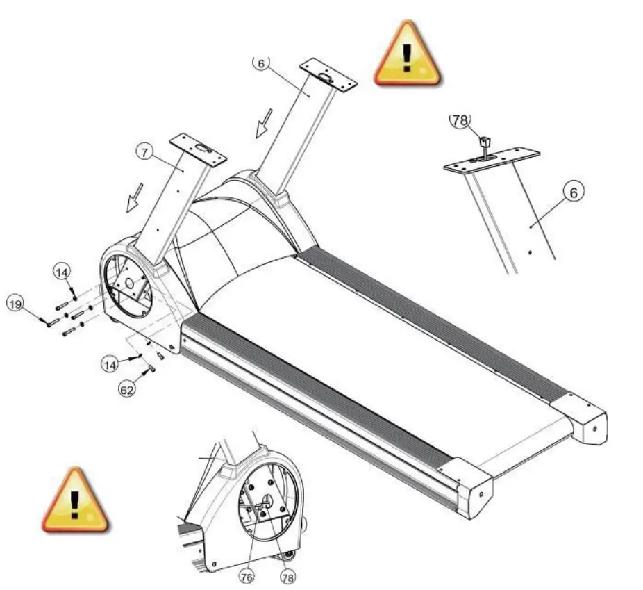
Insert the Upright Posts (6) (7) to the main base, then loosely tighten the Hexagon Head Bolts (19) (62) and Flat Washer (14) to temporarily secure.
Do Not Tighten Bolts Completely Until Step 4
STEP 2:
Wire Pinch Point:
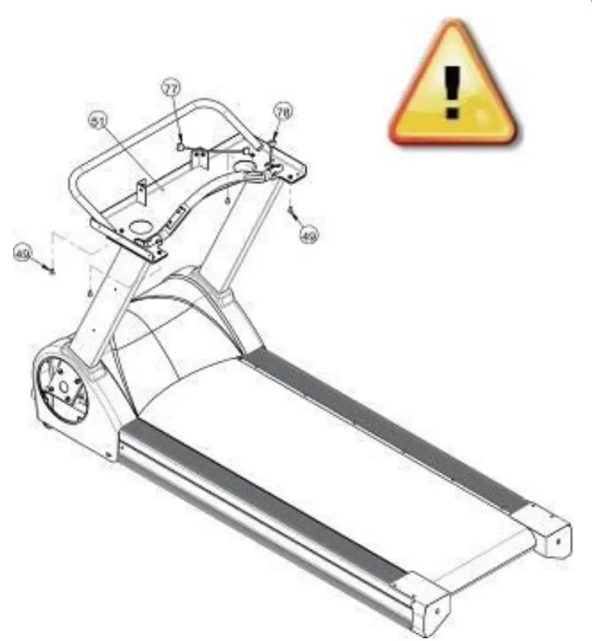
Do Not Tighten Computer Rack Completely Until Step 4
- Place Computer Rack (51) on top of Upright poles and loosely screw in the Hexagonal Bolts (49).
- Take hold of Middle Sensor Cable Wire (78) connect with the Upper Sensor Cable Wire (77) firmly.
STEP 3:
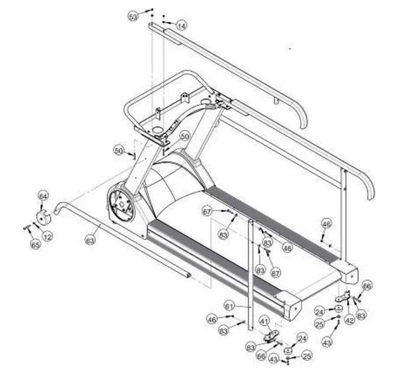
Loosely connect the Hand Rails (52) to the computer rack with the nut on the top. Then secure the handrails to the upright posts with side caps (64), washers (12) and hex bolts (65).
STEP 4:
Completely tighten the nuts and bolts from Steps 1-3. Start with Step 1 and tighten down the bolts that support the Upright Posts. Then tighten the bolts in Step 2 that hold the computer rack in place. Finally, tighten the nuts and bolts that secure the handrails in Step 3.
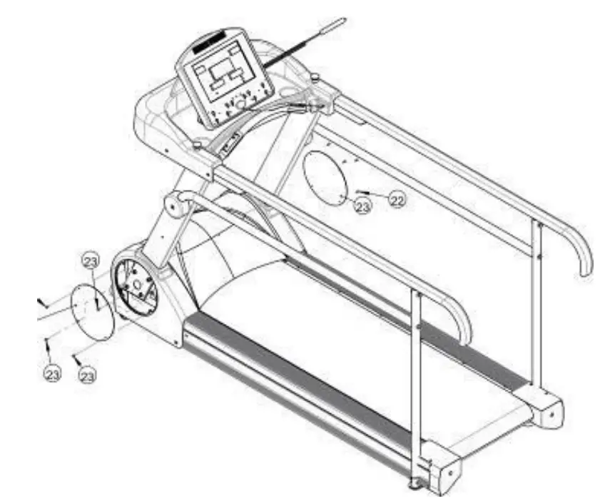
STEP 5:
Place the display rack cover (57) as per drawing. Use screws (36) to secure the shroud. Make sure not to pinch any electrical wires
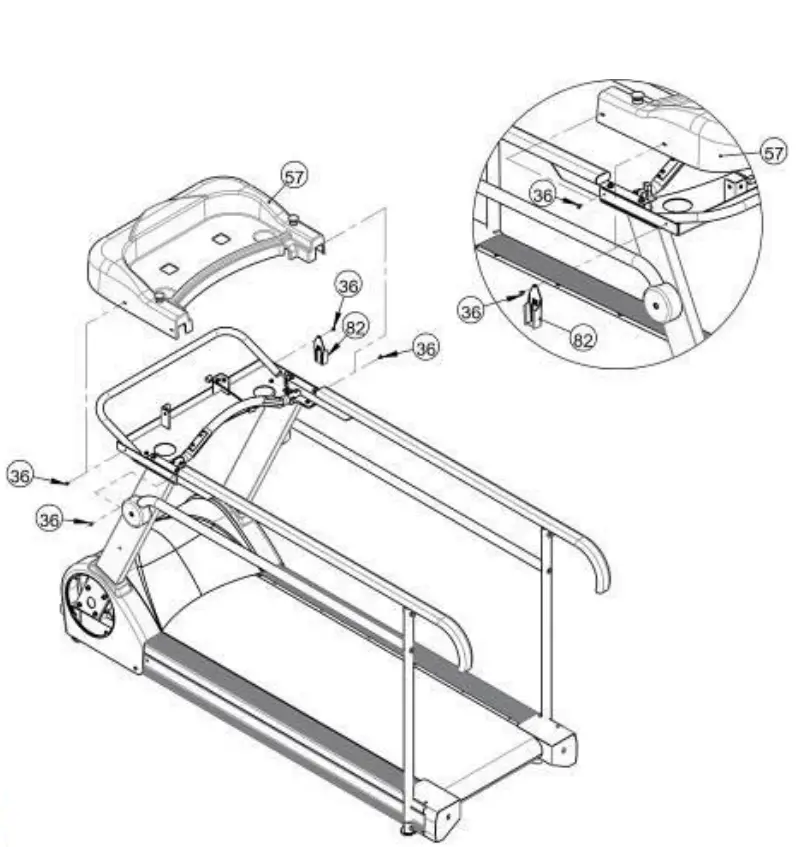
Wire Pinch Point:
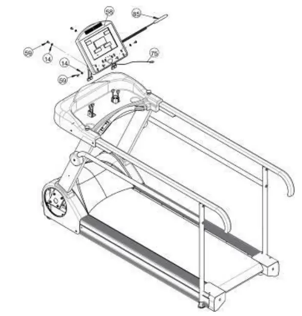
Hold the display (58) and connect the computer sensor wire with the upper pulse sensor wire in advance. Install the display on to the display brackets using the Mushroom Head Hexagonal Bolt (59) and Washer (14) screw tightly.
STEP 7:
After the treadmill is assembled, reattach the Motor Side Covers (22) with screws (23). Your PhysioMill is now completed.
Lubricate belt before use
Before use, please read the safety precautions carefully. Periodically retighten screws and bolts as needed.
Electrical Connection
The Physio Mill needs to be plugged into a standard electrical outlet. The AC adaptor is connected at the front of the unit. The power switch must be on for operation.
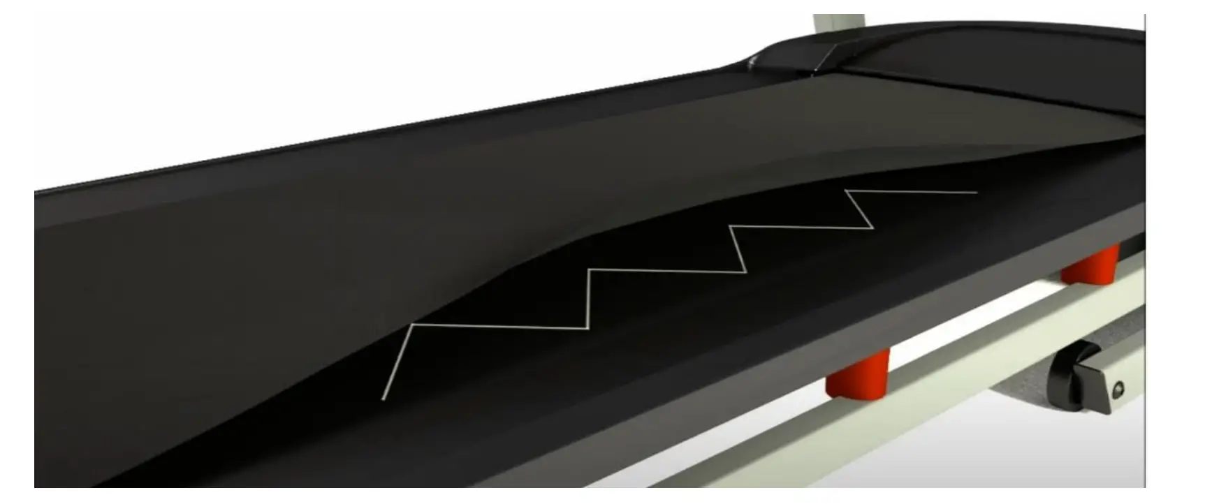
Treadmill Belt Lubrication
Lubricate Belt Before First Use and Every 3 Months or 130 Miles
- Unplug PhysioMill Power from wall.
- Loosen Treadmill Belt 2 turns on each side.
- Apply Lubricant to the Center of the Treadmill Deck in Zig- Zag pattern.
- Tighten Treadmill Belt 2 turns on each side
- Plug in PhysioMill Power to wall.
- Ensure Proper Belt Alignment
- Walk on Treadmill for 5 Minutes to spread lubricant
Scan below with your phone camera to watch this helpful video

Sample Image of Zig Zag Application Pattern
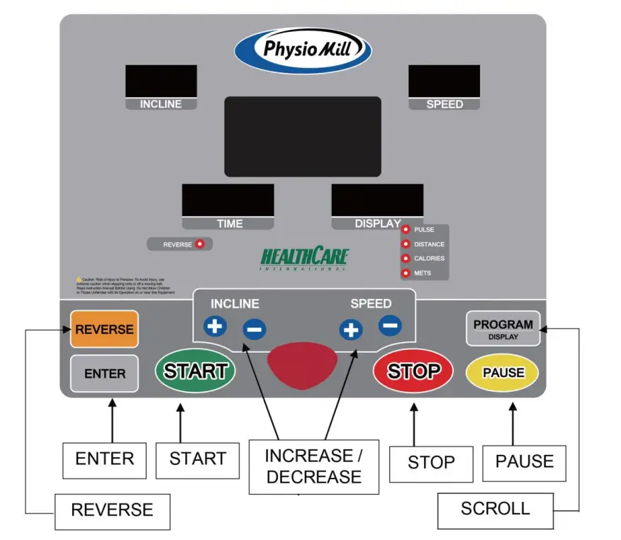
Physio Mill Display Console
Hand-Held Therapy Start / Stop Remote
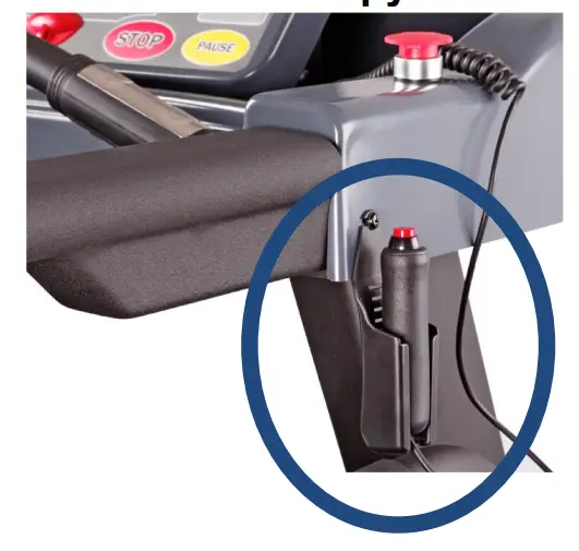
Allows for therapists to start and stop the treadmill while performing hands on rehabilitation.
Simply press the button once to pause the session.
Then press the button again to resume the treadmill belt.
In case of an Emergency, use the Emergency Stop Button located on either side of the console to quickly stop the treadmill belt.
- STARTBUTTON
1.1.Pressing the START button starts the treadmill. - STOP BUTTON
2.1. Pressing the STOP button strops the treadmill. - PAUSE BUTTON
3.1. Pressing the PAUSE button pauses your session. - [+] BUTTON
4.1. . Press the [+]button to increase values.
4.2. . Holding the [+]button will rapidly increase values. - [-] DOWN BUTTON
5.1. Press the [-] button to decrease values.
5.2. Holding the [-] button will rapidly decrease values. - DISPLAY / PROGRAMS BUTTON
6.1. Scrolls through Pulse, Distance, Calories, & METs.
6.2. PROGRAMS MN→P1→…→P12→H1→H2→MN - ENTER BUTTON
7.1. The ENTER button allows for data entry. - REVERSE BUTTON
8.1.To switch the belt direction to reverse follow this sequence.
8.1.1. Press the PAUSE button.
8.1.2. Press the REVERSE button.
8.1.3. Press the START button.
To Return to Forward Repeat 8.1.1 – 8.1.3
General Maintenance
- Cleaning – Use soap and warm water or antibacterial wipes (GREY) toclean the surface of your unit.
- Tightenng – Periodically inspect your unit to ensure that all screws, nuts, and bolts are tightened and retighten if necessary. Do not over tighten
- Belt Lubrication – Every 3 Months or 130 Miles. See page 9.
Trouble Shooting
ERROR 1 (E1):
When power on treadmill and press START key, the computer cannot read speed signal from motor in 7 seconds:
When treadmill on “RUN MODE” status, monitor display “E1” and makes “BEEP” sound if treadmill didn’t read speed signal from motor in 7 seconds. ERROR1 causes: It’s possible that motor speed sensor cable has been damaged;
incorrect installment of position or the speed sensor cable didn’t be connected correct to motor control board.
ERROR 6 (E6):
When drive the incline motor and, the computer cannot read VR value from incline motor in 6 seconds:
The monitor flashes “E6” and makes BEEP sound per second if computer didn’t read VR value from incline motor in 6 seconds. ERROR6 causes: It’s probably that VR sensor of incline motor has been damaged. Or 2.5pitch of 3 PIN connector didn’t correctly connect to socket of motor control board. Perhaps one of the power cable of incline motor has been dropped (Power cord; UP with red color, Down with black and COM with white). Above causes could lead incline motor does not work and VR value unchanging and show E6.
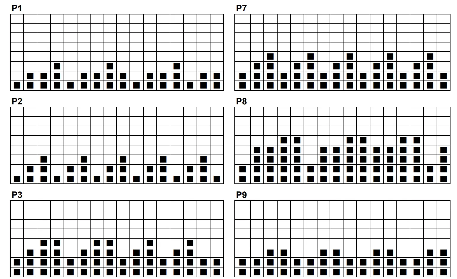
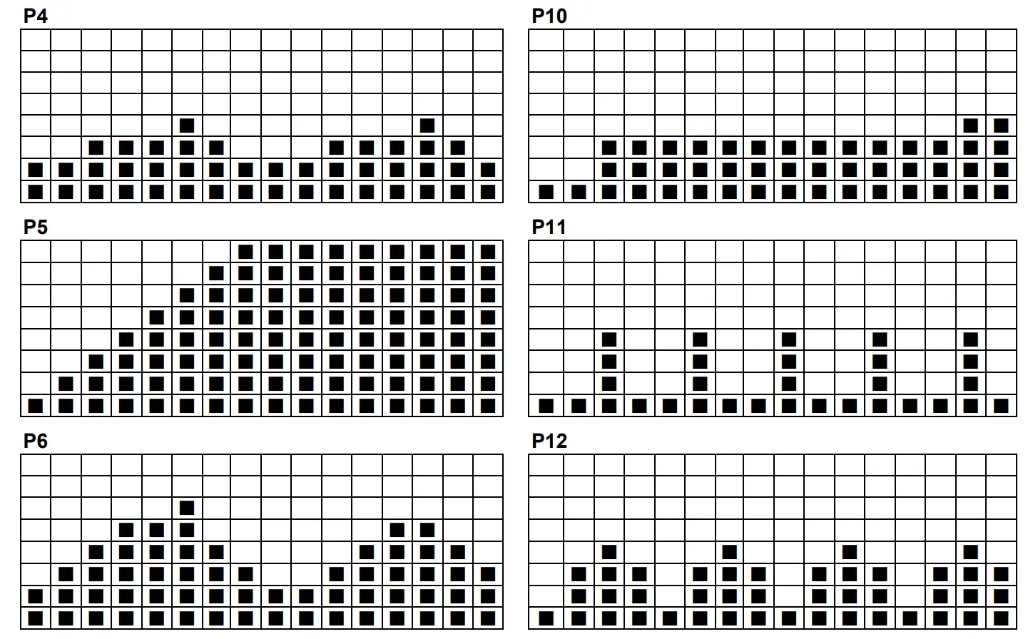
Programs Operating
PROGRAM (KPH)
| SPEED INCLUDE | P1 | P2 | P3 | P4 |
| LEVEL 1 | ||||
| Interval 1 | 2.0 KPH/0 INC | 2.0 KPH/0 INC | 3 KPH/0 INC | 3 KPH/0 INC |
| Interval 2 | 3.0 KPH/0 INC | 4.0 KPH/0 INC | 6 KPH/0 INC | 3 KPH/0 INC |
| Interval 3 | 4.0 KPH/0 INC | 6.0 KPH/0 INC | 8 KPH/0 INC | 5 KPH/0 INC |
| Interval 4 | 5.0 KPH/0 INC | 2.0 KPH/0 INC | 8 KPH/0 INC | 6 KPH/0 INC |
| Interval 5 | 2.0 KPH/0 INC | 4.0 KPH/0 INC | 3 KPH/0 INC | 7 KPH/0 INC |
| Interval 6 | 3.0 KPH/0 INC | 6.0 KPH/0 INC | 6 KPH/0 INC | 8 KPH/0 INC |
| Interval 7 | 4.0 KPH/0 INC | 2.0 KPH/0 INC | 8 KPH/0 INC | 6 KPH/0 INC |
| Interval 8 | 5.0 KPH/0 INC | 4.0 KPH/0 INC | 8 KPH/0 INC | 4 KPH/0 INC |
| Interval 9 | 3.0 KPH/0 INC | 6.0 KPH/0 INC | 3 KPH/0 INC | 3 KPH/0 INC |
| Interval 10 | 2.0 KPH/0 INC | 2.0 KPH/0 INC | 6 KPH/0 INC | 3 KPH/0 INC |
| Interval 11 | 3.0 KPH/0 INC | 4.0 KPH/0 INC | 8 KPH/0 INC | 5 KPH/0 INC |
| Interval 12 | 4.0 KPH/0 INC | 6.0 KPH/0 INC | 3 KPH/0 INC | 6 KPH/0 INC |
| Interval 13 | 5.0 KPH/0 INC | 2.0 KPH/0 INC | 6 KPH/0 INC | 7 KPH/0 INC |
| Interval 14 | 2.0 KPH/0 INC | 4.0 KPH/0 INC | 8 KPH/0 INC | 8 KPH/0 INC |
| Interval 15 | 3.0 KPH/0 INC | 6.0 KPH/0 INC | 3 KPH/0 INC | 6 KPH/0 INC |
| Interval 16 | 4.0 KPH/0 INC | 2.0 KPH/0 INC | 3 KPH/0 INC | 4 KPH/0 INC |
| SPEED INCLUDE | P5 | P6 | P7 | P8 |
| LEVEL 1 | ||||
| Interval 1 | 3.2 KPH/0 INC | 0.2 KPH/2 INC | 0.2 KPH/2 INC | 0.2 KPH/3 INC |
| Interval 2 | 3.2 KPH/2 INC | 0.2 KPH/3 INC | 0.2 KPH/4 INC | 0.2 KPH/6 INC |
| Interval 3 | 3.2 KPH/4 INC | 0.2 KPH/4 INC | 0.2 KPH/6 INC | 0.2 KPH/6 INC |
| Interval 4 | 3.2 KPH/6 INC | 0.2 KPH/5 INC | 0.2 KPH/2 INC | 0.2 KPH/8 INC |
| Interval 5 | 3.2 KPH/8 INC | 0.2 KPH/2 INC | 0.2 KPH/4 INC | 0.2 KPH/8 INC |
| Interval 6 | 3.2 KPH/10 INC | 0.2 KPH/3 INC | 0.2 KPH/6 INC | 0.2 KPH/3 INC |
| Interval 7 | 3.2 KPH/12 INC | 0.2 KPH/4 INC | 0.2 KPH/2 INC | 0.2 KPH/6 INC |
| Interval 8 | 3.2 KPH/14 INC | 0.2 KPH/5 INC | 0.2 KPH/4 INC | 0.2 KPH/6 INC |
| Interval 9 | 3.2 KPH/15 INC | 0.2 KPH/7 INC | 0.2 KPH/6 INC | 0.2 KPH/8 INC |
| Interval 10 | 3.2 KPH/15 INC | 0.2 KPH/8 INC | 0.2 KPH/2 INC | 0.2 KPH/8 INC |
| Interval 11 | 3.2 KPH/15 INC | 0.2 KPH/2 INC | 0.2 KPH/4 INC | 0.2 KPH/6 INC |
| Interval 12 | 3.2 KPH/15 INC | 0.2 KPH/3 INC | 0.2 KPH/6 INC | 0.2 KPH/6 INC |
| Interval 13 | 3.2 KPH/15 INC | 0.2 KPH/4 INC | 0.2 KPH/2 INC | 0.2 KPH/8 INC |
| Interval 14 | 3.2 KPH/15 INC | 0.2 KPH/5 INC | 0.2 KPH/4 INC | 0.2 KPH/8 INC |
| Interval 15 | 3.2 KPH/15 INC | 0.2 KPH/2 INC | 0.2 KPH/6 INC | 0.2 KPH/3 INC |
| Interval 16 | 3.2 KPH/15 INC | 0.2 KPH/3 INC | 0.2 KPH/2 INC | 0.2 KPH/6 INC |
| SPEED INCLUDE | P9 | P10 | P11 | P12 |
| LEVEL 1 | ||||
| Interval 1 | 3 KPH/2 INC | 2 KPH/2 INC | 2 KPH/2 INC | 2 KPH/3 INC |
| Interval 2 | 3 KPH/4 INC | 2 KPH/3 INC | 2 KPH/4 INC | 6 KPH/6 INC |
| Interval 3 | 5 KPH/6 INC | 5 KPH/4 INC | 8 KPH/6 INC | 8 KPH/6 INC |
| Interval 4 | 5 KPH/8 INC | 6 KPH/5 INC | 2 KPH/2 INC | 6 KPH/8 INC |
| Interval 5 | 3 KPH/8 INC | 7 KPH/2 INC | 2 KPH/4 INC | 2 KPH/8 INC |
| Interval 6 | 3 KPH/10 INC | 5 KPH/3 INC | 8 KPH/6 INC | 6 KPH/3 INC |
| Interval 7 | 5 KPH/6 INC | 6 KPH/4 INC | 2 KPH/2 INC | 8 KPH/6 INC |
| Interval 8 | 5 KPH/4 INC | 7 KPH/5 INC | 2 KPH/4 INC | 6 KPH/6 INC |
| Interval 9 | 3 KPH/2 INC | 5 KPH/7 INC | 8 KPH/6 INC | 2 KPH/8 INC |
| Interval 10 | 3 KPH/2 INC | 6 KPH/8 INC | 2 KPH/2 INC | 6 KPH/8 INC |
| Interval 11 | 5 KPH/4 INC | 7 KPH/2 INC | 2 KPH/4 INC | 8 KPH/6 INC |
| Interval 12 | 5 KPH/6 INC | 7 KPH/3 INC | 8 KPH/6 INC | 6 KPH/6 INC |
| Interval 13 | 3 KPH/8 INC | 5 KPH/4 INC | 2 KPH/2 INC | 2 KPH/8 INC |
| Interval 14 | 3 KPH/8 INC | 6 KPH/5 INC | 2 KPH/4 INC | 6 KPH/8 INC |
| Interval 15 | 5 KPH/6 INC | 8 KPH/2 INC | 8 KPH/6 INC | 8 KPH/3 INC |
| Interval 16 | 5 KPH/4 INC | 9 KPH/3 INC | 2 KPH/2 INC | 6 KPH/6 INC |
PROGRAM (MPH)
| SPEED INCLUDE | P1 | P2 | P3 | P4 |
| LEVEL 1 | ||||
| Interval 1 | 1.2 MPH/0 INC | 1.2 MPH/0 INC | 1.8 MPH/0 INC | 1.8 MPH/0 INC |
| Interval 2 | 1.8 MPH/0 INC | 2.5 MPH/0 INC | 3.7 MPH/0 INC | 1.8 MPH/0 INC |
| Interval 3 | 2.5 MPH/0 INC | 3.7 MPH/0 INC | 5 MPH/0 INC | 3.1 MPH/0 INC |
| Interval 4 | 3.1 MPH/0 INC | 1.2 MPH/0 INC | 5 MPH/0 INC | 3.7 MPH/0 INC |
| Interval 5 | 1.2 MPH/0 INC | 2.5 MPH/0 INC | 1.8 MPH/0 INC | 4.3 MPH/0 INC |
| Interval 6 | 1.8 MPH/0 INC | 3.7 MPH/0 INC | 3.7 MPH/0 INC | 5 MPH/0 INC |
| Interval 7 | 2.5 MPH/0 INC | 1.2 MPH/0 INC | 5 MPH/0 INC | 3.7 MPH/0 INC |
| Interval 8 | 3.1 MPH/0 INC | 2.5 MPH/0 INC | 5 MPH/0 INC | 2.5 MPH/0 INC |
| Interval 9 | 1.8 MPH/0 INC | 3.7 MPH/0 INC | 1.8 MPH/0 INC | 1.8 MPH/0 INC |
| Interval 10 | 1.2 MPH/0 INC | 1.2 MPH/0 INC | 3.7 MPH/0 INC | 1.8 MPH/0 INC |
| Interval 11 | 1.8 MPH/0 INC | 2.5 MPH/0 INC | 5 MPH/0 INC | 3.1 MPH/0 INC |
| Interval 12 | 2.5 MPH/0 INC | 3.7 MPH/0 INC | 1.8 MPH/0 INC | 3.7 MPH/0 INC |
| Interval 13 | 3.1 MPH/0 INC | 1.2 MPH/0 INC | 3.7 MPH/0 INC | 4.3 MPH/0 INC |
| Interval 14 | 1.2 MPH/0 INC | 2.5 MPH/0 INC | 5 MPH/0 INC | 5 MPH/0 INC |
| Interval 15 | 1.8 MPH/0 INC | 3.7 MPH/0 INC | 1.8 MPH/0 INC | 3.7 MPH/0 INC |
| Interval 16 | 2.5 MPH/0 INC | 1.2 MPH/0 INC | 1.8 MPH/0 INC | 2.5 MPH/0 INC |
| SPEED INCLUDE | P5 | P6 | P7 | P8 |
| LEVEL 1 | ||||
| Interval 1 | 2 MPH/0 INC | 0.1 MPH/2 INC | 0.1 MPH/2 INC | 0.1 MPH/3 INC |
| Interval 2 | 2 MPH/2 INC | 0.1 MPH/3 INC | 0.1 MPH/4 INC | 0.1 MPH/6 INC |
| Interval 3 | 2 MPH/4 INC | 0.1 MPH/4 INC | 0.1 MPH/6 INC | 0.1 MPH/6 INC |
| Interval 4 | 2 MPH/6 INC | 0.1 MPH/5 INC | 0.1 MPH/2 INC | 0.1 MPH/8 INC |
| Interval 5 | 2 MPH/8 INC | 0.1 MPH/2 INC | 0.1 MPH/4 INC | 0.1 MPH/8 INC |
| Interval 6 | 2 MPH/10 INC | 0.1 MPH/3 INC | 0.1 MPH/6 INC | 0.1 MPH/3 INC |
| Interval 7 | 2 MPH/12 INC | 0.1 MPH/4 INC | 0.1 MPH/2 INC | 0.1 MPH/6 INC |
| Interval 8 | 2 MPH/14 INC | 0.1 MPH/5 INC | 0.1 MPH/4 INC | 0.1 MPH/6 INC |
| Interval 9 | 2 MPH/15 INC | 0.1 MPH/7 INC | 0.1 MPH/6 INC | 0.1 MPH/8 INC |
| Interval 10 | 2 MPH/15 INC | 0.1 MPH/8 INC | 0.1 MPH/2 INC | 0.1 MPH/8 INC |
| Interval 11 | 2 MPH/15 INC | 0.1 MPH/2 INC | 0.1 MPH/4 INC | 0.1 MPH/6 INC |
| Interval 12 | 2 MPH/15 INC | 0.1 MPH/3 INC | 0.1 MPH/6 INC | 0.1 MPH/6 INC |
| Interval 13 | 2 MPH/15 INC | 0.1 MPH/4 INC | 0.1 MPH/2 INC | 0.1 MPH/8 INC |
| Interval 14 | 2 MPH/15 INC | 0.1 MPH/5 INC | 0.1 MPH/4 INC | 0.1 MPH/8 INC |
| Interval 15 | 2 MPH/15 INC | 0.1 MPH/2 INC | 0.1 MPH/6 INC | 0.1 MPH/3 INC |
| Interval 16 | 2 MPH/15 INC | 0.1 MPH/3 INC | 0.1 MPH/2 INC | 0.1 MPH/6 INC |
| SPEED INCLUDE | P9 | P10 | P11 | P12 |
| LEVEL 1 | ||||
| Interval 1 | 1.8 MPH/2 INC | 1.2 MPH/2 INC | 1.2 MPH/2 INC | 1.2 MPH/3 INC |
| Interval 2 | 1.8 MPH/4 INC | 1.2 MPH/3 INC | 1.2 MPH/4 INC | 3.7 MPH/6 INC |
| Interval 3 | 3.1 MPH/6 INC | 3.1 MPH/4 INC | 5 MPH/6 INC | 5 MPH/6 INC |
| Interval 4 | 3.1 MPH/8 INC | 3.7 MPH/5 INC | 1.2 MPH/2 INC | 3.7 MPH/8 INC |
| Interval 5 | 1.8 MPH/8 INC | 4.3 MPH/2 INC | 1.2 MPH/4 INC | 1.2 MPH/8 INC |
| Interval 6 | 1.8 MPH/10 INC | 3.1 MPH/3 INC | 5 MPH/6 INC | 3.7 MPH/3 INC |
| Interval 7 | 3.1 MPH/6 INC | 3.7 MPH/4 INC | 1.2 MPH/2 INC | 5 MPH/6 INC |
| Interval 8 | 3.1 MPH/4 INC | 4.3 MPH/5 INC | 1.2 MPH/4 INC | 3.7 MPH/6 INC |
| Interval 9 | 1.8 MPH/2 INC | 3.1 MPH/7 INC | 5 MPH/6 INC | 1.2 MPH/8 INC |
| Interval 10 | 1.8 MPH/2 INC | 3.7 MPH/8 INC | 1.2 MPH/2 INC | 3.7 MPH/8 INC |
| Interval 11 | 3.1 MPH/4 INC | 4.3 MPH/2 INC | 1.2 MPH/4 INC | 5 MPH/6 INC |
| Interval 12 | 3.1 MPH/6 INC | 4.3 MPH/3 INC | 5 MPH/6 INC | 3.7 MPH/6 INC |
| Interval 13 | 1.8 MPH/8 INC | 3.1 MPH/4 INC | 1.2 MPH/2 INC | 1.2 MPH/8 INC |
| Interval 14 | 1.8 MPH/8 INC | 3.7 MPH/5 INC | 1.2 MPH/4 INC | 3.7 MPH/8 INC |
| Interval 15 | 3.1 MPH/6 INC | 5 MPH/2 INC | 5 MPH/6 INC | 5 MPH/3 INC |
| Interval 16 | 3.1 MPH/4 INC | 5.6 MPH/3 INC | 1.2 MPH/2 INC | 3.7 MPH/6 INC |
Programs Operating
Exploded Diagram
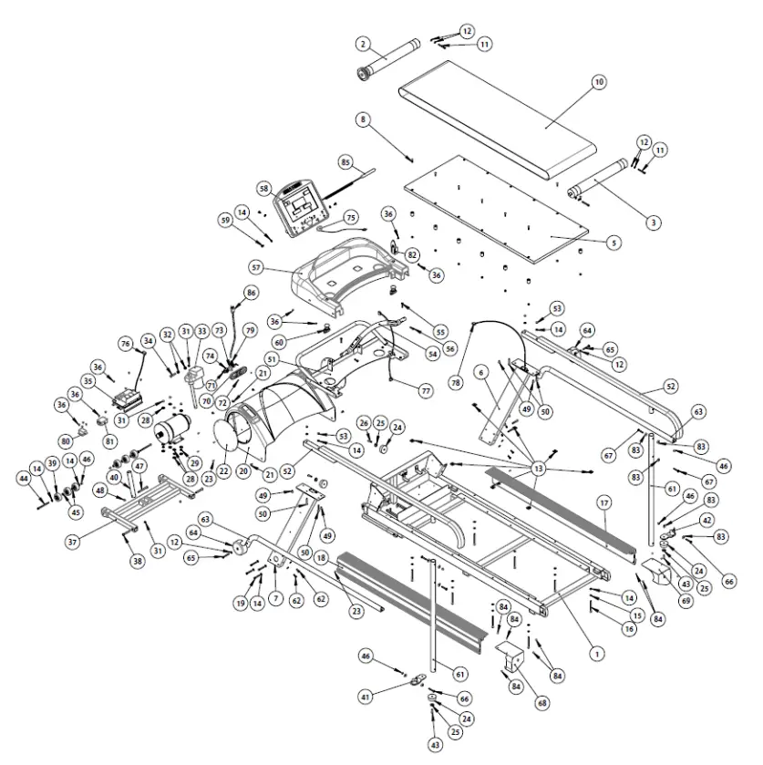
Parts List
| NO. | Description | Qty | NO. | Description | Qty |
| 001 | Main Frame | 1 | 044 | Mushroom Head Hexagonal Bolt M8*115L | 2 |
| 002 | Front Roller | 1 | 045 | Washer 8*18*2T | 4 |
| 003 | Rear Roller | 1 | 046 | Nylon Nut M8 | 6 |
| 004 | Suspension | 12 | 047 | Mushroom Head Hexagonal Bolt M8*115L | 1 |
| 005 | Running Deck | 1 | 048 | Nylon Nut M10*7L | 1 |
| 006 | Upright Pole(R) | 1 | 049 | Hexagonal Bolt M8*16L | 4 |
| 007 | Upright Pole(L) | 1 | 050 | Hexagonal Bolt M8*55L | 4 |
| 008 | Cross Screw M8*30L | 12 | 051 | Computer Rack | 1 |
| 009 | Nut M8 | 12 | 052 | Hand Pole – Long type | 2 |
| 010 | Running Belt with logo | 1 | 053 | Nylon Nut M8 | 4 |
| 011 | Mushroom Head Hexagonal Bolt M8*65L | 3 | 054 | Heart Rate Handle Bar | 1 |
| 012 | Washer 8*16*1.2T | 8 | 055 | Hexagonal Bolt M8*35L | 2 |
| 013 | 25 tapping Iron plates | 8 | 056 | Hexagonal Bolt M8*25L | 2 |
| 014 | Washer 8*18*1.5T | 32 | 057 | Computer Rack Cover | 1 |
| 015 | Spring Washer M8 | 8 | 058 | Console | 1 |
| 016 | Mushroom Head Hexagonal Bolt M8*100L | 8 | 059 | Mushroom Head Hexagonal Bolt M8*16L | 4 |
| 017 | Side Rail(R) | 1 | 060 | Emergency Stop Button | 2 |
| 018 | Side Rail(L) | 1 | 061 | Handle Support Tube – Long type | 2 |
| 019 | Mushroom Hexagonal Bolt M8*50L | 8 | 062 | Mushroom Head Hexagonal Bolt M8*20L | 4 |
| 020 | Motor Cover | 1 | 063 | Lower Hand Pole | 2 |
| 021 | Cross Screw M6*15L | 5 | 064 | Side handle Bar Cover | 2 |
| 022 | Acrylic adjust | 2 | 065 | Mushroom Head Hexagonal Bolt M8*60L | 2 |
| 023 | Metal screws TP4*16L | 10 | 066 | Mushroom Head Hexagonal Bolt M8*55L | 2 |
| 024 | Concave Buffer | 4 | 067 | Mushroom Head Hexagonal Bolt M8*50L | 4 |
| 025 | Washer 8*28*2T | 4 | 068 | Dipping Iron Cover(L) | 2 |
| 026 | Mushroom Head Hexagonal Bolt M8*30L | 2 | 069 | Dipping Iron Cover(R) | 2 |
| 027 | Clips | 5 | 070 | Power Set | 1 |
| 028 | Washer 10*25*2T | 12 | 071 | Cross Screw M5*25L | 2 |
| 029 | Washer 10*18*2.5T | 4 | 072 | Nylon Nut M5 | 2 |
| 030 | AC Servo Motor | 1 | 073 | 15A Circuit Breaker | 1 |
| 031 | Nylon Nut M10*7L | 7 | 074 | ON/OFF Light Switch – large | 1 |
| 032 | Motor cushion plug | 2 | 075 | Safety Key | 1 |
| 033 | Incline Motor | 1 | 076 | Lower Control Wire | 1 |
| 034 | Hexagonal Bolt M10*50L | 1 | 077 | Upper Control Wire | 1 |
| 035 | Lower control board | 1 | 078 | Middle Control Wire | 1 |
| 036 | Cross Screw M5*10L | 14 | 079 | Wire Holder | 1 |
| 037 | Frame Tubing Set | 1 | 080 | Inductor | 1 |
| 038 | Hexagonal Bolt M10*67L | 2 | 081 | Filter | 1 |
| 039 | PVC Roller | 6 | 082 | Fixed Holder | 1 |
| 040 | Incline Motor Tube | 1 | 083 | Washer 8*25*1.5T | 10 |
| 041 | Handle Support Base(L) | 1 | 084 | Metal screws TP4*12L | 12 |
| 042 | Handle Support Base(R) | 1 | 085 | Control Wire | 1 |
| 043 | Mushroom Head Hexagonal Bolt M8*25L | 2 | 086 | Plug | 1 |
Pair your PhysioMill with the PhysioGait Dynamic Unweighting System!
CUSTOMER SUPPORT
Over Ground or with a Treadmill!
www.PhysioGait.com