VEICHI BU30 series Brake Unit
Preface
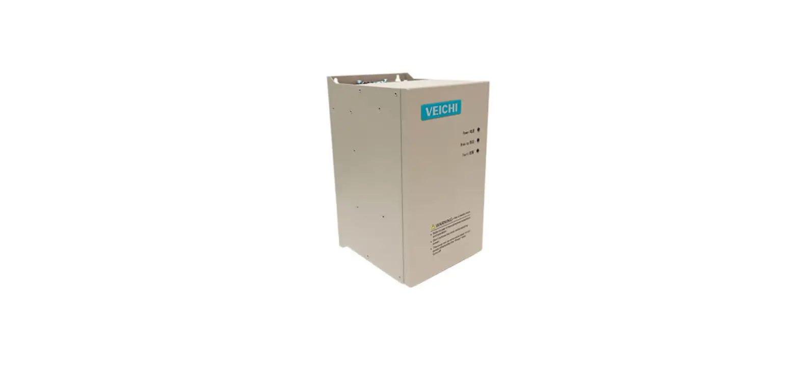
Thank you for choosing BU30 series energy braking unit. BU30 series adopts advanced power electronics technology and high performance MCU controller, combined with a new generation of IGBT power devices, a high performance braking products. This series of products can be applied to elevators, cranes, hoists, centrifuges, oilfield pumping machines and other occasions. Its products can release the electrical energy generated by the motor in the braking process through the power resistor (braking resistor) to produce enough braking torque to ensure the normal operation of the inverter and other equipment. This manual provides matters such as product installation and assembly lines, parameter setting and troubleshooting. To ensure proper installation and operation of this product and to take advantage of its superior performance, please read this manual in detail before use. This manual is a complimentary accessory, please keep it in a safe place and give it to the user of this machine. We are always striving for continuous improvement of our products, so the information about this series is subject to change without notice. We apologize for any inconvenience this may cause.
Security Information
Purchase Inspection
- Whether the specifications and models of the products match the ordered products.
- Our products have undergone strict testing and quality inspection before leaving the factory, please check whether there is a certificate of conformity, product manual and warranty card.
- Check if there is any damage inside the machine. If there is obvious damage, please do not operate and use the machine and contact the distributor or our company in time to avoid accidents.
Safety and wiring considerations
- Wiring operations must be performed by professionally qualified personnel, otherwise there is a risk of electric shock.
- When installing and wiring, the brake unit and other equipment such as inverters connected to it must be disconnected and wait for more than 10 minutes to confirm that the power stored in the capacitors of each related equipment is discharged before operating to ensure safety.
- The ground terminal of the brake unit must be grounded safely and securely, otherwise the equipment cannot work properly or there is a risk of electric shock.
- Once energized, the internal parts of the brake unit carry a dangerously high voltage and direct human contact should be avoided, otherwise it will endanger lives.
Attention
- The positive and negative terminals of the DC bus of the brake unit should not be reversed, otherwise it may not work or even cause damage to the equipment itself and related equipment, and there is a fire hazard.
- The brake unit should be installed in a well-ventilated area, otherwise the equipment may not work properly or may be damaged.
- Avoid dropping screws, gaskets and other metal objects inside the brake unit, as this may cause damage to the equipment. Make sure the case box cover is closed during use.
- Frequency converter, braking unit, braking resistance between the cable connection can not exceed 10 meters, please use shielded wire parallel signal line, the line length does not exceed 0.5 meters.
Product Introduction
Name plate and model description
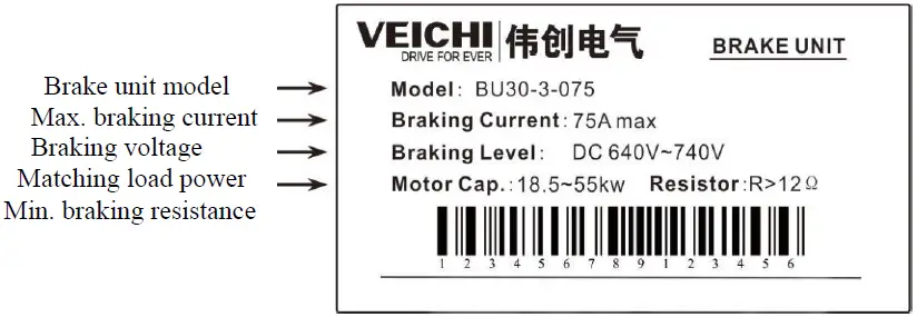
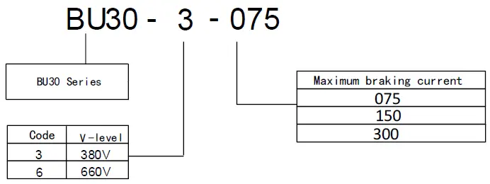
Model Description
Brake unit output specifications
The following table shows the recommended selection table for 380V and 660V machines. Type specification of energy consumption brake unit
| Brake Unit Model | Minimum resistance | Peak braking current | Adaptable inverter power | |
| light load | Heavy load | |||
| BU30-3-075 | 12Ω | 75A | 55~75KW | 22~45KW |
| BU30-3-100 | 9Ω | 100A | 90~132KW | 55~75KW |
| BU30-3-150 | 6.2Ω | 150A | 132~160KW | 90~110KW |
| BU30-3-300 | 3Ω | 300A | 185~250KW | 132~160KW |
| BU30-6-075 | 18Ω | 75A | 55KW~110KW | 22~55KW |
| BU30-6-100 | 14Ω | 100A | 132~160KW | 75~110KW |
Note:
Minimum resistance: is the minimum value of braking resistance allowed to be connected to the braking unit.The actual braking resistor used must be selected according to the capacity of the equipment and the required braking torque, and not less than the minimum resistance va lue of the braking unit.
Technical Specifications
| Project | Specification T3 T6 | ||
| Power | Bus voltage | DC400V~DC900V | DC600V~DC1300V |
|
Control | Braking method | Automatic voltage tracking method | |
| Reflection time | Within 1ms with multiple noise filtering algorithms | ||
| Operation voltage | The braking voltage point can be set arbitrarily, see section 4.1 for the setting method, and the maximum deviation of its value is ±10V | ||
| Hysteresis Loop Voltage | Adjustable parameters, see section 4.1 for setting method | ||
| Protection function | Overload, short circuit, over temperature | ||
| Parallel input | Automatic recognition of parallel drive, no parameter setting | ||
| Parallel output | |||
|
Display with Settings | Status indication | Power indication, working indication and fault indication | |
| Operation monitoring | Bus voltage can be viewed from the keypad | ||
| Operation voltage setting | BU30 products can be set by keypad, the keypad can be used with our inverter keypad or optional. | ||
|
Environ ment | Installation site | Indoor, not more than 1000 meters above sea level (for every 1000 meters above sea level, 10% reduction must be used), no direct sunlight, no conductive dust and corrosive gas | |
| Environment temperature | -10~40℃,Good ventilation | ||
| Environmenta l humidity | Below 90% RH (no condensation) | ||
| Vibration degree | 0.5g or less | ||
| Installation method | wall resignation | ||
| Cooling method | Air-cooled | ||
Installation
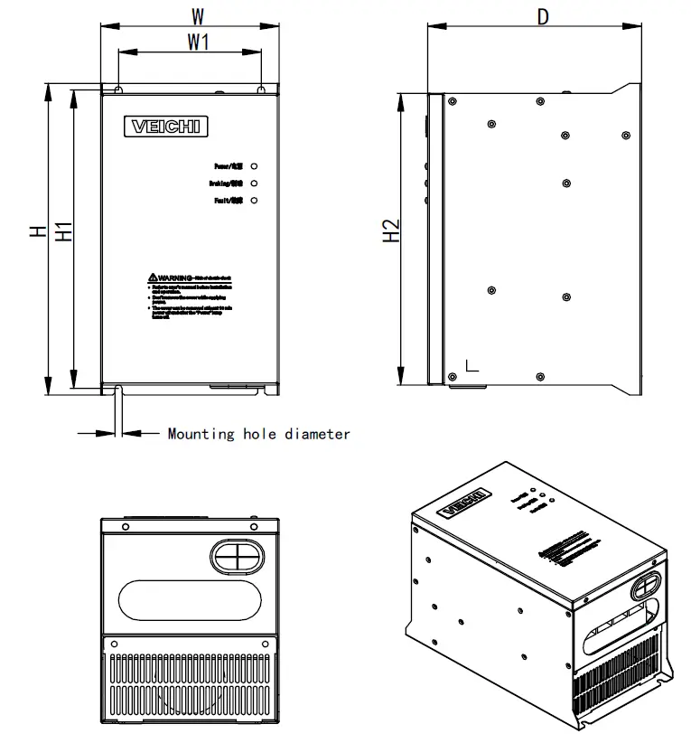
Mechanical mountin dimensions(Unit:mm)
|
| |||||||
| Brake Unit Model | Dimension | Installation hole position | Apertur e | ||||
| W | H | D | H2 | W1 | H1 | ||
| BU30-3-075 | 150 | 274 | 180 | 256 | 120 | 262 | Ф6 |
| BU30-3-100 | |||||||
| BU30-3-150 | |||||||
| BU30-3-300 | 190 | 355 | 210 | 335 | 130 | 343 | Ф6 |
| BU30-6-075 | 180 | 320 | 205 | 300 | 130 | 308 | Ф6 |
| BU30-6-100 | |||||||
Definition of terminal arrangement
Terminal arrangement order:
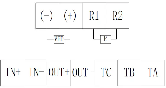
| Terminal Sign | Terminal name | Terminal Function Definition |
| (-) | DC power input terminal | (-)Inverter bus negative |
| (+) | (+)Inverter bus positive | |
| R1 | Brake resistor terminal | Separately connected to the braking resistor terminal |
| R2 | ||
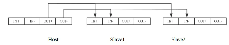
| IN+ | Parallel drive input | Connect to host OUT+ |
| IN- | Connect to host OUT- | |
| OUT+ | Parallel drive output | Connect to slave IN+ |
| OUT- | Connect to slave IN- | |
| TC-TB | Fault output relay | Relay normally closed contact |
| TC-TA | Relay normally open contact |
Wiring diagram
- Single machine wiring diagram

- Wiring diagram for parallel operation of multiple machines

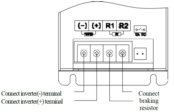
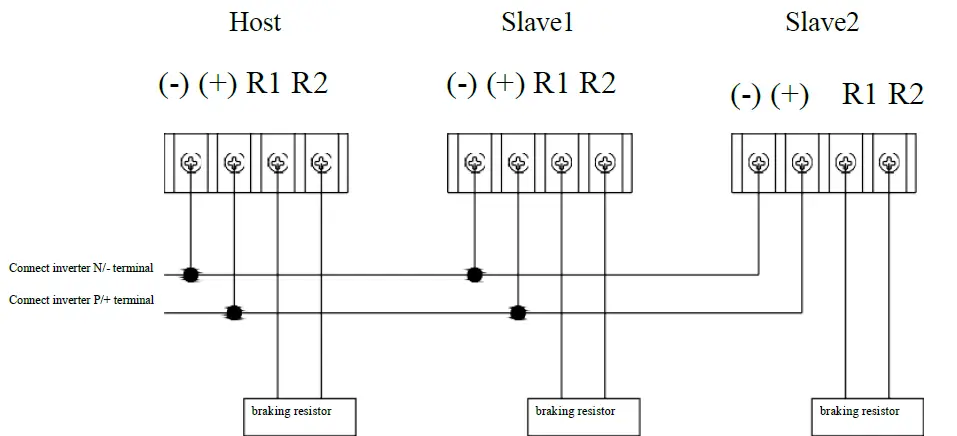
Main circuit wiring diagram
Note:
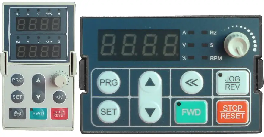
The BU30 is able to adapt automatically when the brake unit is connected in parallel. In the few cases where automatic adaptation is not possible, it is necessary to adjust F4.00 (Braking Voltage) with the keyboard, For example, if the + – bus voltages of two units do not match, then we can adjust the braking voltage of either brake unit to accommodate. The keypad of AC70T can be used on BU30 to adjust the keypad of the brake unit as follows:
Keyboard Function
Basic parameter setting
| NO. | Function code name | Setting value range and definition | Factory setting | Properties | ||
| T3 | T6 | T3 | T6 | |||
| F4.00 | Braking Voltage | 640V-740V | 1070V-1170V | 680V | 1120V | 〇 |
| F4.01 | Hysteresis Loop Voltage | 1V-40V | 5V | 〇 | ||
| F4.02 | Fan start point | 50℃-75℃ | 50℃ | 〇 | ||
| F4.03 | Overheat protection point | 75℃-85℃ | 75℃ | |||
|
F4.04 |
Fault alarm selection | 0- Select OL valid 2- Selecting OC valid 3- OL OC is valid at the same time 55- Turn off all fault alarms | 2 | |||
| F4.05 | Reserved | 5 – 9999 | 5 | |||
| F4.06 | Fault output logic selection | 0- Positive logic 1- Inverse logic | 0 | |||
| F4.07 | Previous fault type | |||||
| F4.08 | First two failure types | |||
| F4.09 | Fan switch selection | 0- Start point on 1- Power up and turn on | 0 | |
| F4.10 | Restore factory parameters | 0- Forbidden by default 1- Restore factory values | 0 | |
| F4.11 | Fault self-recovery times | 0 – 3 | 0 | |
| F4.12 | Fault self-recovery waiting time | 0.1 – 20.0s | 1.0s |
Indicates that the parameter cannot be changed while the drive is running.
Monitoring parameters
| N0. | Function code name | Setting value range and definition |
| C-00 | Temperature | 0.1℃ |
| C-01 | Voltage | 1V |
| C-02 | Current | 0.1A |
| C-03 | Software Version |
Fault Information
| Keyboard display | Fault Type | Possible failure causes | Troubleshooting |
|
E.oL1 |
Brake overload | ● Brake resistor short circuit or brake resistor connection wire short circuit; ● Abrupt or abnormal feedbacks; ● The power of the brake unit is low; ● The resistance value of the braking resistor is small; | ● Check whether the brake resistor or connection is normal, press the “RESET” key to reset or reapply power. ● Checking for load variations and eliminating them. ● Selection of a brake unit with one higher power level. ● Selection of the appropriate resistance value of the braking resistor. |
| E.oC1 | Brake overcurrent | ||
|
E.oH2 |
Brake overheating | ● High ambient temperature; ● Blocked air duct; ● Loose fan connection inserts. ● Fan damage; ● Temperature detection circuit failure; ● The power of the brake unit is low; | ● Lowering the ambient temperature. ● Unclogging of air ducts; ● Checking and reconnecting ● Replacement of the fan of the same type. ● Seeking technical support from manufacturers. ● Seeking technical support from manufacturers. |
|
E.HAL |
Abnormal current detection |
● Fault in the current detection circuit. |
● Seeking technical support from manufacturers. |
Note:
- E.oL1 Alarm indicator flashes once at 2-second intervals.
- E.oc1 alarm indicator flashes 3 times at 2-second intervals.
- E.Oh2 alarm indicator flashes 5 times at 2-second intervals.
- E.HAL alarm indicator is always on.
- When setting parameters, you need to disassemble the brake unit panel and insert the standard keyboard of our inverter into the DB9 keyboard port of the brake unit PCB to set parameters.
Braking Resistor Selection
The braking resistor selection is based on the power generated by the motor in the actual application. It is related to the system inertia, deceleration time, bit energy load, etc. It needs to be selected by the customer according to the actual situation. The larger the inertia of the system, the shorter the deceleration time and the more frequent the braking, the larger the power of the braking resistor required and the smaller the resistance value.
Selection of resistance value of braking resistor
- It can be based on the formula:PD = 2/R
- The formula U – the selected brake voltage grade
- PD-Braking power
Braking resistor power selection
The braking resistor needs to be derated by 70% when used. According to the formula.PR=PD*KC/0.7
- In the formula PR – braking resistor power
- PD-Braking power
- KC-Braking frequency
The braking frequency of common load types takes the following values for Kc in general
- Elevator Ke=10-15%
- Lowering height of more than 100m crane Kc=2040%
- Oilfield head knocker Ke=1020%
- Unwinding and winding Ke=50~60%
- Centrifuge Kc=5~20%
- Occasional braking of loads Ke=5%
- Other Kc=10%
The following table describes the braking resistor resistance, resistance power for the recommended value, if you need to use in the large inertia, long time frequent braking and special occasions, please provide the formula calculation and the selected inverter specifications, the rated parameters of the braking unit, appropriate adjustment of the braking resistor resistance and resistance power
| Three-phase 380V level | ||||
|
Motor power (kW) | Resistance value (Ω) | Ordinary inertia resistance power(W) | Large inertia recommended resistive power | Braking torque (%) |
| 22 kW | 21Ω | 2,200W | 2,200W*2 | 150% |
| 30 kW | 16Ω | 3,000W | 3,000W*2 | 150% |
| 37 kW | 13Ω | 3,700W | 3,700W*2 | 150% |
| 45 kW | 11Ω | 4,500W | 4,500W*2 | 150% |
| 55 kW | 8.2Ω | 5,500W | 5,500W*2 | 150% |
| 75 kW | 6.0Ω | 7,500W | 7,500W*2 | 150% |
| 90 kW | 5.0Ω | 9,300W | 9,300W*2 | 150% |
| 110 kW | 4.1Ω | 11,000W | 11,000W*2 | 150% |
| 132 kW | 3.4Ω | 13,000W | 13,000W*2 | 150% |
| 160 kW | 2.8Ω | 15,000W | 15,000W*2 | 150% |
| 185 kW | 2.5Ω | 17,000W | 17,000W*2 | 150% |
| 200 kW | 2.3Ω | 18,500W | 18,500W*2 | 150% |
| 220 kW | 2.1Ω | 20,000W | 20,000W*2 | 150% |
| 250 kW | 1.8Ω | 22,500W | 22,500W*2 | 150% |
| 280 kW | 1.6Ω | 25,500W | 25,500W*2 | 150% |
| 315 kW | 1.4Ω | 30,000W | 30,000W*2 | 150% |
| 355 kW | 1.3Ω | 33,000W | 33,000W*2 | 150% |
| 400 kW | 1.1Ω | 42,000W | 42,000W*2 | 150% |
| 450 kW | 1Ω | 42,000W | 42,000W*2 | 150% |
| 500 kW | 1Ω | 42,000W | 42,000W*2 | 150% |
| 560 kW | 1Ω | 50,000W | 50,000W*2 | 150% |


