HOFTRONIC 5438127 Remote Control LED Cali Highbay
SPECIFICATIONS
- POWER SUPPLY 2x AAA batteries, alkaline preferred (not included)
- CARRYING CASE Carrying case included
- RANGEUp to 15m (50ft)
- OPERATING TEMPERATURE 0°C-50°C (32°F-122°F)
- DIMENSIONS 123x70x20.3 mm (4.84”x2.76”x0.8”)
WARNING!
Remove the batteries from the remote if the remote will not be used for extended periods (30 days).
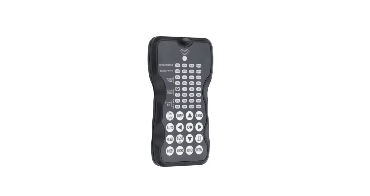
OVERVIEW
The remote control Wireless IR Configuration Tool is a handheld tool for the remote configuration of IR-enabled fixture-integrated sensors. The tool enables the device to modify via pushbutton without ladders or tools, and stores up to four sensor parameter modes to speed the configuration of multiple sensors.
The remote control sends the sensor setting at a mounting height of up to 50 feet. The device can display previously established sensor parameters, copy parameters and send new parameters or store parameter profiles. For projects where identical settings may be desired across a large number of areas or spaces, this capability provides a streamlined method of configuration. Settings can be copied throughout a site or in different sites.
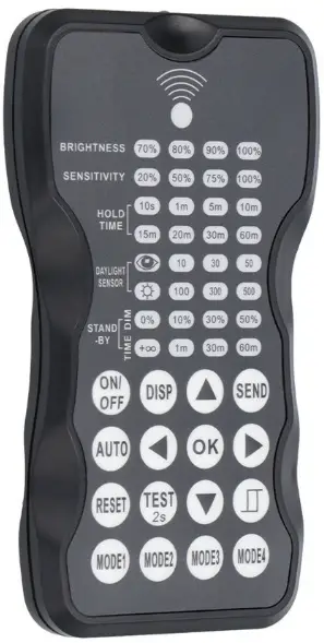
LED INDICATORS
| LED | DESCRIPTION | LED | DESCRIPTION |
| BRIGHTNESS | High end trim turning function (to set the output level of connected lighting during operation | To select the current surrounding lux value as the daylight threshold. This feature enables the fixture to function well in any real application circumstances | |
| SENSITIVITY | To set the occupancy sensing sensitivity of the sensor |
| The daylight sensor stops working and all motion detected could turn on the lighting fixture, no matter how bright the natural light is |
|
HOLD TIME | The time that the sensor will turn off (if you choose stand by level is 0) or dim the light to a low level after the area is vacated |
STAND-BY DIM | To set the output level of connected lighting during vacancy. The sensor will regulate the lighting output at the set level. Setting the stand by dim level at 0 means light full off during vacancy |
| DAYLIGHT SENSOR | To represent various thresholds of natural light level for the sensor | STAND-BY TIME | To represents the time that the sensor will keep the light at low dim level after the hold time elapsed |
| BUTTON | DESCRIPTION | BUTTON | DESCRIPTION |
| Press the ON/OFF button, to turn the light on or off. | Press the AUTO button to activate the optional motion sensor. | ||
| Display the current settings with the LED indicators. |
Press the TEST button to test the sensitivity of the motion sensor. After testing press the AUTO button to return to normal operation. | ||
| Press the RESET button, all settings revert to those indicated by the dip switch on the light. | |||
| Navigate up and down to choose the selected parameters. | Navigate left and right to choose the selected parameters. | ||
| Confirm the selected parameters on the remote control. | |||
| Press SEND button to upload the current parameters to the motion sensor. The LED light will blink as confirmation. | Press this button to open or close the smart daylight sensor. | ||
 | 4 scene modes with preset parameters which are available to be changed and saved in modes. |
SETTING
The SETTING Content contains all available settings and parameters for remote sensors. lt allows you to change the available control, parameters, and operation of the sensor from factory default or current parameters.
CHANGE SETTINGS OF SENSOR(S)
- Press
 the button, the remote control LEDs will show the latest parameters you set.
NOTE: if you push the button before, you must push
 the button to unlock the sensor.
 - Press
 or
or enter the setting condition, and the parameter LEDs of the remote control will flash to be selected, navigate to the desired setting by pressing
 to select the new parameters.
 - Press ok to confirm all settings and savings.
- Aim at the target sensor and press to upload the new parameter, the led light which the sensor connects will be on/off as confirmed.
- NOTE: the setting works key step is by Pushing or, entering in the set condition.
- NOTE: the led light that the sensor connects will be on/off after getting the new parameter as confirmed.
- NOTE: if you press the button, the remote led indicators will show the latest parameters which were sent.
- NOTE: the setting works key step is by Pushing
CHANGE SETTINGS OF SENSOR(S) WITH SMART PHOTOCELL SENSOR OPEN
- Press, the remote led indicators will show the latest parameters.
- Press or enter the setting condition, and the parameter LED indicators of the remote control will flash to be selected.
- Press
 , 2 LED indicators will flash in daylight sensor settings, select daylight
 setpoint to light automatically, and select daylight
 as a setpoint to light off automatically.
 - Press
 to confirm all settings and save.
 - Aim at the target sensor and press
 to upload the new parameter. The LED light which the sensor connects will go on/off.
NOTE:![]() is disabled by default.
is disabled by default.
- Open or close the smart daylight sensor by pushing when the remote control is in setting condition.
- When the smart daylight sensor opens, 2 Led indicators flash in the daylight sensor setting. select daylight as a setpoint to light on Automatically, and select daylight setpoint to light off automatically. When the smart daylight sensor closes, 1 Led indicator is flashed in the daylight sensor setting for choosing the daylight sensor threshold.
- When the smart daylight sensor opens, the standby time is only

- A smart daylight sensor takes place of a normal photocell sensor and works independently.
- See Daylight Sensor Function.
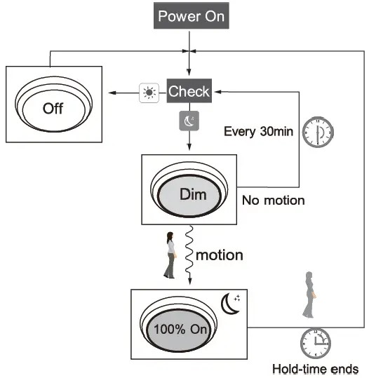
CORRIDOR FUNCTION
This function is inside the motion sensor to achieve tri-level control. for some areas which require a light change notice before switch-off. The sensor offers 3 levels of light: 100%–>dimmed light (natural light is insufficient)–>off; and 2 periods of selectable waiting time: motion hold-time and stand-by period; Selectable daylight threshold and freedom of detection area. 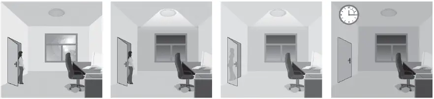
- With sufficient natural light, the light does not switch on when presence is detected.
- With insufficient natural light, the sensor switches on the light automatically when presence is detected.
- After hold-time, the light dims to stand-by level if the surrounding natural light is below the daylight threshold.
- The light switches off automatically after the stand-by period elapses.
DAYLIGHT SENSOR FUNCTION
Open the daylight sensor by pushing![]() when the remote control is in setting condition.
when the remote control is in setting condition. 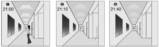
- The light switches on at 100% when there is movement detected.
- The light dims to a stand-by level after the hold time.
- The light remains at a dimming level at night.

- When the natural light level exceeds the setpoint off to light, the light will turn off even when the space is occupied.
- The light automatically turns on at 10% when natural light is insufficient (no motion).

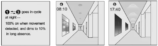
Settings on this demonstration:
- Hold-time: 30min
- Stand-by Dim: 10%
- Setpoint to light
- on: 50lux Stand-by period: +
- Setpoint to light
- off: 300lux (when the smart photocell sensor opens, the standby time is only + )
CORRIDOR FUNCTION VS DAYLIGHT SENSOR FUNCTION
- ln corridor function, turn on the light MUST by natural light level lower daylight sensor setting and Occupancy. In the smart daylight sensor function, turn on the light by natural light level lower daylight setpoint to light on even if vacancy.
- ln corridor function, turn off light by stand-by time finish if vacancy. In the smart daylight sensor function, turn off the light by natural light level higher than the daylight setpoint to light off even if occupancy.
- ln smart daylight sensor function, natural light level lighter/lower than daylight setpoint to light off/on MUST keep at least 1 minute, that will turn off/on the light automatically.
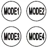
ABOUT RESET AND MODE (1,2,3,4)
The remote control comes with 4 Scene MODES which does not default. You may make desired parameters and save them as the new MODE(1,2,3,4) to configure the installed sensors.
RESET: all settings go back to the settings of the DIP Switch in the sensor.
| Application | Scene options | Brightness | Detection area | Hold time | Stand-by time | Stand-by dim level | Daylight sensor |
| Indoor | Mode 1 | 100% | 75% | 5min | 30min | 30% | |
| Indoor | Mode 2 | 100% | 75% | 1min | 30% | ||
| Indoor | Mode 3 | 100% | 75% | 5min | 30min | 30% | 30LUX |
| Outdoor | Mode 4 | 100% | 75% | 1min | 30% | (30LUX/300LUX) |
CHANGE THE MODES:
- Press
 the button, the remote control Led indicators to show existing parameters.
 - Press to select the new parameters.
- Press to confirm all parameters and save in the mode.
 the button, the remote control Led indicators to show existing parameters.
UPLOAD
The upload function allows you to configure the sensor with all parameters in one operation. You may select CURRENT SETTING parameters or the MODE for uploading. Current setting parameters or the MODE are displayed in the Remote control.
Upload the current parameters to sensor(s), and duplicate the sensor parameters from one to another
- Press the button or press, all parameters displayed on the Remote control. Note: check if all parameters are correct, if not, change them.
- Aim at the sensor and press the button, the light that the sensor connects will be on/off as confirmed.
Note: if other sensors need the same parameters, just aim at the sensor and press![]() the button.
the button.
INTENDED USE/APPLICATION
Product designed for use in households and for other similar general applications.
MOUNTING
Technical changes reserved. Read the manual before mounting. Mounting should be performed by an appropriately qualified person. Any activities to be done with disconnected power supply. Exercise particular caution. The product has a protective contact/terminal. Failure to connect the protective lead may lead to electric shock. Mounting diagram: see pictures. Check for proper mechanical fastening and connection to electrical power prior to first use. The product can be connected to a supply network that meets energy quality standards as prescribed by law. To maintain the proper IP protection level, the right diameter of the power cable should be selected for the cable gland used in the product.
FUNCTIONAL CHARACTERISTICS
The product can be used indoors only.
USAGE GUIDELINES/MAINTENANCE
Any maintenance work must be performed when the power supply is cut off and the product has cooled down. Clean only with soft and dry clothes. Do not use chemical detergents. Do not cover the product. Ensure free air access. The product may heat up to a higher temperature. The product can only be supplied by rated voltage or voltage within the range provided. It’s forbidden to use the product with a damaged protective cover. The product must not be used in unfavorable conditions, e.g. dust, water, moisture, vibrations, explosive air atmosphere, fumes, or chemical fumes, etc. Non-demountable product. Not suitable for independent repairs.
ENVIRONMENTAL PROTECTION
Keep your environment clean. Segregation of post-packaging waste is recommended. This labeling indicates the requirement to selectively collect waste electronic and electrical equipment. Products labeled in this way must not be disposed of in the same way as other waste under the threat of a fine. These products may be harmful to the natural environment and health and require a special form of recycling/neutralizing. Products labeled in this way should be returned to a collection facility for waste electrical and electronic goods. Information on collection centers is provided by local authorities or sellers of such goods. Used items can also be returned to the seller when new product is purchased, in quantity no larger than the purchased item of the same type. The above rules regard the EU area. In the case of other countries, regulations in force in a given country must be applied. Contacting the distributor of our products in a given area is recommended.
COMMENTS/GUIDELINES
Failure to follow these instructions may result in e.g. fire, burns, electrical shock, physical injury, and other material and non-material damage. For more information about Hoftronic products visit www.hoftronic.com. Hoftronic shall not be responsible for any damage resulting from the failure to follow these instructions. Hoftronic reserves the right to make changes in the manual – the current version can be downloaded at www.hoftronic.com.
DECLARATION OF CONFORMITY
DOCUMENTATION
This product has been manufactured and supplied in compliance with all relevant regulations and directives applicable to all member states of the European Union. The product complies with all applicable regulations and rules in the country of sale.
Formal documentation such as the declaration of conformity, the safety data sheet, and the product test report is available upon request.
CE DECLARATION
The product complies with the following directives:
- LVD: 2014/35/EU
- EMC: 2014/30/EU
- RoHS: 2011/65/EU
The complete Declaration of Conformity Document (DOC) is available upon request.
Imported by
HOF Trading B.V.
Fahrenheitstraat 11, 6003 DC Weert , The Netherlands Made in P.R.C. www.hoftronic.com.


