SNS 1×1 Light Pods Installation Guide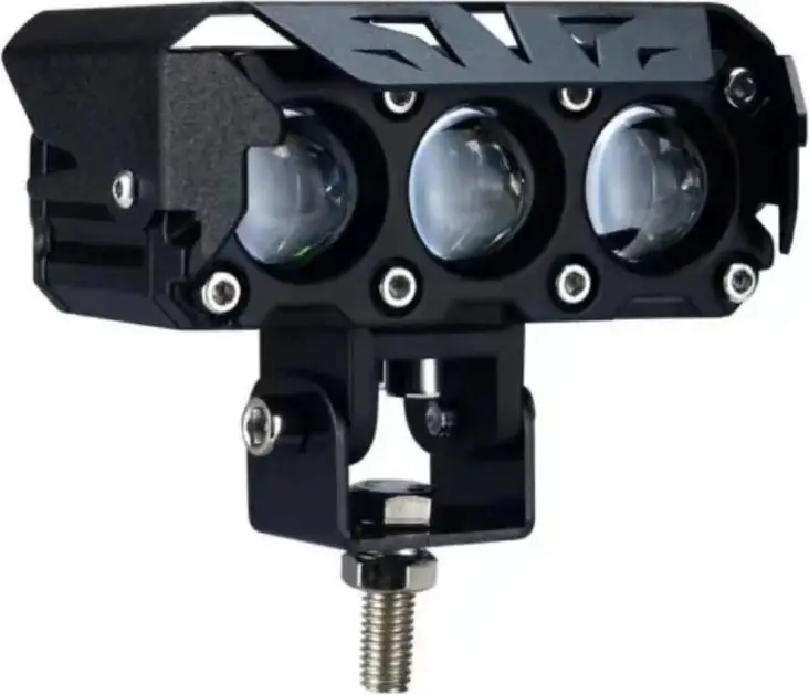
Safety
Care must be taken when handling the sharp items listed below such as the razor blades, cutters, sharp objects, and soldering irons.
Visual Icons
| Symbol | Definition | Description |
 | Inspect/Verify | The magnifying glass is used for inspection or verification to take place. |
 | Work Content | The hammer is used to identify a process step where building of the product takes place. |
| Safety Warning | The yellow hazard triangle is used to identify process steps that involve potential safety hazards. | |
| | Safety Action | The red stop sign is used to identify process steps where a safety action must be performed before proceeding with the next operation. |
Consumables and Equipment List
| Consumables | Equipment |
| Zip Ties | Wire Cutter |
| Electrical Tape | Solder Iron |
| Solder | Multimeter |
| Barrell Connector | Crimper |
| Solder/Shrink Wrap Connector | Open Combination Wrench |
Procedure Detail
| 1. Unboxing the Package Content | ||
| Step | Instruction | Visual Aid (for reference only) |
| 1. | Open the flap of the box and remove all the parts from the box content. Layout all the parts to prepare for installation. | 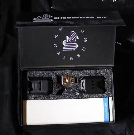 |
| 2. | Parts in the content includes the following:1. 1 set of lights2. 1 set of mounting brackets with bolt, lock washer, and nut.3. 4 mounting hex bolts for bracket mounting with washers.4. 1 wiring flash kit module5. 1 On/OFF button with Strobe mode6. 1 Allen Key | 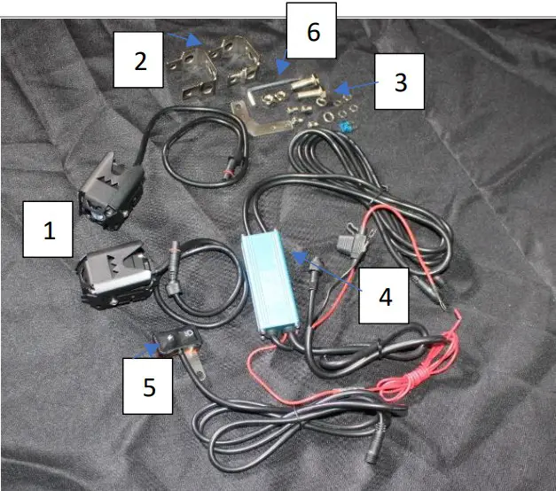 |
| 2. Assembly of SNS Light Pods with Strobe Controller | ||
| Step | Instruction | Visual Aid (for reference only) |
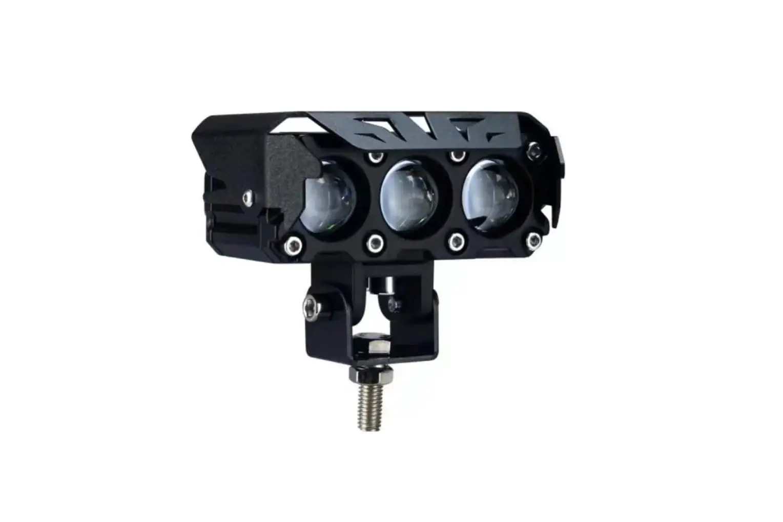
| 1. | Assemble Light Pod as shown in picture to the right for the 1×1 PODs. | 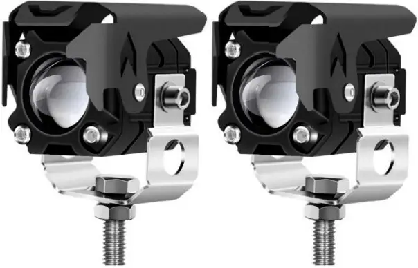 |
| 2. | Assemble Light Pod as shown in picture to the right for the 1×2 PODs. | 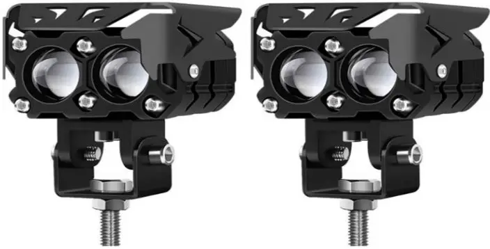 |
| 3. | Assemble Light Pod as shown in picture to the right for the 1×3 PODs. | 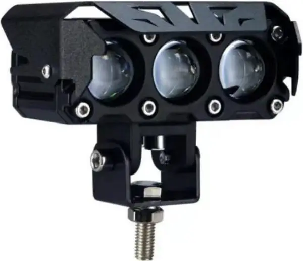 |
| 4. | Do not attempt to use force to push and mate connector together. Doing so will damage the 3-pin prong that are 120 degrees apart. Inspect circular connector for key alignment position and make sure all pins are straight. | 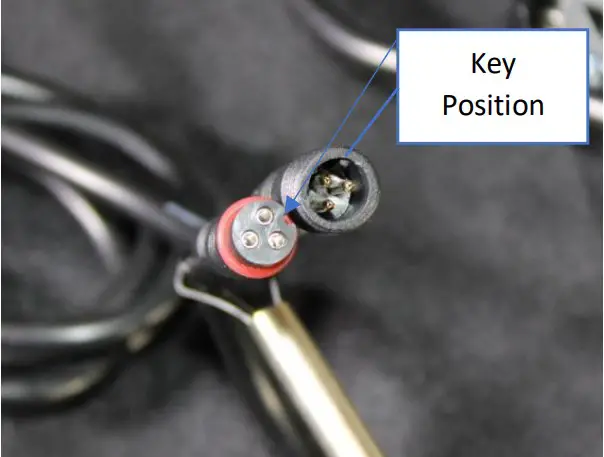 |
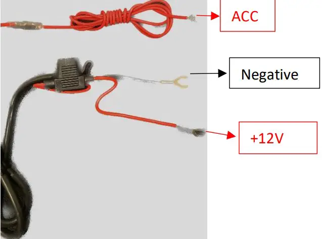
| 5. | The blue box is the strobe unit controller. Connect the switch to the strobe unit controller and connect the Power +12VDC to the RED wire with the inline fuse and the Ground / Negative to the BLACK wire. The red wire with the terminated barrel connector is the ACC wire. Connect this wire to an ignition ON so that the lights could be turn on when the car is at the ON position. If you would like to bypass the ACC and have anytime ON/OFF while the vehicle is off.Connect the ACC to a +12volts source. |
|
| 6. | To assemble the light pod, use the circular connector of the light pod and attach them to the dual circular connector coming out of the strobe unit as show in the picture to the right. Ensure that both arrows are aligned. | 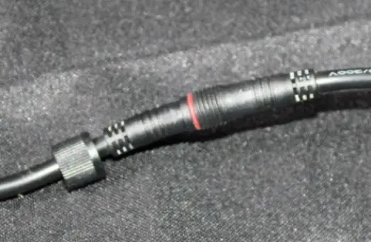 |
| 7. | Twist the circular lock to keep both connectors in place and waterproof. | 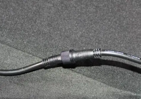 |
| 8. | To Turn ON the light, depress the light switch on the left hand of the switch. To toggle between clear and amber, depress the light switch. To Strobe the lights, depress the lightning symbol for synchronize strobe. For alternating strobe, depress the lightnign button once more. To turn OFF the light pods, Press and HOLD the light switch button for 5seconds. | 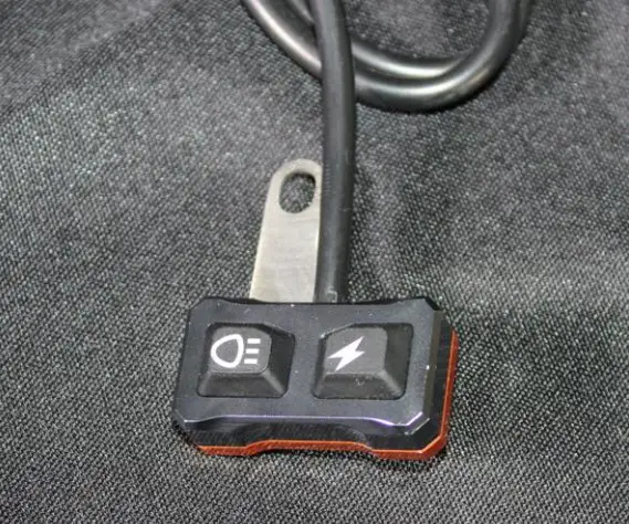 |
| 3. Wiring PODS with Switch Panel Configuration | ||
| Step | Instruction | Visual Aid (for reference only) |
| 1 | To wire the light pod into a switch panel. The following wire when wired as shown in picture will light the white or yellow light. | 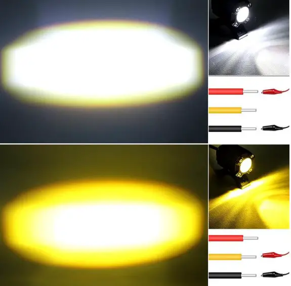 |
| 2. | Splice the strobe controller wire at the following location to have a full 6 feet wire length. Cut the black outer jacket to expose the RED, YELLOW, and Black wire. If you would like to wire both White and Amber to turn ON with a single switch. Ensure that the switch panel could handle the current draw load. 1×1 2 pods are 4 Amp Draw minimum 1×2 2 pods are 6 Amp Draw minimum 1×3 2 pods are 8 Amp Draw minimum | 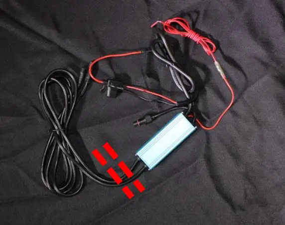 |


