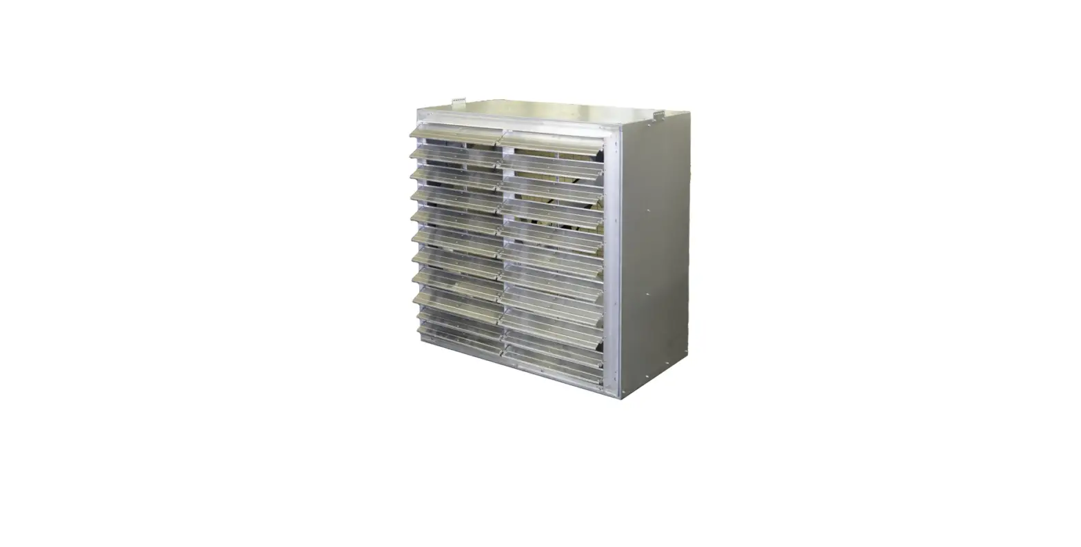
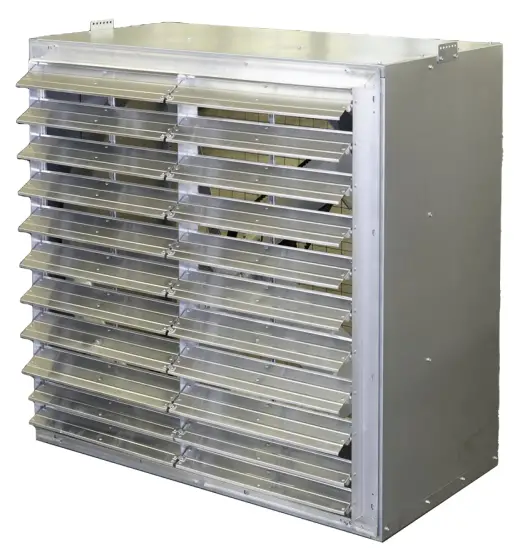
HESSAIRE 36D370S Cabinet Exhaust Fans
Model Numbers Covered:
36D370S, 36D370TS, 36DL750S, 36DL750TS, 36XL550S, 36XL750S, 36XL750TS, 42DL750S, 42DL750TS, 42XL750S, 42XL750TS, 42XL1125S, 42XL1125TS, 48XL750S, 48XL750TS, 48XL1125S, 48XL1125TS
Please read and save these instructions. Read carefully before attempting to assemble, install, operate or maintain the equipment described within this manual. Carefully follow all safety information.
Getting Started
Tools/Materials Needed:
- Drill/drill bits
- Saw
- Level
- Screwdriver(s)
- 5/16” nut driver
- Construction screws
- Caulk or sealant
Inspection:
After unpacking your fan, carefully inspect for any damage that may have occurred during transit. Inspect for loose, missing or damaged parts. If there is physical damage to any parts of the fan, a freight claim must be filed with the carrier. Check to assure that all bolts, screws and set screws are securely tightened and have not become loose during transit. Retighten as required. Rotate propeller by hand to assure it turns freely.
General Safety Instructions
Warning: Before installing or servicing, always lock out and tag power source. Do not rely on a switch as the only means of disconnecting power. Failure to disconnect power can result in fire, electrical shock or serious injury. Motor will restart without warning after thermal protector trips. Do not touch an operating motor as it may be hot enough to cause injury. Do not place any body parts or objects in fan or drive components while fan is connected to a power source.
Caution:
- Read and follow all instructions, cautions, dangers and warnings. Failure to do so could result in personal injury, death or property damage.
- Make sure the electrical power source conforms to the requirement of the fan(s) as well as local codes.
- Electrical connections, installation and maintenance must be done by qualified electrical personnel in accordance with all applicable codes and ordinances.
- Unit must be adequately grounded.
- To reduce the risk of fire or electrical shock, do not expose this fan to water.
- Do not touch electrically live components.
- Free rotation of the propeller is critical. It must not touch any part of the venturi or framework.
- Assure that all power cords do not come in contact with any sharp edges, hot surfaces or chemicals. Immediately replace any damaged cords.
- Before operating your new fan, ensure propeller is torqued properly and all fasteners, screens and shutters are securely in place.
OSHA-compliant guards must be in place when fan is installed within 7ft of the floor or working level.
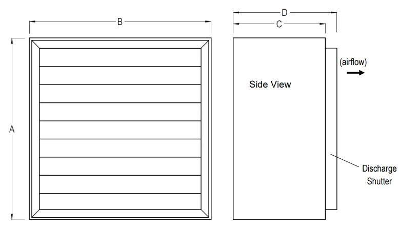
Specifications
| Model | Prop Dia. | Dimension (In.) | Rough-in Opening (In.) | Unit Weight (lbs) | ||||
| A | B | C | D | Height | Width | |||
| 36D370S | 36” | 40 1/8 | 40 1/8 | 14 | 16 | 40 3/4 | 40 3/4 | 110 |
| 36D370TS | 36” | 40 1/8 | 40 1/8 | 14 | 16 | 40 3/4 | 40 3/4 | 110 |
| 36DL750S | 36” | 40 1/8 | 40 1/8 | 24 | 26 | 40 3/4 | 40 3/4 | 130 |
| 36DL750TS | 36” | 40 1/8 | 40 1/8 | 24 | 26 | 40 3/4 | 40 3/4 | 130 |
| 36XL550S | 36” | 40 1/8 | 40 1/8 | 24 | 26 | 40 3/4 | 40 3/4 | 130 |
| 36XL750S | 36” | 40 1/8 | 40 1/8 | 24 | 26 | 40 3/4 | 40 3/4 | 155 |
| 36XL750TS | 36” | 40 1/8 | 40 1/8 | 24 | 26 | 40 3/4 | 40 3/4 | 155 |
| 42DL750S | 42″ | 46 1/8 | 46 1/8 | 24 | 26 | 47 | 47 | 150 |
| 42DL750TS | 42″ | 46 1/8 | 46 1/8 | 24 | 26 | 47 | 47 | 150 |
| 42XL750S | 42″ | 46 1/8 | 46 1/8 | 24 | 26 | 47 | 47 | 175 |
| 42XL750TS | 42″ | 46 1/8 | 46 1/8 | 24 | 26 | 47 | 47 | 175 |
| 42XL1125S | 42″ | 46 1/8 | 46 1/8 | 24 | 26 | 47 | 47 | 190 |
| 42XL1125TS | 42″ | 46 1/8 | 46 1/8 | 24 | 26 | 47 | 47 | 190 |
| 48XL750S | 48″ | 52 1/8 | 52 1/8 | 24 | 26 | 53 | 53 | 190 |
| 48XL750TS | 48″ | 52 1/8 | 52 1/8 | 24 | 26 | 53 | 53 | 190 |
| 48XL1125S | 48″ | 52 1/8 | 52 1/8 | 24 | 26 | 53 | 53 | 205 |
| 48XL1125TS | 48″ | 52 1/8 | 52 1/8 | 24 | 26 | 53 | 53 | 205 |
Fan Installation
- For framing dimensions, refer to rough-in opening height and width shown in the specifications above.
- Fan is designed to mount in wall with air discharging towards the outside. Center fan weight in opening.
- Position the fan in the wall with the discharge shutter facing to the outside of the building. Louvers hang down, closed completely.
- Ensure the fan is fastened securely in the opening to avoid excess “rattling” or vibration using proper fasteners. Fasteners not included.
- An aluminum or iron angle is recommended on sides/top/bottom of fan to attach fan to wall and help close rough-in gap around fan. Angle
- should attach to fan housing and wall opening frame to securely hold fan in place.
- Fan support bracing(wall brackets) should be used to properly support the portion of fan that hangs out of opening.
- Seal around fan to prevent air leakage.
- Refer to motor nameplate for wiring diagram.
Repair Parts Illustration
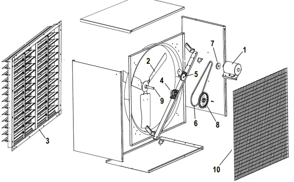
Belt Drive Fans
| No | Description | 36XL550S | 36XL750S | 36XL750TS |
| 1 | Motor | A550-4CE | A750-4CE | A750-4T |
| 2 | Prop | 9001565 | – | – |
| 3 | Shutter | SA36 | SA36 | SA36 |
| 4 | Bearings | UCP20516 LDK | UCP20516 LDK | UCP20516 LDK |
| 5 | Tensioner | BTI | BTI | BTI |
| 6 | Belt | AX51 | – | – |
| 7 | Motor Sheave | AK3958 | – | – |
| 8 | Driven Pulley | AKN9410 | – | – |
| 9 | Shaft | FS7.5 | FS7.5 | FS7.5 |
| 10 | Screen | 36SCREEN | 36SCREEN | 36SCREEN |
| No | Description | 42XL750S | 42XL750TS | 42XL1125S | 42XL1125TS | 48XL750S | 48XL750TS | 48XL1125S | 48XL1125TS |
| 1 | Motor | A750-4CE | A750-4T | A1125-4 | A1125-4T | A750-4CE | A750-4T | A1125-4 | A1125-4T |
| 2 | Prop | 9001398 | 9001398 | 9001398 | 9001398 | – | – | – | – |
| 3 | Shutter | SA42 | SA42 | SA42 | SA42 | SA48 | SA48 | SA48 | SA48 |
| 4 | Bearings | UCP20516 LDK | UCP20516 LDK | UCP20516 LDK | UCP20516 LDK | UCP20516 LDK | UCP20516 LDK | UCP20516 LDK | UCP20516 LDK |
| 5 | Tensioner | BTI | BTI | BTI | BTI | BTI | BTI | BTI | BTI |
| 6 | Belt | AX53 | AX53 | – | – | – | – | – | – |
| 7 | Motor Sheave | AK2858 | AK2858 | – | – | – | – | – | – |
| 8 | Driven Pulley | AKN9410 | AKN9410 | – | – | – | – | – | – |
| 9 | Shaft | FS7.5 | FS7.5 | FS7.5 | FS7.5 | FS7.5 | FS7.5 | FS7.5 | FS7.5 |
| 10 | Screen | 42SCREEN | 42SCREEN | 42SCREEN | 42SCREEN | 48SCREEN | 48SCREEN | 48SCREEN | 48SCREEN |
| No | Description | 36D370S | 36D370TS | 36DL750S | 36DL750TS | 42DL750S | 42DL750TS | – | – |
| 1 | Motor | B370-8ENY | B370-8T | A750-8VE | A750-8TVE | A750-8VE | A750-8TVE | – | – |
| 2 | Prop | 9001672 | 9001672 | – | – | – | – | – | – |
| 3 | Shutter | SA36 | SA36 | SA36 | SA36 | SA42 | SA42 | – | – |
| 4 | Screen | 36SCREEN | 36SCREEN | 36SCREEN | 42SCREEN | 42SCREEN | 42SCREEN | – | – |
Direct Drive Fans
Note: Prop drawing does not represent all models. Number of fan blades will vary by model.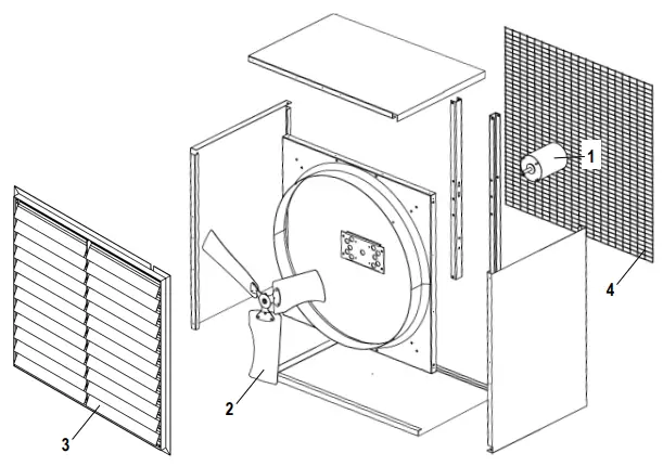
Performance
| Model | HP | F.L.A. | Volt. | Ph | Hz | Motor RPM | CFM | Dbs @ 7ft 0.0SP | |||
| 0.0″ SP | 0.1″ SP | 0.2″ SP | 0.3″ SP | ||||||||
| 36D370S | 1/2 | 5.2/2.8-2.6 | 115/208-230 | 1 | 60 | 825 | 10,300 | 8,700 | 7,180 | – | 76 |
| 36D370TS | 1/2 | 2.3-2.2/1.1 | 208-230/460 | 3 | 60 | 825 | 10,315 | 8,730 | 7,185 | – | 76 |
| 36DL750S | 1 | 11.0/5.8-5.5 | 115/208-230 | 1 | 60 | 825 | 12,510 | 10,635 | 8,830 | 6,045 | 78 |
| 36DL750TS | 1 | 4.8-4.6/2.3 | 208-230/460 | 3 | 60 | 825 | 12,505 | 10,625 | 8,825 | 6,035 | 78 |
| 36XL550S | 3/4 | 6.4/3.4-3.2 | 115/208-230 | 1 | 60 | 1725 | 11,010 | 9,580 | 8,210 | 5,470 | 73 |
| 36XL750S | 1 | 9.4/5.0-4.7 | 115/208-230 | 1 | 60 | 1725 | 12,005 | 10,450 | 9,015 | 6,675 | 77 |
| 36XL750TS | 1 | 3.8-3.6/1.8 | 208-230/460 | 3 | 60 | 1725 | 12,010 | 10,460 | 9,025 | 6,690 | 77 |
| 42DL750S | 1 | 11.0/5.8-5.5 | 115/208-230 | 1 | 60 | 825 | 15,570 | 12,540 | 11,140 | 6,905 | 80 |
| 42DL750TS | 1 | 4.8-4.6/2.3 | 208-230/460 | 3 | 60 | 825 | 15,565 | 12,530 | 11,135 | 6,900 | 80 |
| 42XL750S | 1 | 9.4/5.0-4.7 | 115/208-230 | 1 | 60 | 1725 | 15,450 | 12,490 | 11,135 | 7,080 | 79 |
| 42XL750TS | 1 | 3.8-3.6/1.8 | 208-230/460 | 3 | 60 | 1725 | 15,455 | 12,495 | 11,135 | 7,085 | 79 |
| 42XL1125S | 1 1/2 | 13.2-13.0 | 208-230 | 1 | 60 | 1725 | 18,150 | 15,695 | 12,780 | 10,420 | 81 |
| 42XL1125TS | 1 1/2 | 5.0-4.8/2.4 | 208-230/460 | 3 | 60 | 1725 | 18,145 | 15,690 | 12,770 | 10,415 | 81 |
| 48XL750S | 1 | 9.4/5.0-4.7 | 115/208-230 | 1 | 60 | 1725 | 19,020 | 17,015 | 14,670 | 11,070 | 80 |
| 48XL750TS | 1 | 3.8-3.6/1.8 | 208-230/460 | 3 | 60 | 1725 | 19,035 | 17,030 | 14,685 | 11,080 | 80 |
| 48XL1125S | 1 1/2 | 13.2-13.0 | 208-230 | 1 | 60 | 1725 | 23,740 | 21,545 | 18,435 | 13,930 | 82 |
| 48XL1125TS | 1 1/2 | 5.0-4.8/2.4 | 208-230/460 | 3 | 60 | 1725 | 23,735 | 21,555 | 18,450 | 13,985 | 82 |
Troubleshooting Guide
| Symptom | Possible Cause(s) | Corrective Action |
| Fan will not start | 1. Tripped circuit breaker | 1. Reset circuit breaker |
| 2. Defective motor | 2. Repair or replace | |
| 3. Incorrectly wired | 3. Shut off power, check for proper connections | |
| 4. Electricity turned off | 4. Contact local power company | |
| Excessive noise or vibration | 1. Blade is hitting housing | 1. Free blade of obstruction |
| 2. Blade is bent | 2. Replace blade | |
| 3. Fan not securely anchored | 3. Secure properly | |
| 4. Bad/noisy motor bearings | 4. Replace motor | |
| Insufficient airflow | 1. Incorrect voltage applied | 1. Wire properly |
| 2. Defective motor | 2. Replace motor | |
| 3. Propeller is damaged | 3. Replace propeller | |
| 4. Airflow is blocked | 4. Remove obstructions | |
| 5. Not enough intake air | 5. Add additional air intake openings | |
| 6. Fan is dirty | 6. Clean fan guards/screens, motor and propeller | |
| Motor overheats or trips out | 1. Over/under line voltage | 1. Contact local power company |
| 2. Defective motor | 2. Replace motor | |
| 3. Fan is dirty. | 3. Clean fan guards/screens, motor and propeller | |
| 4. Not enough intake air | 4. Add additional air intake openings |
Maintenance
- Periodic maintenance schedules should be set to assure reliability and performance of the fan. This maintenance should include inspection of all fasteners & drive components, checking propeller torque and proper cleaning of the complete fan assembly.
- Check for excessive vibration while fan is running.
- Periodically inspect and tighten all set screws and hardware.
- Ensure all mounting hardware, chains, etc. are properly secured.
- Motors feature permanently sealed ball bearings and require no further lubrication.
- The fan propeller should be periodically cleaned to assure proper balance and performance.
MH-0004 Rev. 053122 www.air-movement.com


