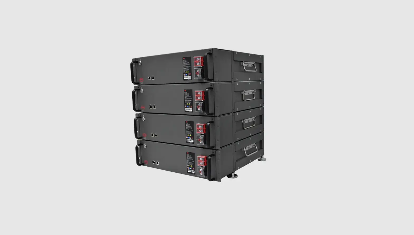
BYD LV FLEX Battery Box Instruction Manual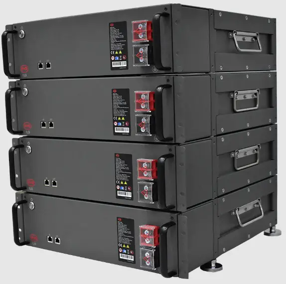
VALIDITY
This document is valid for the BYD Battery-Box Premium LV BMU -IP55 (Batttery Management Unit) (“BMU”) from firmware version 1.22.
INTENDED USE
BMU is applicable for the BYD Battery-Box Premium LV system(s)(LV FLEX, LV FLEX LITE, LVS,
LVS LITE, LVL) (“Battery-Box”), and works as a control unit for the system(s).
Product Description
BMU is equipped with WLAN. The APP Be Connect 2.0 could communicate with BMU through the WLAN.

https://apps.apple.com/us/app/book-my-university-bmu/id1465384128

The WLAN name and password are on the label of BMU.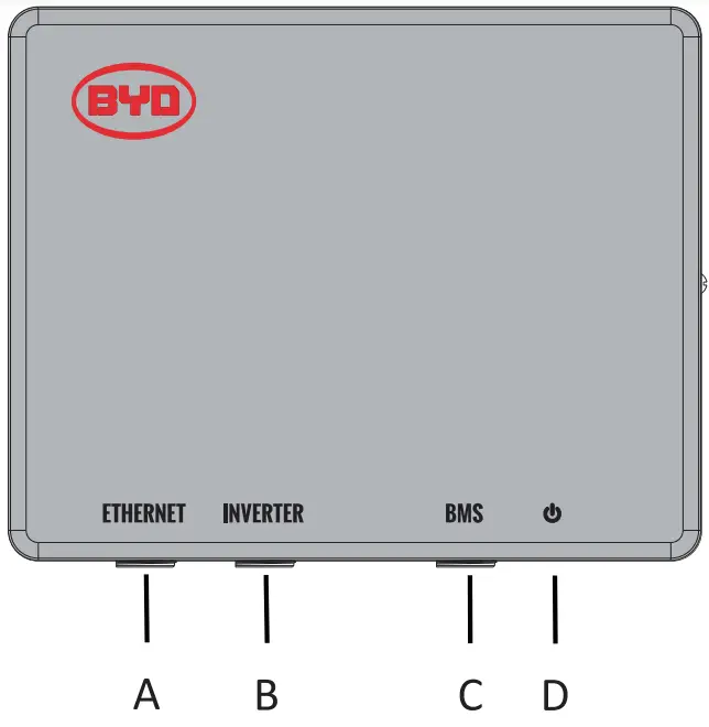
A: Ethernet port
B: RJ45 port for connection with an inverter
C: RJ45 port for connection with Battery-Box
D: LED Button
Assignment of Port B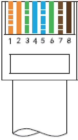
| No | Assignment |
| 1 | Unused |
| 2 | Unused |
| 3 | Unused |
| 4 | CAN H |
| 5 | CAN L |
| 6 | Unused |
| 7 | Unused |
| 8 | Unused |
SCOPE OF DELIVER
- 1X BMU
- 1X Instruction Manual
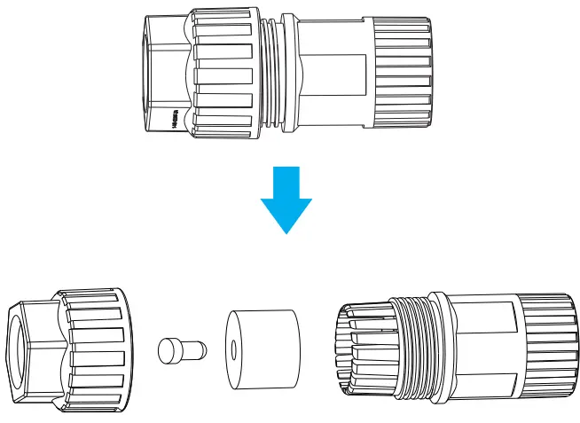
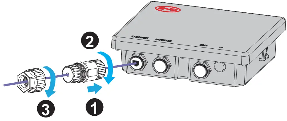
- 3X Connectors
- 1X Hanger
TECHNICAL DATA
| Communication | Ethernet/CAN |
| Input voltage* | 40-60 V |
| Input current | 200 mA |
| Weight | 1.3 kg |
| Dimensions (LV WX H) | 220 mm X 60 mm X 176 mm |
| Ambient temperature in operation | -10°C to 50°C |
| Relative humidity (non-condensing) | 5% to 95% |
| Degree of protection (in accordance with IEC 60529) | IP55 |
*BMU is powered by Battery-Box through the network cable. No other power supply is needed.
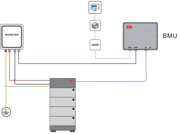
CONNECTION DIAGRAM
| EMU | SILL | STUDER | VICTRON | SELECTRONIC | SOLAREOGE | 0000WE | MACRON | E4NNODER | SOLIS | Oes. | |
| CAN H | 4 | 4 | 4 | 7 | 1 | 4 | 4 | 4 | 14 | 4 | 4 |
| CAN 0 | 5 | 5 | 5 | 8 | 2 | 5 | 5 | 5 | 12 | 5 | 5 |
- Detailed connection instructions with inverters could be read in the Battery-Box Quick Start Guide.
- The communication cable between BMU and an inverter cannot be longer than 20 meters. And the cable should be CAT 5 shield or above
- Please make sure the correct pins are connected between BMU and an inverter.
- The connection between BMU and Battery-Box should be the Straight-Through Wired Cable.
- Connected to the Internet is highly recommended.
- The WLAN of BMU will switch off in 5 hours from turning on.
Press the LED Button once when BMU is on could activate the WLAN again
Press the LED Button three times in six seconds, each time around 1 second could reset the WLAN
Press the LED Button three times in six seconds, each time around 1 second could reset the WLA
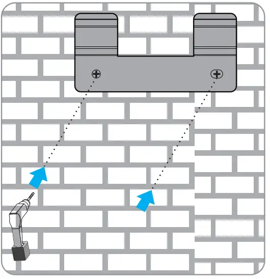
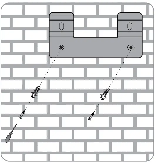
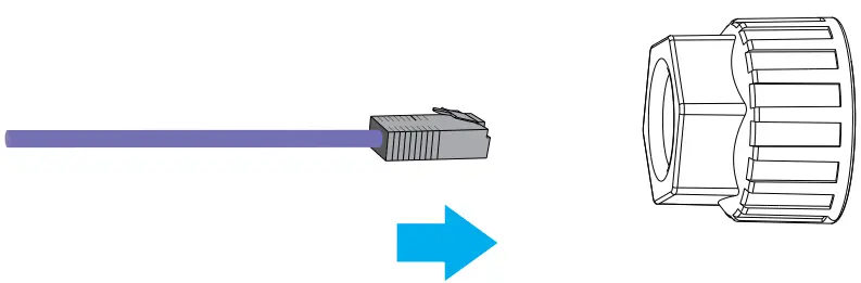
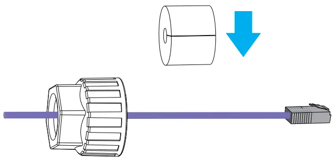
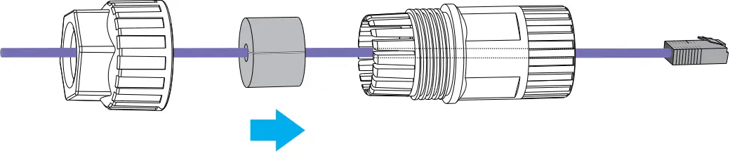
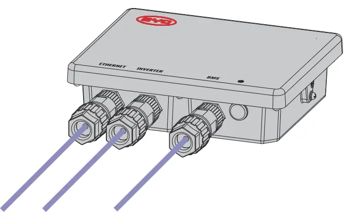
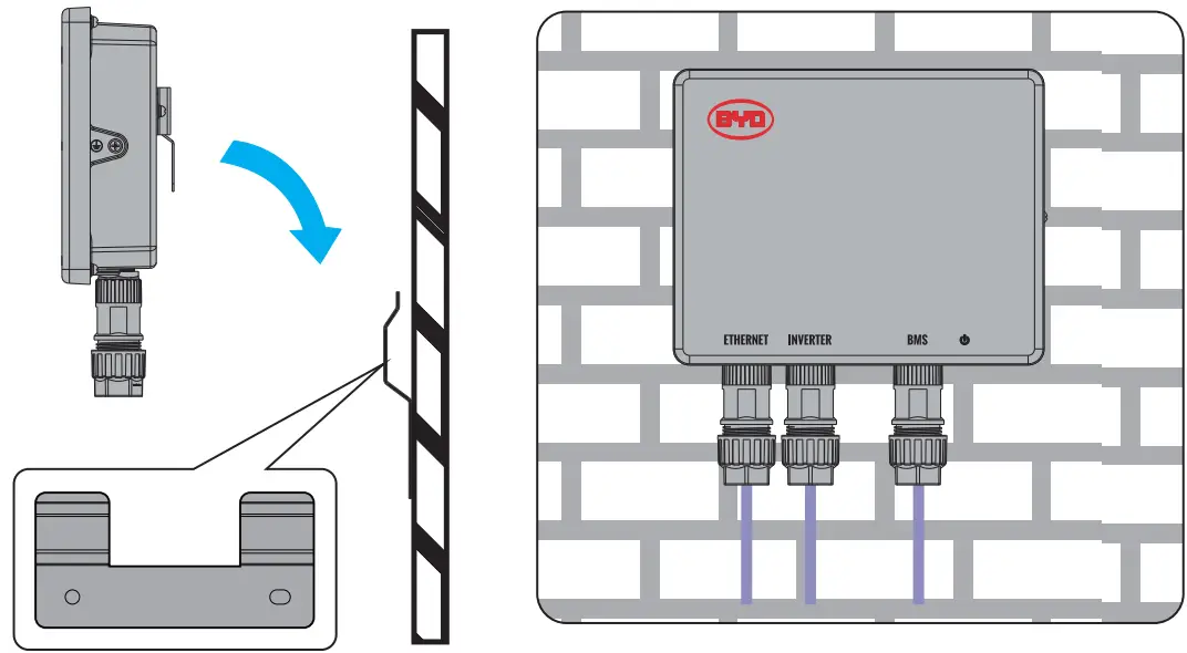
MOUNTING AND CONNECTION
Install BMU on the wall or a rack. The recommended expansion screw size is M6X 12. The minimum distance from the ground is 180mm.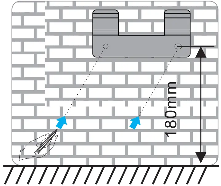
COMMISSIONING
- Make sure an inverter, Battery-Box, and BMU are correctly connected.
- Press the LED Button on Battery-Box for 3 seconds.
- Refer to Battery-Box Operating Manual for further steps.
UPDATING FIRMWARE
The firmware of BMU could only be updated when it operates with Battery-Box. Please refer to Battery-Box Operating Manual for further information.
LED STATUS
Flashing white and blue Alternatively 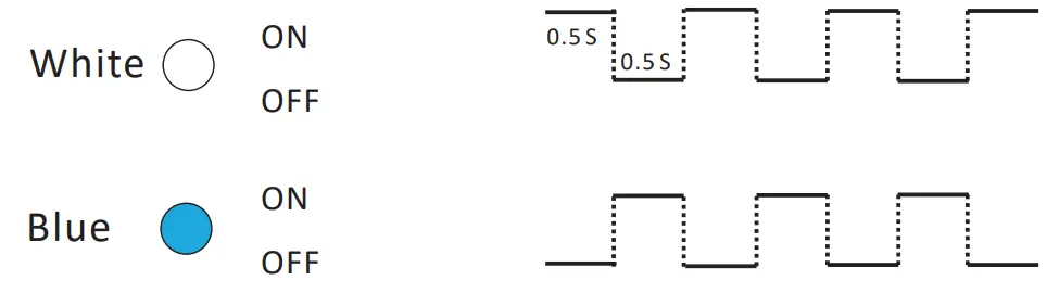 = The battery system is initiating.
Static White= ![]() Idle ( the battery system is neither charging nor discharging)
Idle ( the battery system is neither charging nor discharging) 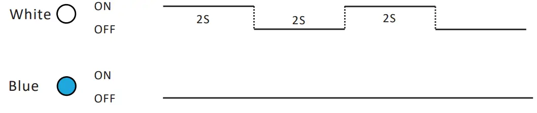 .= The battery system is charging.
Flashing White Slowly 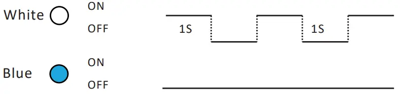 = The battery system is discharging.
Flashing white quickly= The battery system is discharging, and the SOC of Battery-Box is below 15%.
Flashing white and glowing blue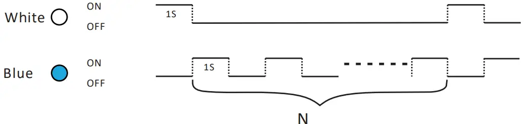 = An error has occurred**
When an error happens, refer to the Operating Manual of the corresponding Battery-Box for more details.
DISPOSAL
Following the applicable regulations for electronic waste to dispose of BMU.


