BYD Battery-Box LV Flex Lite User Guide
Make sure to always use the latest version of this service document, available at: www.bydbatterybox.com
Important: The installation and all other kinds of works or measurements in combination with the Battery-Box Premium are only allowed by professional and qualified electricians.
This checklist is a shortened assistance for the Battery-Box and does notre place the original manual, which can be found on www.bydbatterybox.com / www.eft-systems.de / www.alpspower.com.au. Subject to technical modifications; no responsibility is accepted for the accuracy of this information. Attention: Improper handling can cause danger and damage.
GENERAL STEPS
Make sure to always use the latest version of this service document, available at: www.bydbatterybox.com
Please proceed first with the installation steps by:
No. | Name | Description |
| 1.1 | Configuration | Check if the configuration is correct. Refer to latest “BYD BATTERY-BOX LV Flex Lite MINIMUM CONFIGURATION LIST ”(V1.0 or above) available at: www.bydbatterybox.com Make sure the inverter is configured correctly |
| 1.2 | Correct external cabling |
Notes about DC connection:
|
| 1.3 | Latest Firmware | Always install / update the newest Firmware! Note: If not stated otherwise, Wi-Fi password is BYDB-Box |
| 1.4 | App Configuration | To complete the commissioning, the configuration of the battery via mobile device app “Be Connect 2.0” (BC APP) or PC app “Be Connect Plus” (BCP) is mandatory! |
| 1.5 | Restart | After app configuration, please perform a proper restart of the system by switching off the battery correctly (press LED Button on BMU for 5 sec). Make sure all LEDs of the battery are completely off. 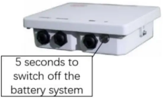 Figure 1 power off BMU Then follow the correct switch on procedure (see step 1.6) |
| 1.6 | Switch On procedure | Correct switch on procedure is important for a correct operation
|
| 1.7 | Checking the correct operation | The system runs properly if: -Inverter displays battery SOC correctly -System charges / discharges Note: If you cannot complete the commissioning, then turn off the battery before you leave the site and make sure all LEDs are off to avoid a discharge of the battery. |
ERROR ANALYSIS
Please refer to the general steps before proceeding, see chapter 1.
BMU shows no reaction/ No LED
LED of BMU does not light up, although the battery is ON.
No. | Name | Description |
| 2.1.1 | Check correct cable port | Make sure that the correct data cable port has been used at the BMU (“BMS” port. Do not mix with “inverter” or “Ethernet” port). |
| 2.1.2 | Replace Comm Cable | Try a completely new communication cable between battery and BMU. Note: Sometimes it might be necessary to unplug the communication cable and plug it again while batteries are switched on. |
| 2.1.3 | Voltage measurement | Battery voltage should be around 50V, see Section 3.1 for voltage measurement. If yes: try another BMU (if available). If no: check another cable or Try another LV FLEX Lite if multiple batteries are installed in the system. |
| 2.1.4 | Only LED faulty? | In some rare cases, the LED of the BMU is faulty. To check that: check if there is a Wi-Fi access point of the Battery-Box. If so, only the external LED is inactive and a commissioning could still work. |
| 2.1.5 | Module Exclusion Method | Check if system works when bypassing the suspected module. |
| 2.1.6 | BMU exchange | If problem remains, try another BMU, if available. |
Some modules do not show any reaction / No LED on module
LEDs of some modules do not light up, although button on topmost module is pressed for 3 seconds.
No. | Name | Description |
| 2.2.1 | Comm cable | Try to unplug the comm cable between the first affected LV Flex Lite module and the one above it, and plug it again. Or try a completely new comm cable between the first affected LV Flex Lite module and the one above it |
| 2.2.2 | Only LED faulty? | In some rare cases, the LED of the module is faulty. To check that: use BC APP or BCP to check whether the BMS information of this module could be detected. |
| 2.2.3 | Switch on the suspected module | Press the LED button for three seconds to power one the suspected module. If the LED cannot be lighted up, the battery module is faulty. |
| 2.2.4 | Voltage measurement | Check voltage of the affected module(s). See Section 3.1. Voltage should be around 50V. If voltage is lower than 38V, it might be unable to power on. Try to charge it as soon as possible if a charger is available, or replace it. |
| 2.2.5 | Module Exclusion Method | Module Exclusion Method (see section 3.2): Check if the system works when bypassing the suspected module. Remove it if bypassing works. |
Problem with the Firmware Update / App Configuration
The Battery Management consists of two components: the BMU and the BMS. The Firmware Update from BC APP and BCP will update the BMU, which will then update the BMS. The BMS update can take up to 30 minutes until the firmware is updated on the BMS.
No. | Name | Description |
| 2.3.1 | Correct app and Firmware | Make sure to have the latest BC APP (>2.1.0) and Battery Firmware (download inside BC APP) on your mobile device before connecting BC APP with the battery Wi-Fi. If BC APP cannot be installed, or other general problems occur with BC APP:
|
| 2.3.2 | Wi-Fi cannot be found / Wi-Fi unstable | For BMU version V1.21 (or above), the Battery Wi-Fi turns off 5 hours after the start of the Battery. To reactivate the Wi-Fi, press the LED button about 1 second or restart the system. To reset the Wi-Fi module, press the LED button three times (each time around one second) within 6 seconds. If problem remains:
|
| 2.3.3 | App reports: “The battery system may be busy, please try again later” | Battery-Box is busy (e.g. the battery could be updating the firmware). Please wait 10 minutes and try again. |
| 2.3.4 | Proper restart | Note: Whenever the configuration via BC APP / BCP is changed, a restart of the battery is necessary to make sure that all changes come into effect.
|
| 2.3.5 | Close and restart BC APP | If BC APP does not react anymore after some minutes loading during the update process, close (close the program completely) and restart BC APP. Or try with BCP (section 2.9) |
| 2.3.6 | BMS Version not updated | BC APP will only update the BMU. The BMU will update the BMS, which can take up to 30 minutes. If the BMS Version is not updated after 30min with stable inverter communication, follow the below Process:
|
Incorrect output voltage / No BMS Data
No. | Name | Description |
| 2.4.1 | App Configuration and Firmware | Please check if BC APP configuration was successful and the Firmware is the most recent one. If there are problems, please refer to Section 2.3 Note: It is important to select the correct module quantity. The quantity you need to select refers to the overall quantity of LV Flex Lite modules and not to the quantity of towers. For example, if you have 2 towers connected in parallel, and 4 modules in each tower, you need to select the module quantity of “8” in the BC APP /BCP. Note: Don`t forget to properly restart system after changing configuration! |
| 2.4.2 | Proper restart | Note: Whenever the configuration via BC APP / BCP is changed, a restart of the battery is necessary to make sure that all changes come into effect.
|
| 2.4.3 | BMU<>BMS Communication | Make sure that the comm cable is connected to the right port of BMU (the one labeled as “BMS”). Replace comm cable between BMU and battery. |
| 2.4.4 | Comm cable between modules | Try to unplug the comm cable between the first affected LV Flex Lite module and the one above it, and plug it again. Or try a completely new comm cable between the first affected LV Flex Lite module and the one above it |
| 2.4.5 | Check terminal resistor | Make sure that the terminal resistor is connected to the OUT port (Terminal resistor properties: 120Ω resistor between pin 5 and 6) If it was connected already, then please remove it and try without it to rule out a faulty terminal resistor. Don’t forget to properly restart system afterwards. |
| 2.4.6 | Module Exclusion Method | Refer to Section 3.2 to identify a potentially faulty module. |
| 2.4.7 | Further checking | If problem remains:
|
Communication problem with Inverter
No. | Name | Description |
| 2.5.1 | Configuration | Check if the inverter is correctly selected when configuration. Refer to latest “BYD BATTERY-BOX LV FLEX LITE MINIMUM CONFIGURATION LIST” (V1.0 or above) available at: www.bydbatterybox.com Make sure the inverter is configured correctly |
| 2.5.2 | Inverter settings | Make sure to configure the battery correctly on the inverter interface. Refer to inverter manual for details. |
| 2.5.3 | Comm cable | Confirm PIN / Cable Configuration for the specific inverter model (see manual) Replace the communication cable (min. CAT5!) |
| 2.5.4 | Check inverter status | Check whether the inverter has been successfully powered on by the battery. If the inverter has not been powered on, check whether the battery voltage is within the inverter operating range or not. If the battery voltage is lower than that, refer to section 3.3. |
| 2.5.5 | Further checking | If problem remains:
|
SOC & charging logic
No. | Name | Description |
| 2.6.1 | SOC jumps | The SOC of an LFP battery cannot be measured. It is a calculated value. In general, the state of charge (SOC) of a battery is calculated using the voltage, but other factors such as temperature, current flow and charging behavior also play a role. The calculation of the state of charge is generally more precise if the battery regularly sees full cycles. Every now and then an SOC correction / calibration might occur. That is normal. |
| 2.6.2 | Charging & discharging logic | Charging & discharging is generally controlled by the inverter. |
| 2.6.3 | Battery Logs / History Data | Download and provide all the historic battery log files with BCP in order to identify the root cause. See section 2.9 for details. You can also upload logs with BC APP. See section 2.10. |
Unexpected shutdown
System has been successfully commissioned in the past and did run for some time. Later on an unexpected shutdown occurred.
No. | Name | Description |
| 2.7.1 | Inverter Communication | The battery only works with a compatible external inverter. If for whatever reason the communication between battery and inverter is lost, the battery will shut down itself within 30 minutes. Therefore, check which one did shut down first (battery or inverter) and check if inverter is properly detecting battery (e.g. showing correct SOC or temperature). If problem remains, check according to section 2.5. |
| 2.7.2 | Battery Logs / | Sporadic alarms are hard to detect as they only occur sometimes. Therefore, it is very important to download and provide all the |
| History Data | historic battery log files in order to identify the root cause. See section 2.9 for details. You can also upload logs with BC APP. See section 2.10. | |
| 2.7.3 | Inverter Warning & Monitoring | Unexpected Shutdown can be caused by overall system settings. Therefore, it is necessary to evaluate inverter data as well.
|
BMU/BMS LED Event Code (EC)
A constant white LED refers to standby mode. White blinking means charge or discharge. When the battery is initiating, the LED will flash white and blue with an interval time of 0.5 seconds (normal during startup). When the LED flashes blue with an interval time of 1 second it indicates an event code. We start to count when the white LED begins to flash, then we count how many times white and blue LED flashes. (Also refer to the manual!)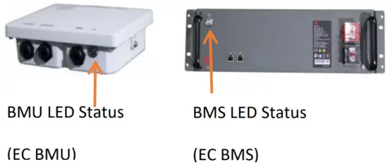
Figure 2 BMU and BMS LED Status
Example:
- 1 x white, 6 x blue → EC 106
- 1 x white, 11 x blue → EC 111
- 3 x white, 3 x blue → EC 303
Note: every LV Flex Lite Module has its own BMS. The Event Code of the BMS willtherefore be shown in the LED of the module.
Most Errors come from a faulty communication line, incorrect app configuration or missing restart after app-configuration. Please go in detail through: Section 1, 2.2 & 2.3
Note: if the system is not correctly configured with app, the event code (EC) might be misleading.
EC BMU | EC BMS | Measure |
| No LED | / | See section 2.1. |
| / | No LED | See section 2.2 |
| Abnormal LED flickering | / | See section 2.1 Module Exclusion Method (see section 3.2): Check if the system works when bypassing the suspected module |
| EC 101 | / | Initialization Failure.
If the problem remains:
|
| EC 102
EC 105 | / | Incorrect module quantity / Module not detected. See section 2.4
If problem remains:
|
| EC 103 | EC 108 | PreCharge Fault.
If problem remains:
|
| EC 104 | EC 101 | Short circuit / DC reverse connection.
If problem remains:
|
| EC 104 | EC 102 up to EC113 (All other than 101) | One of the BMS (modules) reports an event message.
|
| EC 106 | / | No communication with Inverter.
|
| EC107 | / | Model type error. Please check the configuration, make sure to choose the right model type. |
Be Connect Plus (BCP)
Be Connect Plus is a Windows-PC tool. With BCP you can:
- read the battery information,
- configure the battery system
- update BMU & BMS firmware
- Export / download battery logs (From BMU and all BMS)
BCP is constantly being improved and updated. Make sure to use the latest program version. You can download the latest version of the Tool on www.bydbatterybox.com / www.eft-systems.de /
www.alpspower.com.au.
For the service analysis, please download and provide the data / logs as described in the program instructions (see PDF manual inside of program ZIP archive).
Note: You need a computer with Windows that will be connected to the battery Wi-Fi. Login as Installer to Be Connect Plus, the password is the same as for Wi-Fi: BYDB-Box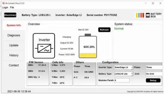
Upload log data with BC APP
When you reach the Status interface, press the three dots on the top left corner, and you will see the menu. Choose Upload Logs, and following the instructions, then you can upload the logs to the BYD server.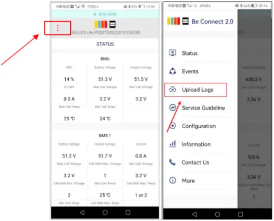
Figure 4 BC APP screenshot
MEASUREMENT
Voltage measurement on pin 7&8
Measure the voltage of pin 7 & 8 while the other side of the cable is connected to the IN port of the Battery and while the Battery is powered on. Voltage should be around 50V.
Note: Pin 7 and pin 8 are very close. It may cause short circuit if they are measured directly! It is better to take a tool as shown in Figure 5.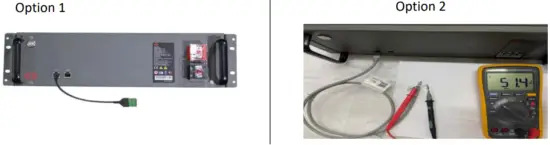
Figure 5 voltage measurement on pin 7&8
Identifying a faulty module / Module Exclusion Method
- Normally a faulty module can be identified with the BCP, BC app or by the LED Code in the battery module. In this case, bypass the module with the Event Code, and commission the remaining system (if it still complies with the minimum configuration list) and check if it runs properly.
If the problem remains, please also bypass the module above the one with the Event Code. - Otherwise, try the LV Flex Lite Modules one by one to identify a possibly faulty module.
If no LED on a module or more modules, check the one above the affected module first, and then the affected one. For example, in a LV Flex Lite system with 4 modules, If top modules have active LED but bottom modules don`t, it indicates a connection issue between modules. If module 1&2 have LED, module 3&4 don`t have LED. Issue is in the connection between module 2 &3.Problem likely to be module 2 (less likely: module 3). - Bypass the affected module and check whether problem disappears. If not, check the module below. To bypass module 2, just connect module 1 directly with module 3 as shown Figure 6.

Figure 6 bypass module 2
Note: The affected module often works without restrictions at the lowest module position of the tower.
Important: The module quantity must be adjusted in BC APP whenever the number of modules has been changed! Don`t forget to perform a proper restart after a new configuration!
Undervoltage
If the minimum cell voltage is less than 1.5 V, it is in undervoltage (check with BC APP or BCP).
- LV Flex Lite Modules with >45 V should be fine and you can go on to check other points according to this service guideline.
- If the module voltage is <40V but the single cell voltage is >1.5V, the battery needs to be charged as soon as possible while avoiding any further discharge. Therefore, shut down the system and search for the problem according to the guideline, while the battery is completely switched off. Also check on the inverter side why the force charge doesn`t work. Do not turn on the battery before making sure the inverter is able to charge the battery.
- If only one module is in undervoltage: remove that module and try commissioning without it (if the remaining modules still comply with the Compatible Inverter List). Otherwise, make sure to avoid further over discharge. (Turn off the system completely)
- If one, or all modules are in undervoltage: Contact BYD local service and make sure to avoid any further discharge of the battery (Turn off the system completely) When contacting the service, make sure to fill the service checklist completely and add the following information:
- Serial Numbers (of the BMU and all affected modules)
- Individual module voltages of all modules (related to Serial number)
- If possible: Upload logs with BC APP (section 2.10) or BCP (section 2.9) and screenshots showing the cell voltages – Initial Firmware (FW) Version of the Battery when the UV happened (BMU and BMS)
- Detailed description how and why the system reached Undervoltage if known. Information when the system was installed and commissioned and in which circumstance and when the undervoltage happened. If the battery was never running before: Why did it never work before, and what was the battery status when the battery was left (on / off / LED).
- Inverter Model, Serial Number and Inverter Logs.
SERVICE TASKS
Please go through the general steps beforehand.
BMU Replacement
Have you detected a faulty BMU?
After replacing the BMU, please do not forget to re-do the configuration and firmware-update with BC APP or BCP.
LV Flex Lite Module Replacement
After replacing a Module, please do not forget to re-do the configuration and firmware-update in BC APP. (Every module has its own BMS)
BYD Battery-Box LV Flex Lite Service Checklist – V1.0
Important: The installation and all other kinds of works or measurements in combination with the BYD Battery-Box are only allowed by professional and qualified electricians. Improper handling can cause danger and damage. This document does not replace the official BYD manuals and documents. No responsibility is accepted for the accuracy of the information.
GENERAL STEPS
Please carefully check all 7 „General Steps“ from page 3 and 4 of the Service Guideline and confirm this in the boxes below:
![]() 1.1 Configuration
1.1 Configuration ![]() 1.4 App Configuration
1.4 App Configuration ![]() 1.7 Correct Operation
1.7 Correct Operation![]() 1.2 Correct external cabling
1.2 Correct external cabling ![]() 1.5 Restart
1.5 Restart![]() 1.3 Latest Firmware
1.3 Latest Firmware ![]() 1.6 Switch on procedure
1.6 Switch on procedure
ERROR RELATED ANALYSIS
Please mark the error related Analysis from Chapter 2 and 3 of the Service Guideline that you checked, and collect all the information related to those Sections.
![]() 2.1 BMU shows no reaction / No LED
2.1 BMU shows no reaction / No LED![]() 2.2 Some modules do not show any reaction / No LED on module
2.2 Some modules do not show any reaction / No LED on module![]() 2.3 Problem with the Firmware Update / App Configuration
2.3 Problem with the Firmware Update / App Configuration![]() 2.4 Incorrect output voltage / No BMS Data
2.4 Incorrect output voltage / No BMS Data![]() 2.5 Communication problem with Inverter
2.5 Communication problem with Inverter![]() 2.6 SOC& charging logic
2.6 SOC& charging logic![]() 2.7 Unexpected shutdown
2.7 Unexpected shutdown![]() 2.8 BMU/BMS LED Event Code (EC)
2.8 BMU/BMS LED Event Code (EC)![]() 2.9 Be Connect Plus (BCP)
2.9 Be Connect Plus (BCP)![]() 2.10 Upload log data with BC APP
2.10 Upload log data with BC APP![]() 3.1 Voltage measurement on pin7&8
3.1 Voltage measurement on pin7&8![]() 3.2 Identifying a faulty module / Module Exclusion Method
3.2 Identifying a faulty module / Module Exclusion Method![]() 3.3 Undervoltage
3.3 Undervoltage
SERVICE INFORMATION
Please fill all available information in below table. Some information like the Serial Number of the BMU is mandatory to receive service.
Service Ticket Number or System ID: ![]()
Installer / Delivery Address / Contact:
Company: ![]()
Contact Person: ![]()
Street / Nr.: ![]()
ZIP / City: ![]()
Phone: ![]()
Email: ![]()
System Information
Battery Configuration (X LV FLex Lite): ![]()
BMU Serial Number: ![]()
BMU Connected to Internet: Yes ![]() No
No ![]() .
.
Inverter Brand + Model: ![]()
Inverter Serial Number: ![]()
Commissioning Date: ![]()
BMU Firmware: ![]()
BMS Firmware: ![]()
Inverter Firmware: ![]()
Inverter Portal Name: ![]()
(State the system name. Provide access)
Service Information
BMU EventCode (EC): ![]()
Inverter Error Code: ![]()
BMS EventCode(s) and related Module Serial Number(s): ![]()
Was the battery charging / discharging before (was the system working normally before?): Yes ![]() No
No ![]() .
.
Get Data of the Battery-Box with the Be Connect Plus (BCP) Programm (see chapter 2.9): ![]()
Description of the Problem: ![]()
Please provide any additional information that is necessary or could help in the analysis of the service case (e.g. serial number of a wrong module, video of a special behaviour; pictures; app screenshots; module voltages… )
By contacting us you confirm, that a qualified person has done the necessary control and collected all available information above.
Service Contact:
BYD Company Limited
www.bydbatterybox.com
Global Sales: [email protected]
Global Service: [email protected]
Battery-Box South Africa Service Partner
AFRIPLUS ENERGY GROUP (PTY) LTD
[email protected]
BYD LATAM Service


