![]()
Pioneering for You
Wilo-Atmos PICO
Installation and operating instructions
Atmos PICO Circulator Pump
General information
About these instructions
These installation and operating instructions are an integral part of the product. Read these instructions before commencing work and keep them in an accessible place at all times.
Strict adherence to these instructions is a precondition for the intended use and correct operation of the product. All information and markings on the product must be observed.
The language of the original operating instructions is German. All other languages of these instructions are translations of the original operating instructions.
Safety
This chapter contains basic information which must be adhered to during installation, operation, and maintenance.
Additionally, the instructions and safety instructions in the other chapters must be observed. Failure to follow the installation and operating instructions will result in a risk of
injury to persons and damage to the environment and the product. This will result in the loss of any claims for damages.
Failure to follow the instructions will, for example, result in the following risks:
- Danger to persons due to electrical, mechanical, and bacteriological factors as well as electromagnetic fields
- Environmental risks due to leakage of hazardous substances
- Property damage
- Failure of important functions of the product
Identification of safety instructions
This installation and operating instructions set out safety instructions for preventing personal injury and damage to property that is displayed in different ways:
- Safety instructions relating to personal injury start with a signal word and are preceded by a corresponding symbol.
- Safety instructions relating to property damage start with a signal word and are displayed without a symbol.
Signal words
DANGER!
Failure to observe the safety instructions will result in serious injuries or death!
WARNING!
Failure to follow the instructions can lead to (serious) injuries!
CAUTION!
Failure to follow the instructions can lead to property damage and a possible total loss.
NOTE
Useful information on handling the product.
Symbols
These instructions use the following symbols:
| Danger due to electrical voltage | |
| General danger symbol | |
 | Warning of hot surfaces/media |
 | Warning of magnetic fields |
| Notes |
Personnel qualifications
Personnel must:
- Be instructed in the locally applicable accident prevention regulations.
- Have read and understood the installation and operating instructions.
Personnel must have the following qualifications: - Electrical work must be carried out by an authorized electrician (in accordance with EN 50110-1).
- Installation/dismantling must be carried out by a qualified technician who is trained in the use of the necessary tools and mounting materials.
- The product must be operated by persons who are instructed in the functioning of the complete system.
Definition of “qualified electrician”
A qualified electrician is a person with appropriate technical education, knowledge, and experience who can identify and prevent electrical hazards.
Electrical work
- Electrical work must be performed by a qualified electrician.
- Nationally applicable guidelines, standards, and regulations as well as specifications by local energy supply companies for connection to the local power supply system must be observed.
- Before commencing work, disconnect the product from the mains and secure it against being switched on again.
- The connection must be protected by means of a residual-current device (RCD).
- The product must be earthed.
- Have defective cables replaced immediately by a qualified electrician.
- Never open the control module and never remove control elements.
Obligations of the operator
- Has all work been carried out by qualified personnel only?
- Ensure on-site contact protection from hot components and electrical hazards.
- Have defective gaskets and connecting cables been replaced?
This device can be used by children from 8 years old as well as persons with limited physical, sensory or mental capabilities or lack of experience and knowledge if they are supervised or instructed in the safe use of the device and they understand the dangers that may arise. Children are not allowed to play with the device. Cleaning and user maintenance may not be carried out by children without supervision.
Product description and function
Overview
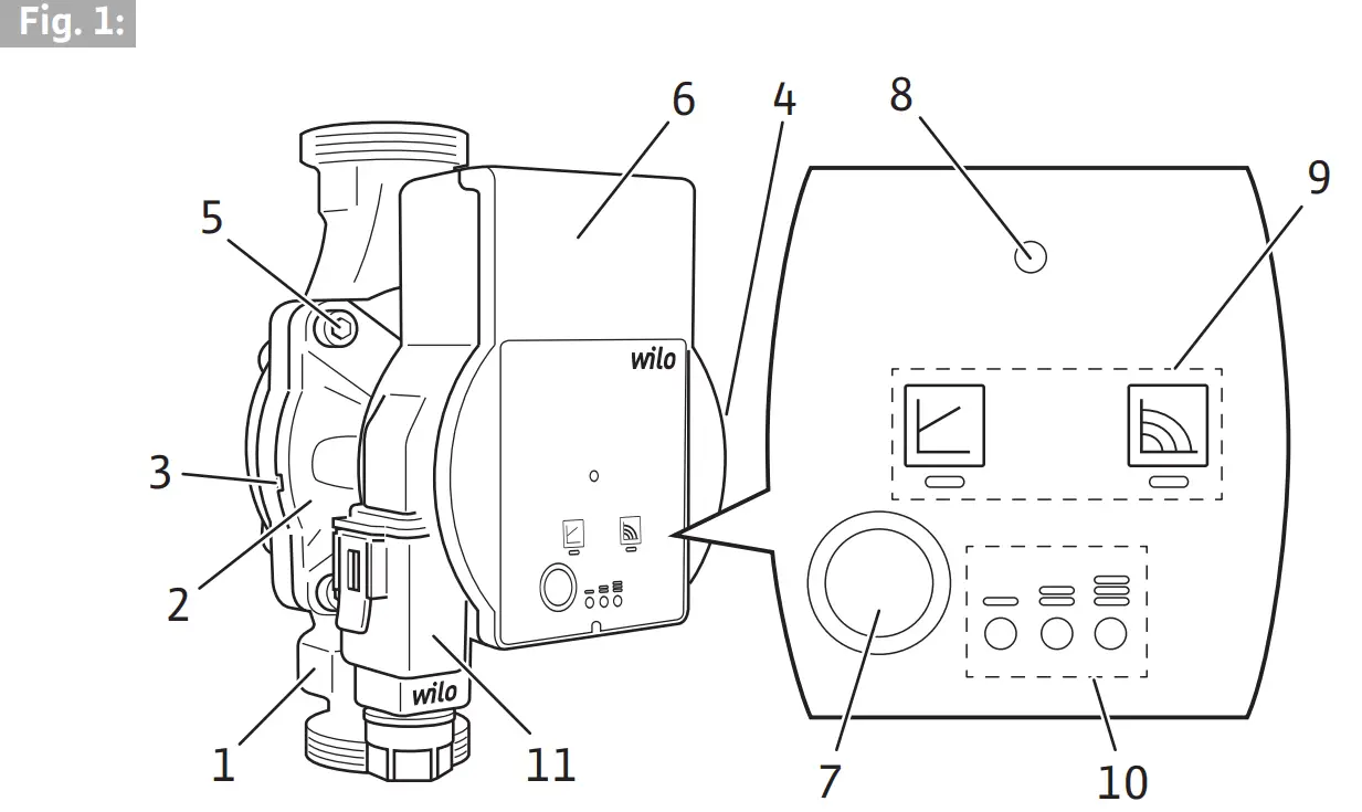
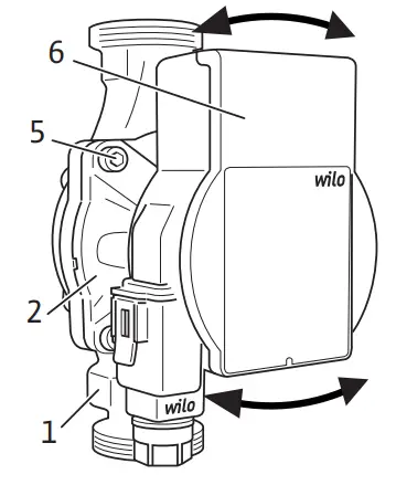
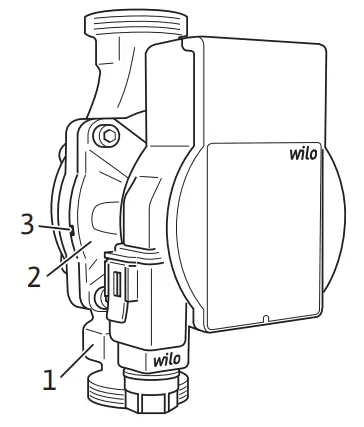
Wilo-Atmos PICO (Fig. 1)
- Pump housing with screwed connections
- Glandless pump motor
- Condensate drain openings
(4x around the circumference) - Rating plate 5Housing screws
- Control module
- Operating push button
- Run signal/fault signal LED
- Display of selected control mode
- Display of selected characteristic curve (I, II, III)
- Wilo-Connector, electrical mains connection
Function
High-efficiency circulator for hot-water heating systems with integrated differential pressure control. The Control mode and delivery head (differential pressure) is adjustable.
The differential pressure is controlled via the pump speed.
Type key
Example: Wilo-Atmos PICO 25/1-6-130
| Atmos PICO | High-efficiency circulator |
| 25 | Screwed connection DN 25 (Rp 1) |
| 1-6 | 1 = Minimum delivery head in m (adjustable down to 0.5 m) 6 = Maximum delivery head in m at Q = 0 m³/h |
| 130 | Port-to-port length: 130 mm or 180 mm |
Technical data
| Connection voltage | 1 ~ 230 V ± 10 %, 50/60 Hz |
| Protection class IP | See rating plate (4) |
| Energy efficiency index EEI | See rating plate (4) |
| Fluid temperatures at max. ambient temperature +40 °C | -10 °C to +95 °C |
| Fluid temperatures at max. ambient temperature +25 °C | -10 °C to +110 °C |
| Permitted ambient temperature | -10 °C to +40 °C |
| Max. operating pressure | 10 bar (1000 kPa) |
| Min. inlet pressure at +95 °C/+110 °C | 0.3 bar/1.0 bar (30 kPa/100 kPa) |
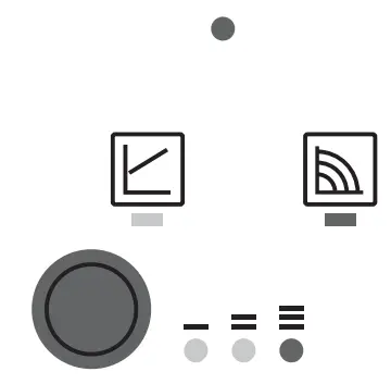
Indicator lights (LEDs)
![]()
- Signal display
- LED is lit up in green in normal operation
- LED lights up/flashes in case of a fault (see chapter 10.1)
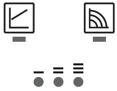
- Display of selected control mode Δp-v and constant speed
- Display of selected pump curve (I, II, III) within the control mode
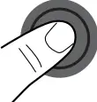
Operating button
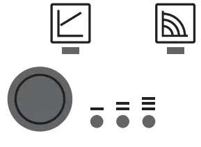
Press
- Select control mode
- Select pump curve (I, II, III) within the control mode
3.1 Control modes and functions
Variable differential pressure Δp-v (I, II, III)
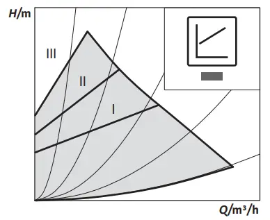
Recommended for two-pipe heating systems with radiators to reduce the flow noise at thermostatic valves.
The pump reduces the delivery head to half in the case of decreasing volume flow in the pipe network.
Electrical energy saving by adjusting the delivery head to the volume flow requirement and lower flow rates.
There are three pre-defined pump curves (I, II, III) to choose from.
![]() NOTE
NOTE
Factory setting: Δp-v, pump curve II
Constant speed (I, II, III)
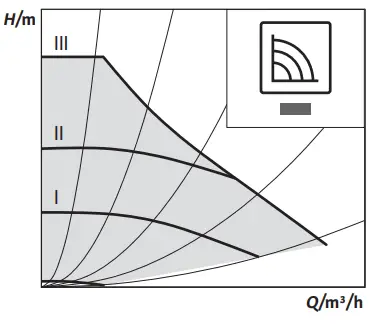
Recommended for systems with fixed system resistance requiring a constant volume flow.
The pump runs in three prescribed fixed-speed stages (I, II, III).
Intended use
The high-efficiency circulators in the Wilo-Atmos PICO series are exclusively designed for circulating fluids in hot-water heating systems and similar systems with constantly changing volume flows.
Permitted fluids:
- Heating water according to VDI 2035 (CH: SWKI BT 102-01).
- Water-glycol mixtures* with a maximum of 50 % glycol.
* Glycol has a higher viscosity than water. If glycol is added, the delivery date of the pump must be corrected to suit the mixing ratio.
NOTE
Only add ready-to-use mixtures to the system.
Do not use the pump to mix the fluid in the system.
Intended use includes observing these instructions and the data and markings on the pump.
Misuse Any use beyond the intended use is considered misuse and will result in the loss of all liability claims.
WARNING!
The danger of injury or material damage due to improper use!
- Never use non-specified fluids.
- Never allow unauthorized persons to perform work.
- Never operate the pump outside of the specified limits of use.
- Never carry out unauthorized conversions.
- Use authorized accessories only.
- Never operate with phase angle control.
Transportation and storage
Scope of delivery
- High-efficiency circulator with 2 gaskets
- Wilo-Connector
- Installation and operating instructions
Transport inspection
Inspect for transportation damage and check completeness immediately after delivery, and claim immediately if necessary.
Transport and storage conditions
Protect from moisture, frost, and mechanical loads.
Permissible temperature range: -10 °C to +50 °C.
Installation and electrical connection
6.1 Installation
May only be installed by qualified technicians.
![]() WARNING!
WARNING!
Risk of burns due to hot surfaces!
Pump housing (1) and glandless pump motor (2) may become hot and result in burns on contact.
- During operation, touch the control module (6) only.
- Allow the pump to cool down before commencing any work.
![]() WARNING!
WARNING!
Risk of burns due to hot fluids!
Hot fluids can result in scalding. Before installing or removing the pump, or undoing the housing screws (5), note the following:
- Allow the heating system to cool down completely.
- Close shut-off devices or drain the heating system.
Preparation
- Choose an installation point that is as easily accessible as possible.
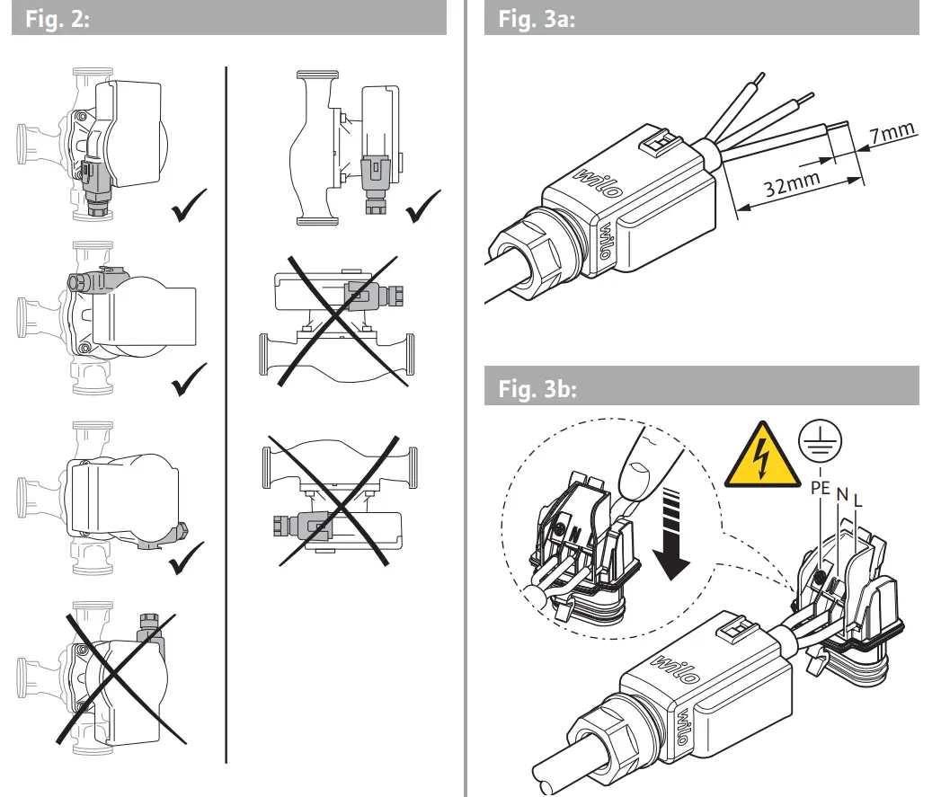
- Observe the pump’s allowable installation position (Fig. 2), and rotate the motor head (2 + 6) if necessary.
CAUTION!
An incorrect installation position may damage the pump.
- Select the installation point in line with the allowable installation position (Fig. 2).
- The motor must always be installed horizontally.
- The electrical connection must never face upwards.
- Install shut-off devices upstream and downstream of the pump to facilitate pump replacement.
CAUTION!
Leaking water may damage the control module.
- Align the upper shut-off device such that leaking water cannot drip onto the control module (6).
- Align the upper shut-off device laterally.
- When installed in the feed of open systems, the safety supply must branch off upstream of the pump (EN 12828).
- Complete all welding and brazing tasks.
- Flush the pipe system.
Rotating the motor head
Rotate the motor head (2 + 6) before installing and connecting the pump.
- If necessary, remove the thermal insulation shell.
![]() WARNING!
WARNING!
Risk of fatal injury from the magnetic field!
Risk of death for people with medical implants due to permanent magnets installed in the pump.
- Never remove the rotor.
- Hold the motor head (2 + 6) and unscrew the 4 housing screws (5).
CAUTION!
Damage to the inner gasket leads to leakages.
- Carefully rotate the motor head (2 + 6).
- Observe the allowable installation position (Fig. 2) and the direction arrow on the pump housing (1).
- Tighten (4-7.5 Nm) the 4 housing screws (5).
- Carefully rotate the motor head (2 + 6) without removing it from the pump housing (1).
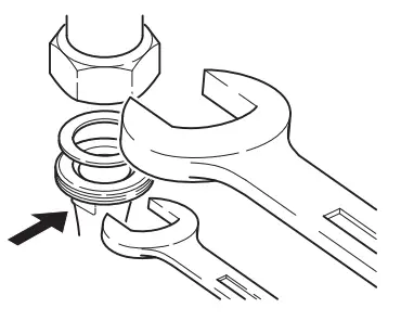
Installing the pump
Observe the following points when installing the pump:
- Note the direction arrow on the pump housing (1).
- Install without tension, with a glandless pump motor horizontal (2).
- Place gaskets in the screwed connections.
- Screw on threaded pipe unions.
- Secure the pump with an open-end wrench against twisting and screwing tightly with the piping
- Re-mount the thermal insulation shell, if applicable.
CAUTION!
Insufficient heat dissipation and condensation water may damage the control module and the glandless pump motor.
- Do not thermally insulate the glandless pump motor (2).
- Ensure all condensate drain openings (3) are kept free.
6.2 Electrical connection
The electrical connection may only be performed by a qualified electrician.
![]() DANGER!
DANGER!
Danger to life due to electrical voltage!
Immediate danger to life if live components are touched.
- Before commencing work, switch off the power supply and secure it against being switched on again.
- Never open the control module (6) and never remove control elements.
CAUTION!
Pulsed mains voltage can lead to damage to electronic
components.
- Never operate the pump with phase angle control.
- When switching the pump on or off using an external control unit, deactivate any voltage pulsing (e.g. phase angle control).
- For applications where it is not clear whether the pump is operated with pulsed voltage, get the control/system manufacturer to confirm that the pump is operated with sinusoidal AC voltage.
- Switching the pump on/off via triacs/solid-state relays must be examined on a case-by-case basis.
Preparation
- The current type and voltage must agree with the specifications on the rating plate (4).
- Maximum backup fuse: 10 A, slow-blow.
- Only operate the pump with sinusoidal AC voltage.
- Note switching frequency:
– On/off switching operations via mains voltage ≤ 100/24 h.
– ≤ 20/h for a switching frequency of 1 min. between switching on/off via mains voltage. - The electrical connection must be made via a fixed connecting cable equipped with a connector device or an all-pole switch with a contact opening width of at least 3 mm (VDE 0700/Part 1).
- Use a connecting cable with a sufficient outer diameter (e.g. H05VV-F3G1.5) to protect against leaking water and to ensure strain relief at the threaded cable connection.
- Use a heat-resistant connecting cable where fluid temperatures exceed 90 °C.
- Ensure that the connecting cable does not make contact with either the pipes or the pump.
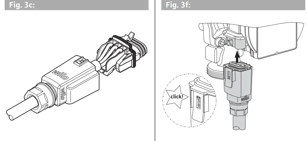
Fitting the Wilo-Connector
- Disconnect the connecting cable from the power supply.
- Observe the terminal allocations (PE, N, L).
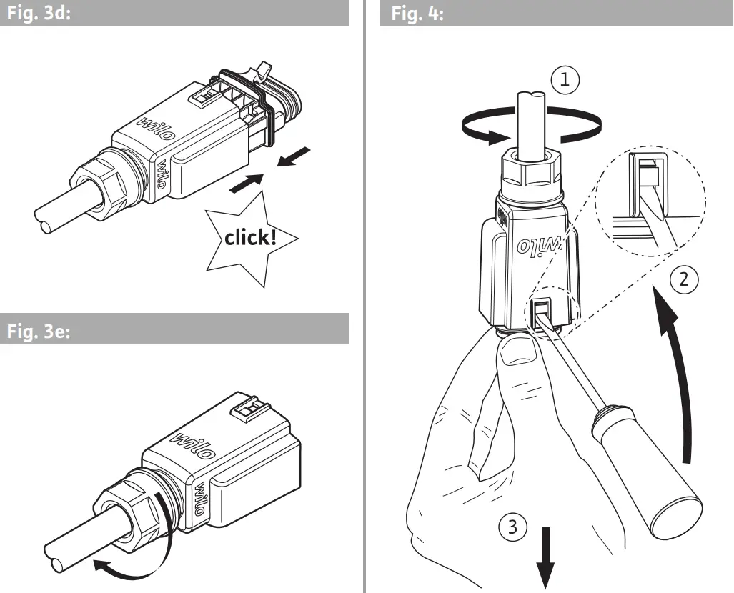
- Connect and fit the Wilo-Connector (Fig. 3a to 3e).
Connecting the pump
- Earth the pump.
- Connect the Wilo-Connector (9) to the control module (6) until it snaps into place (Fig 3f).
Removing the Wilo-Connector
- Disconnect the connecting cable from the power supply.
- Remove the Wilo-Connector using a suitable screwdriver (Fig. 4).
Commissioning
Commissioning only by qualified technicians.
7.1 Venting
- Fill and vent the system correctly.
 The pump vents automatically when first started.
7.2 Setting the control mode
Select control mode
The LED selection of control modes and corresponding pump curves take place in clockwise succession.
- Press the operating button briefly (approx. 1 second). LEDs display the set control mode and pump curve.
The following shows the various possible settings (for example constant speed/characteristic curve III):
 | LED display | Control mode | Pump curve |
| 1 | 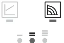 | Constant speed | II |
| 2 |  | Constant speed | I |
| 3 |  | Variable differential pressure Δp-v | III |
| 4 | 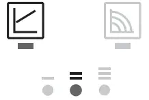 | Variable differential pressure Δp-v | II |
| 5 |  | Variable differential pressure Δp-v | I |
| 6 | 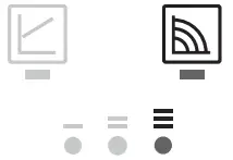 | Constant speed | III |
- Pressing the button for the 6th time returns to the basic setting (constant speed / characteristic curve III).
![]() NOTE
NOTE
All settings and displays are retained if the power supply is interrupted.
Decommissioning
Shutting down the pump
Shut down the pump immediately in case of damage to the connecting cable or other electrical components.
- Disconnect the pump from the power supply.
- Contact Wilo customer service or a specialist technician.
Maintenance
Cleaning
- Carefully remove soiling from the pump on a regular basis using a dry duster.
- Never use liquids or aggressive cleaning agents.
Faults, causes and remedies
The troubleshooting must only be performed by a qualified specialist, and work on the electrical connection must only be performed by a qualified electrician.
| Faults | Causes | Remedies |
| The pump is not running although the power supply is switched on | Electrical fuse defective | Check fuses |
| The pump has no voltage | Resolve the power interruption | |
| Pump making noises | Cavitation due to insufficient suction pressure | Increase the system pressure within the permissible range |
| Check the delivery head and set it to a lower head if necessary | ||
| The building does not get warm | The thermal output of the heating surfaces is too low | Increase setpoint |
10.1 Fault signals
- The fault signal LED indicates a fault.
- The pump switches off (depending on the fault) and attempts a cyclical restart.
| LED | Faults | Causes | Remedy |
| Lights up red | Blocking | Rotor blocked | Activate manual restart or contact customer service |
| Contacting/ winding | Winding defective | ||
| Flashes red | Under/overvoltage | The power supply is too low/high on the mains side | Check mains voltage and operating conditions, and request customer service |
| Excessive module temperature | The module interior is too warm | ||
| Short-circuit | Motor current too high | ||
| Flashes red/green | Generator operation | Water is flowing through the pump hydraulics, but there is no mains voltage at the pump | Check the mains voltage. water quantity/pressure and the ambient conditions |
| Dry run | Air in the pump | ||
| Overload | Sluggish motor, the pump is operated outside of its specifications (e.g. high module temperature). The speed is lower than during normal operation |
If the fault cannot be remedied, contact a specialist technician or Wilo customer service.
Disposal
Information on the collection of used electrical and electronic products
Proper disposal and appropriate recycling of this product prevent damage to the environment and dangers to your personal health.
![]() NOTE
NOTE
Disposal in domestic waste is forbidden!
In the European Union, this symbol can appear on the product, the packaging, or the accompanying documentation. It means that the electrical and electronic products in question must not be disposed of along with the domestic waste.
To ensure proper handling, recycling, and disposal of the used products in question, please note the following points:
- Only hand over these products at designated, certified collecting points.
- Observe the locally applicable regulations! Please consult your local municipality, the nearest waste disposal site, or the dealer who sold the product to you for information on proper disposal. For further information on recycling, go to www.wilo-recycling.com.
DECLARATION OF CONFORMITY
We, the manufacturer, declare under our sole responsibility that these glandless circulating pump types of the series,
Atmos PICO …
The serial number is marked on the product site plate
In their delivered state comply with the following relevant directives:
_ Low voltage 2014/35/EU
_ Electromagnetic compatibility 2014/30/EU
_ Energy-related products 2009/125/EC
and according to regulation 641/2009 on glandless circulators amended by 622/2012
_ Restriction of the use of certain hazardous substances 2011/65/EU + 2015/863
and with the relevant national legislation,
comply also with the following relevant harmonized European standards:
EN 60335-2-51
EN 16297-1
EN IEC 63000
EN 16297-2
EN 61000-6-1:2007
EN 61000-6-2:2005
EN 61000-6-4:2007+A1:2011
EN 61000-6-3:2007+A1:2011

Digital
unterschrieben von
Holger Herchenhein
Datum: 2019.05.27
12:41:58 +02’00’
H. HERCHENHEIN
Senior Vice President – Group Quality
WILO SE
Nortkirchenstrae 100
44263 Dortmund – Germany
| Argentina W11.0 SAUA SON Argentina SA. C1295ABI Ciudad Autancm a de Buenos Aires 1 +54 11 4361 5929 [email protected]Australia WILO Australia Pty Limited Murrarrie. Queensland. 4172 1 +61 7 3907 6900 [email protected] Austria Azerbaijan Benrus Belgium Bulgaria Brazil Canada China Croatia | Cuba WILO SE Oficina Comercial E thick. Sirnona Apto 105 Siboney. La Habana. Cuba 1 +53 5 2 795135 +53 7 272 2330 [email protected]Czech Republic WILO CS. SAO. 25101 Cestice 1 +420 234 098711 [email protected] Denmark Estonia Finland France United Kingdom Greece Hungary India Indonesia | Ireland WL0 keland Limerick 1 +353 61 227566 [email protected]Italy WLO Italia sr.l. Via Novegro.1/A20090 Segrate MI T +39 25538351 [email protected] Kazakhstan Korea Latvia Lithuania Morocco The Netherlands Norway Poland | Portugal Bombas Wib-Salmson Skstem as lidraulcos Lda. 4475-330 Maia 1 +351 22 2080350 [email protected]Romania WLO Romania sr.]. 077040 Corn. Cliajna Jud.11foy 1 +4021 3170164 [email protected] Russia Saudi Arabia Slovakia Slovenia South Africa Spain Sweden Switzerland | Taiwan WLO Taiwan CO. Ltd. 24159 New Taipei City 7+886 2 2999 8676 [email protected] Turkey Ukraine United Arab Emirates USA Vietnam |
WILO SE
Nortkirchenstraße 100
D-44263 Dortmund
Germany
T +49(0)231 4102-0
F +49(0)231 4102-7363
[email protected]
www.wilo.com