LBSA 51.2V 105Ah LiFePO4 Smart Battery User Manual
Safety Precautions
This section describes the safety information that must be observed when working with battery packs. To prevent any damages, or personal injury, and to ensure the performance of the battery packs, please read this section carefully and observe the safety precautions at all times.
Precautions
- It is very important and necessary to read the user manual carefully before installing or using the product. Failure to do so or to follow any of the instructions or warnings in this document can result in electrical shock, serious injury or death, and could damage the battery, or potentially rendering it inoperable.
- If the battery pack is stored for long time, it is required to charge them every six months, and the SOC should be no less than 90%.
- Please recharged the battery pack within 12 hours, after fully discharged.
- All the battery pack terminals must be disconnected before any maintenance.
- Do not use cleaning solvents to clean the battery pack.
- Do not expose the battery pack to flammable or harsh chemicals, or corrosive gases or liquids.
- Do not paint any part of the battery pack, including any internal or external components.
- Do not expose the battery pack to direct sunlight (or extended periods of lime.
- Do not connect the battery pack with PV solar wiring directly.
- Do not insert any foreign object into any part of the battery pack.
Warning
- Do not touch the battery pack with wet hands.
- Do not crush, drop or puncture the battery pack.
- Always dispose of the battery pack according to local safety regulations.
- Store and recharge the battery pack in a manner in accordance with this user manual.
- Ensure reliable grounding.
- Do not reverse the polarity when installing.
- Do not short circuit the terminals, remove all jewellery items that could cause a short circuit before installation and handling.
- Disconnect battery from power or loads, and then power off battery before installation and maintenance.
- The battery packs should be not stacked more than specified numbers.
- Continued operation of a damaged battery pack can result in a fire.
Introduction
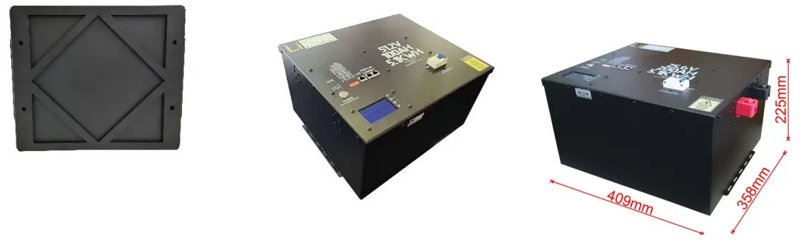
LBSA lithium iron phosphate battery pack is a household renewable energy storage solution developed and produced by Lithium Batteries SA. After fully installation, it is a low-voltage DC battery system with an operating voltage of 51.2V, and works with a low voltage inverter to realize the goal of energy storage for home application.
The battery pack supports parallel connection to expand capacity, which can meet various capacity requirements. It has a built-in battery management system (BMS), which can manage and monitor the pack and cell information including voltage, current and temperature. What’s more, BMS can balance cells charging and discharging to extend cycle life.
Features
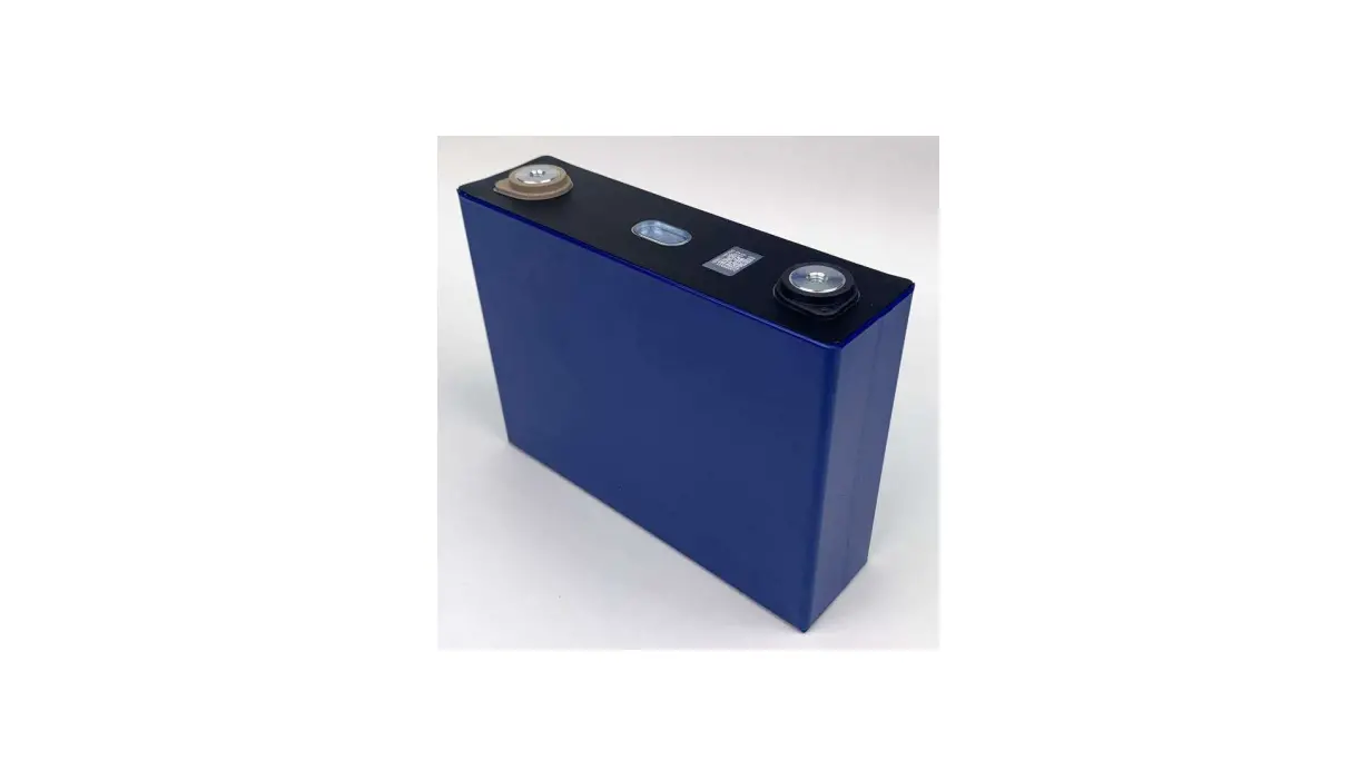
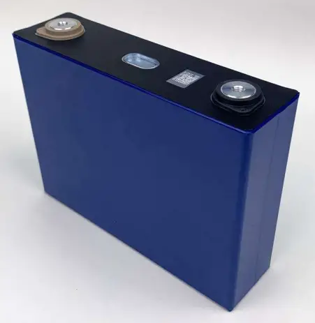
- Battery cell is 3.2V 105Ah aluminium case prismatic cell.
- Battery cell is made from lithium iron phosphate (LiFePO4) with safety performance and longer
cycle life. - BMS has over-discharge, over-charge, over-current, high and low temperature warning and
protection functions. - BMS monitors charge and discharge state, and balances current and voltage of each cell.
- Flexible configuration, max. 16 packs can be connected in parallel for expanding capacity and power with 8 DIP switches.
- Working temperature range is from -20°C-50°C (Charging 0°C-50°C; discharging -20°C-50°C) with excellent discharge performance and cycle life.
Specifications
| Basic Parameters | |
| Nominal Voltage (V) | 51.2V V |
| Nominal Capacity (Ah) | 105Ah(>105Ah) |
| Nominal Power (Wh) | > 5.2KWh @ 0.4c (tested) |
| Dimension (mm) | 409*358*225mm |
| Weight (Kg) | 49KG |
| Discharge Cut-off Voltage (V) | 44V |
| Charge Voltage (Bulk + Absorption) (V) | 56V |
| Max. Charge/Discharge Current (A) | 100A |
| Recommended Charge Current | 50A |
| Communication Interface | CAN |
| Configuration | 16S |
| Working Temperature | 0-50t(Charge) |
| -20-50t (Discharge) | |
| -20–55°C(Storage) | |
| Cell chemistry | Lithium iron phosphate (LiFePO4) |
| Cycle life | a0% capacity state after 4800 cycles at 0.5C, 25°C, 100% DOD |
| IP level | IP 20 |
Interfaces
RESET
Reset button: to start the battery pack, hold the button for 2s to turn on battery pack.
RS485
RS485 communication interface: R145 port, follow RS485 protocol. For transmitting battery pack information between paralleled packs.
Use a standard RJ45 cable.
| Pin | Definition |
| PIN 1, 8 | RS485-B |
| PIN 2, 7 | RS485-A |
| PIN 3, 6 | Ground |
| PIN 4,5 | NC (Bridge weld) |
CAN
CAN communication interface: follow CAN BUS protocol, for output pack information to inverter.
R.1-45 CAN BUS PINOUT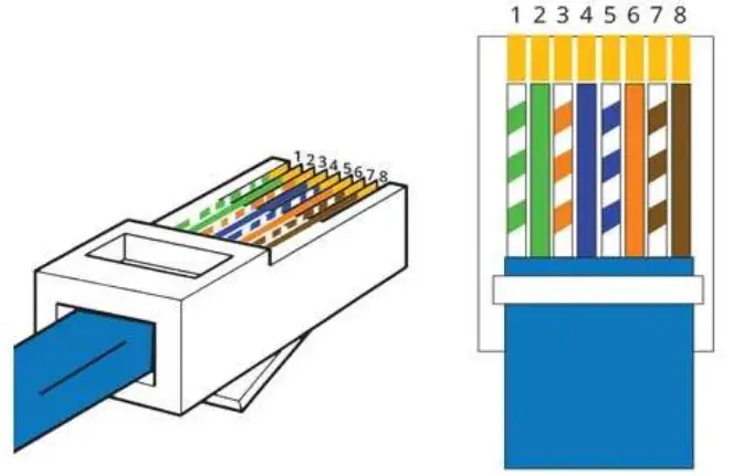
Pin 3: Ground
Pin 4: CAN-H
Pin 5: CAN-L
ADDRESS
ADS Switch: To setup battery address, and to communicate between battery and Inverter.
NOTE: There are 8-bit DIP switches, keep the switch on down side means ‘OFF’, turn up the switch to top side means ‘ON’.
CAN communication DIP address should setup as the following table.
| CAN Communication | |||||||||
| Master Packs (#1, #2, #3, #4 set OFF) tI5, #6, #7, #8 set as follows | Slave Pack (#5, #6, #7, #8 set OFF) #1, #2, #3, #4 set as follows | ||||||||
| 8 | 7 | 6 | 5 | 4 | 3 | 2 | 1 | ||
| One pack | OFF | OFF | OFF | OFF | |||||
| 2 packs in parallel | OFF | OFF | OFF | ON | 1″ slave pack | OFF | OFF | OFF | ON |
| 3 packs in parallel | OFF | OFF | ON | OFF | 2″ slave pack | OFF | OFF | ON | OFF |
| 4 packs in parallel | OFF | OFF | ON | ON | 310slave pack | OFF | OFF | ON | ON |
| 5 packs in parallel | OFF | ON | OFF | OFF | 4″ slave pack | OFF | ON | OFF | OFF |
| 6 packs in parallel | OFF | ON | OFF | ON | 5th slave pack | OFF | ON | OFF | ON |
| 7 packs in parallel | OFF | ON | ON | OFF | 6th slave pack | OFF | ON | ON | OFF |
| 8 packs in parallel | OFF | ON | ON | ON | 7″ slave pack | OFF | ON | ON | ON |
| 9 packs in parallel | ON | OFF | OFF | OFF | 8thslave pack | ON | OFF | OFF | OFF |
| 10 packs in parallel | ON | OFF | OFF | ON | 9″ slave pack | ON | OFF | OFF | ON |
| 11 packs in parallel | ON | OFF | ON | OFF | 10th slave pack | ON | OFF | ON | OFF |
| 12 packs In parallel | ON | OFF | ON | ON | 11th slave pack | ON | OFF | ON | ON |
| 13 packs in parallel | ON | ON | OFF | OFF | 12th slave pack | ON | ON | OFF | OFF |
| 14 packs In parallel | ON | ON | OFF | ON | 13th slave pack | ON | ON | OFF | ON |
| 15 packs in parallel | ON | ON | ON | OFF | 14th slave pack | ON | ON | ON | OFF |
| 16 packs in parallel | ON | ON | ON | ON | 15th slave pack | ON | ON | ON | ON |
ALARM
ALARM light: red LED flash to show the battery alarm status.
And red light permanently to show the battery in protection status of abnormal temperature, over-current, or short-circuit.
RUN
Working light: green LED to show the battery working status.
Details as follows,
| Battery status | Operating Mode | RUN | ALM | LED Light | Remark | |||
| Power off | Standby | OFF | OFF | OFF | OFF | OFF | OFF | OFF |
| Standby | Normal | Solid Green | OFF | According to battery SOC status | Standby mode | |||
| Charge Mode | Normal | Solid Green | OFF | According to battery SOC status | ||||
| Over current warnings | Solid Green | Blink type 2 | ||||||
| Over voltage protection | Blink typel | OFF | OFF | OFF | OFF | OFF | ||
| Temperature, over current protection | Blink typel | OFF | OFF | OFF | OFF | OFF | ||
| Discharge Mode | Normal | Blink type 3 | OFF Blink type 3 | According to battery SOC status | ||||
| Warning | Blink type 3 | |||||||
| Over current, temperature, short-circuit protection | OFF | Solid Red | OFF | OFF | OFF | OFF | Termination of discharge | |
| Under voltage protection | or: | OFF | OFF | OFF | OFF | OFF | Termination of discharge | |
CAPACITY
SOC light: 4 green LED lights to show the capacity status of battery pack. Each LED represents 25% the capacity.
| Status | Charge | Discharge | ||||||
| Capacity indicator | ||||||||
| 0-25% | OFF | OFF | OFF | Blink | OFF | OFF | OFF | Solid Green |
| 25%-50% | OFF | OFF | Blink | Solid Green | OFF | OFF | Solid Green | Solid Green |
| 50%-75% | OFF | Blink | Solid Green | Solid Green | OFF | Solid Green | Solid Green | Solid Green |
| >75% | Blink | Solid Green | Solid Green | Solid Green | Solid Green | Solid Green | Solid Green | Solid Green |
| Operating indicator | Solid Green | Blink | ||||||
P+/P-
Power terminals: one pairs of power terminals to go directly to a single inverter if one pack is used. If more than one pack is used the batteries must be connected to a busbar with equal length cable to ensure there is equal discharge and charge between the batteries
Power cable uses 10.0mm lug to connect to the battery terminals.
Cell Features
Specifications
GFB 3.2V 100Ah lithium iron phosphate (LiFePO4) aluminium case prismatic rechargeable battery cell.
 | Nominal Voltage | 3.2V |
| Nominal Capacity | 105Ah | |
| Weight | .52.25Kg | |
| Self-discharge Rate | 3.5% per month | |
| Initial Internal Resistance (1KHz) | 5.0.35mo |
Refer to the cell specification for more detailed information.
High quality Grade A cells are inside the battery box
Judging by the current testing report below, if the battery pack charging and discharging at 0.2C, the battery pack could reach a cycle life of 6000 times or more at the remaining capacity of 80% capacity state at 25°C room temperature, 100%DOD.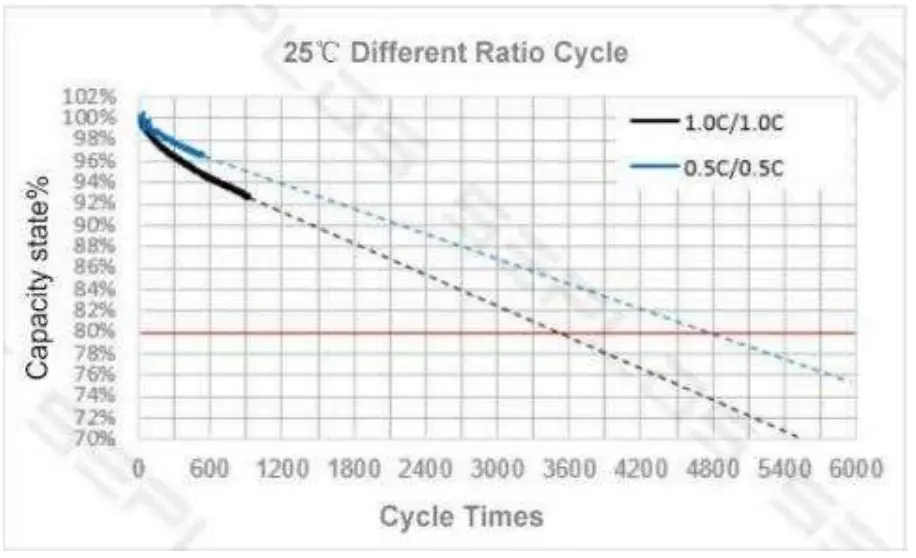
- The real capacity of each single cell is 105Ah.
- The module inside comes with 2 cells in parallel and 8 of those pairs in series.
Advanced Battery Management System (BMS) inside
The BMS is applied to monitor current, voltage, temperature, protection against over-charge, over-discharge, over-current, over-temperature, under-temperature and short circuit. The BMS provides cell balancing and current limitation during the charging process to ensure a reliable safety and performance.
The BMS will automatically adjust the Available capacity after every full charge of 56v when discharged.
This capacity will be influenced by the Temperature as the cells generally have less capacity available under very cold temperatures.
BMS Functions
- Over charge protection
- Over discharge protection
- Overcurrent protection
- Cell balancing
- Temperature protection
- CAN communication to inverters and RS485 communication between battery packs
Compatible Inverters (with regards to CANbus Communication), all other inverters should have the charge and discharge cut-off set with accordance to section 2.2 on the Manual
- Victron
- Growatt(Straight11145 cable to be used from the battery CAN port and the inverter CAN port)
- Goodwe(Straight RJ45 cable to be used from the battery CAN port and the inverter CAN port)
- Sunsynk(Straight RJ45 cable to be used from the battery CAN port and the inverter CAN port)
- Deye(Straight RJ45 cable to be used from the battery CAN port and the inverter CAN port)
Installation
When connecting the batteries in Parallel the batteries should be connected to a central Busbar and from the busbar be distributed to the inverters with equal cable lengths.
This document is subject to change without notice.
©2021 Lithium Batteries SA
617 Maretsel PI, Wychwood
Unit 9, The Gables Commercial Park
Johannesburg, 1401 TEL: (+27) 10 110 1991
mail: [email protected]
http://www.lbsa.co.za


