
MCO Home
9 in 1 MULTI-SENSOR
SKU: MCOEA8-9


Quickstart
This is a
secure
Alarm Sensor
for
Europe.
To run this device please connect it to your mains power supply.
To add this device to your network execute the following action:
1. Hold F1 to choose interface for Add or Remove Z-Wave network.
2. Click F2 five times until arrows icon turns blue
3. Hold F2 and the device enters into learning mode, then radio icon turns blue and the device is added into Z-Wave network.
Important safety information
Please read this manual carefully. Failure to follow the recommendations in this manual may be dangerous or may violate the law.
The manufacturer, importer, distributor and seller shall not be liable for any loss or damage resulting from failure to comply with the instructions in this manual or any other material.
Use this equipment only for its intended purpose. Follow the disposal instructions.
Do not dispose of electronic equipment or batteries in a fire or near open heat sources.
What is Z-Wave?
Z-Wave is the international wireless protocol for communication in the Smart Home. This
device is suited for use in the region mentioned in the Quickstart section.

Z-Wave ensures a reliable communication by reconfirming every message (two-way
communication) and every mains powered node can act as a repeater for other nodes
(meshed network) in case the receiver is not in direct wireless range of the
transmitter.
This device and every other certified Z-Wave device can be used together with any other
certified Z-Wave device regardless of brand and origin as long as both are suited for the
same frequency range.
If a device supports secure communication it will communicate with other devices
secure as long as this device provides the same or a higher level of security.
Otherwise it will automatically turn into a lower level of security to maintain
backward compatibility.
For more information about Z-Wave technology, devices, white papers etc. please refer
to www.z-wave.info.
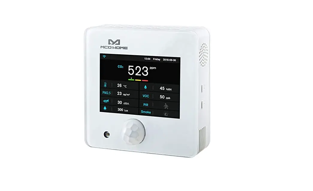
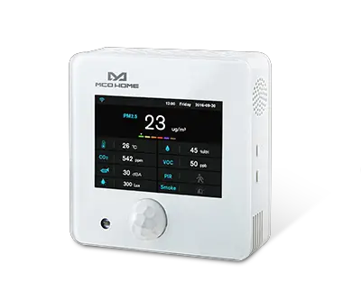
Product Description
MCOHome A8-9 is a Z-Wave enabled multiple environmental monitoring sensor, with 3.5 inch TFT clear display and compliant to Z-Wave Plus standard. It is built in with Temperature, Humidity, PM2.5, CO2, VOC, PIR, illumination, Noise, Smoke sensor. Device can be added into any Z-Wave network, and is compatible with any other Z-Wave certified devices.
Prepare for Installation / Reset
Please read the user manual before installing the product.
In order to include (add) a Z-Wave device to a network it must be in factory default
state. Please make sure to reset the device into factory default. You can do this by
performing an Exclusion operation as described below in the manual. Every Z-Wave
controller is able to perform this operation however it is recommended to use the primary
controller of the previous network to make sure the very device is excluded properly
from this network.
Reset to factory default
This device also allows to be reset without any involvement of a Z-Wave controller. This
procedure should only be used when the primary controller is inoperable.
1. Press & hold F1 to enter Z-Wave setting interface, then press & hold F1 again to enter parameters setting interface
2. Press & hold F2 to enter setting interface and select ““default””
3. Click F2 3 times and displays ““OFF””–>”“ON””–>”“OK””–>”“OFF””, factory setting is restored.
Safety Warning for Mains Powered Devices
ATTENTION: only authorized technicians under consideration of the country-specific
installation guidelines/norms may do works with mains power. Prior to the assembly of
the product, the voltage network has to be switched off and ensured against re-switching.
Installation
Device is suggested to be installed indoor, a place with around 1.5m height above the floor where represents the average CO2 concentration. It should be away from direct sunlight, any cover, or any heat source, to avoid false signal for temperature control.
1. Device must be wall-mounted vertically. Do not lay it flat or upside down while working.
2. Do not mount it in a wind gap, or cover its bottom, which may affect the detected data.
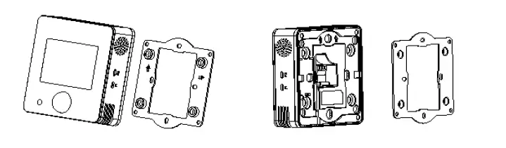
Step 1: Remove the steel frame from the backside of the device, and then fix it onto the installation box with 2 screws.
Step 2: Wire the adaptor.
Step 3: Put the device back onto the steel frame, it will attach with the frame firmly by built-in magnets.
Step 4: Check the installation and power, the device is ready for work.
Inclusion/Exclusion
On factory default the device does not belong to any Z-Wave network. The device needs
to be added to an existing wireless network to communicate with the devices of this network.
This process is called Inclusion.
Devices can also be removed from a network. This process is called Exclusion.
Both processes are initiated by the primary controller of the Z-Wave network. This
controller is turned into exclusion respective inclusion mode. Inclusion and Exclusion is
then performed doing a special manual action right on the device.
Inclusion
1. Hold F1 to choose interface for Add or Remove Z-Wave network.
2. Click F2 five times until arrows icon turns blue
3. Hold F2 and the device enters into learning mode, then radio icon turns blue and the device is added into Z-Wave network.
Exclusion
1. Hold F1 to choose interface for Add or Remove Z-Wave network.
2. Click F2 five times until arrows icon turns blue
3. Hold F2 and the device enters into learning mode, then radio icon turns blue and the device is removed into Z-Wave network.
Product Usage
Power on/off
Wire the adaptor and the device is powered on. It will display all detected information by the sensors.
Display interface
Hold Key F1 can switch among the following 4 display interfaces:
1. Data detecting: display all sensors”’ data
2. Network: Z-Wave Add/Remove
3. Data calibration: to calibrate the detected data manually
4. Local time setting
Data Calibration
1. Hold F1 to choose interface for data calibration.
2. Then hold F2 to switch among the sensors.
3. Choose one and click F2, F1 to change the data.
4. After finished, hold F1 can return data detecting interface.
Local time setting
1. Hold F1 to choose interface for local time setting.
2. Then hold F2 to switch among ““Hour-Minute-Second-Year-Month-Date””.
3. Click F2, F1 can change the data of flashing item.
4. After finished, hold F1 can return data detecting interface.
Quick trouble shooting
Here are a few hints for network installation if things dont work as expected.
- Make sure a device is in factory reset state before including. In doubt exclude before include.
- If inclusion still fails, check if both devices use the same frequency.
- Remove all dead devices from associations. Otherwise you will see severe delays.
- Never use sleeping battery devices without a central controller.
- Dont poll FLIRS devices.
- Make sure to have enough mains powered device to benefit from the meshing
Association – one device controls an other device
Z-Wave devices control other Z-Wave devices. The relationship between one device
controlling another device is called association. In order to control a different
device, the controlling device needs to maintain a list of devices that will receive
controlling commands. These lists are called association groups and they are always
related to certain events (e.g. button pressed, sensor triggers, …). In case
the event happens all devices stored in the respective association group will
receive the same wireless command wireless command, typically a ‘Basic Set’ Command.
Association Groups:
Group NumberMaximum NodesDescription
| 1 | 1 | Lifeline group |
Configuration Parameters
Z-Wave products are supposed to work out of the box after inclusion, however
certain configuration can adapt the function better to user needs or unlock further
enhanced features.
IMPORTANT: Controllers may only allow configuring
signed values. In order to set values in the range 128 … 255 the value sent in
the application shall be the desired value minus 256. For example: To set a
parameter to 200 it may be needed to set a value of 200 minus 256 = minus 56.
In case of a two byte value the same logic applies: Values greater than 32768 may
needed to be given as negative values too.
Parameter 1: PM2.5 Delta Level
This is the PM2.5 Delta Level which determine when to report the current PM2.5 value.
Size: 1 Byte, Default Value: 0
SettingDescription
| 0 | Indicates Turn off report |
| 1 – 127 | Indicates to report current PM2.5 value when change >n * 1ug/m3 |
Parameter 2: CO2 Delta Level
This is the CO2 Delta Level which determines when to report the current CO2 value.
Size: 1 Byte, Default Value: 0
SettingDescription
| 0 | Indicates Turn off report |
| 1 – 127 | Indicates to report current CO2 value when change > n * 5ppm |
Parameter 3: Temperature Delta Level
This is the temperature Delta Level which determines when to report the current temperature value.
Size: 1 Byte, Default Value: 0
SettingDescription
| 0 | Indicates Turn off report |
| 1 – 127 | Indicates to report current temperature value when change > n * 0.5 |
Parameter 4: Humidity Delta Level
This is the humidity Delta Level which determines when to report the current humidity value.
Size: 1 Byte, Default Value: 0
SettingDescription
| 0 | Indicates Turn off report |
| 1 – 127 | Indicates to report current humidity value when change >n% |
Parameter 5: VOC Delta Level
This is the VOC Delta Level which determines when to report the current VOC value.
Size: 1 Byte, Default Value: 0
SettingDescription
| 0 | Indicates Turn off report |
| 1 – 127 | n*5ppb Report change |
Parameter 6: Lux Delta Level
This is the brightness Delta Level which determines when to report the current brightness value.
Size: 2 Byte, Default Value: 0
SettingDescription
| 0 | Indicates Turn off report |
| 1 – 32767 | Indicates to report current Illumination value when change >n*1 Lux |
Parameter 7: dB Delta Level
This is the noise Delta Level which determines when to report the current noise value.
Size: 1 Byte, Default Value: 0
SettingDescription
| 0 | Indicates Turn off report |
| 1 – 127 | Indicates to report current Noise value when change >n*1 dB |
Parameter 8: PIR Delta Level
This is the temperature Delta Level which determines when to report the current temperature value.
Size: 1 Byte, Default Value: 0
SettingDescription
| 0 | Indicates Turn off report |
| 1 | Indicates report change |
Parameter 9: SMOKE Delta Level
Size: 1 Byte, Default Value: 1
SettingDescription
| 0 | Indicates Turn off report |
| 1 | Indicates report change |
Parameter 10: Smoke Timer
Size: 2 Byte, Default Value: 60
SettingDescription
| 0 | Turn off report |
| 35 – 32767 | Report every n*1s |
Parameter 11: PIR Timer
Size: 2 Byte, Default Value: 60
SettingDescription
| 0 | Turn off report |
| 35 – 32767 | Report every n*1s |
Parameter 12: PM2.5 Timer
Size: 2 Byte, Default Value: 120
SettingDescription
| 0 | Turn off report |
| 35 – 32767 | Report every n*1s |
Parameter 13: CO2 Timer
Size: 2 Byte, Default Value: 120
SettingDescription
| 0 | Turn off report |
| 35 – 32767 | Report every n*1s |
Parameter 14: Temperature Timer
Size: 2 Byte, Default Value: 180
SettingDescription
| 0 | Turn off report |
| 35 – 32767 | Report every n*1s |
Parameter 15: Humidity Timer
Size: 2 Byte, Default Value: 180
SettingDescription
| 0 | Turn off report |
| 35 – 32767 | Report every n*1s |
Parameter 16: VOC Timer
Size: 2 Byte, Default Value: 180
SettingDescription
| 0 | Turn off report |
| 35 – 32767 | Report every n*1s |
Parameter 17: LUX Timer
Size: 2 Byte, Default Value: 300
SettingDescription
| 0 | Turn off report |
| 35 – 32767 | Report every n*1s |
Parameter 18: db Timer
Size: 2 Byte, Default Value: 300
SettingDescription
| 0 | Turn off report |
| 35 – 32767 | Report every n*1s |
Parameter 47: Temperature unit
Size: 1 Byte, Default Value: 0
SettingDescription
| 0 | “°C |
| 1 | “°F |
Parameter 50: Temperature Offset
Size: 1 Byte, Default Value: 100
SettingDescription
| 0 – 127 | ((n-100)/10)=(-10~2.7)℃ |
| -128 (255) – -1 (128) | ((156+n)/10)=(2.8~15.5)℃ |
Parameter 51: Humidity Offset
Size: 2 Byte, Default Value: 20
SettingDescription
| 0 – 40 | n-20=(-20~20)% |
Parameter 52: CO2 OffSet
Size: 2 Byte, Default Value: 500
SettingDescription
| 0 – 1000 | (n-500)=(-500~500)ppm |
Parameter 53: PM2.5 Offset
Size: 1 Byte, Default Value: 100
SettingDescription
| 0 – 127 | n-100=(-100~27)ug/m3 |
| -128 (255) – -1 (128) | 156+n=(28~155)ug/m3 |
Parameter 54: Lux_OffSet
Size: 2 Byte, Default Value: 5000
SettingDescription
| 0 – 10000 | n-5000=(-5000~5000)lux |
Parameter 55: VOC Correct
Size: 1 Byte, Default Value: 100
SettingDescription
| 0 – 127 | n-100=(-100~27)ppb |
| -128 (255) – -1 (128) | 156+n=(28~155)ppb |
Parameter 65: dB Correct
Size: 1 Byte, Default Value: 50
SettingDescription
| 0 – 100 | (n-50)=-50~50 |
Parameter 255: Factory Reset (set only)
Size: 1 Byte, Default Value: 0
SettingDescription
| 85 | Factory Reset |
| 170 | Restore default Parameter |
Technical Data
| Dimensions | 0.1090000×0.1090000×0.0420000 mm |
| Weight | 404 gr |
| Hardware Platform | ZM5202 |
| EAN | 4251295702551 |
| IP Class | IP 20 |
| Voltage | 12 V |
| Device Type | Notification Sensor |
| Network Operation | Always On Slave |
| Z-Wave Version | 6.71.03 |
| Certification ID | ZC10-20096971 |
| Z-Wave Product Id | 0x015F.0xA803.0x135A |
| Color | White |
| Frequency | Europe – 868,4 Mhz |
| Maximum transmission power | 5 mW |
Supported Command Classes
- Association Grp Info
- Association V2
- Configuration
- Device Reset Locally
- Firmware Update Md V4
- Manufacturer Specific V2
- Powerlevel
- Security 2
- Sensor Multilevel V10
- Supervision
- Transport Service V2
- Version V2
- Zwaveplus Info V2
Explanation of Z-Wave specific terms
- Controller — is a Z-Wave device with capabilities to manage the network.
Controllers are typically Gateways,Remote Controls or battery operated wall controllers. - Slave — is a Z-Wave device without capabilities to manage the network.
Slaves can be sensors, actuators and even remote controls. - Primary Controller — is the central organizer of the network. It must be
a controller. There can be only one primary controller in a Z-Wave network. - Inclusion — is the process of adding new Z-Wave devices into a network.
- Exclusion — is the process of removing Z-Wave devices from the network.
- Association — is a control relationship between a controlling device and
a controlled device. - Wakeup Notification — is a special wireless message issued by a Z-Wave
device to announces that is able to communicate. - Node Information Frame — is a special wireless message issued by a
Z-Wave device to announce its capabilities and functions.


 Mcoemh8-fc Manual")