![]()
9 ln 1 Multi-Sensor
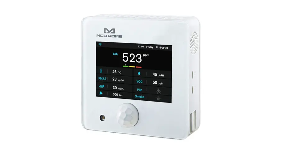
AS-9
MCOHome A8-9 is a Z-Wave Plus-enabled multiple environmental monitoring sensor, with 3.5 inches TFT clear display that can monitor the air quality in time. It is built-in with Temperature, Humidity, PM2.5, CO2, VOC, PIR, Illumination, Noise, Smoke sensor. The device can be added to any Z-Wave network and is compatible with any other Z-Wave-certified device.
- Temperature: 0~50 C
- Humidity: 0%RH~99%RH
- PM2.5: 0~500ug/m3
- C02: 0~5000ppm
- VOC: 0-64000ppb
- PIR: 0 or 1 Detection angle up to 120°
- Illumination: 0–40000 Lux
- Noise: 30dB~ IO0dB
- Smoke: 0or 1
Specification
- Power Supply: DC12V, 50/60Hz
- Self-Dissipation:<3W
- Work Environment:-20–+60 ·c <99%RH (Non-condensation)
- Dimension: 110* 110*32mm
- Hole Pitch: 60mm or 82mm
- Z-Wave Frequency: Operating frequency range, defined by the regulatory bodies {for Z-wave in Europe:
- 868.0 – 868.6 MHz, 869.7 – 870.0 MHz)
- Maximum Transmitting Power: +3dBm
- Housing: Tempered glass+ PC Alloy
- Installation: Wall-mounted (Vertical)

- Declaration of Conformity
 Hereby, MCOHome declares that the device is in compliance with the essential requirements and other relevant provisions of Directive 2014/53/EU .
 - WEEE Directive Compliance
 The device marked with this symbol should not be disposed of with household waste.lt is the user s responsibility to deliver the used appliance to a designated recycling point.
 - Z-Wave Compliance
 MCOHome sensor is a fully compatible Z-Wave Plus device.

Important Safety Instruction
![]() Read the instructions before starting up the unit!
Read the instructions before starting up the unit!![]() This product is not a toy. Keep out ofreach of children and animals!
This product is not a toy. Keep out ofreach of children and animals!![]() Do not expose the device to moisture, water or other liquids.
Do not expose the device to moisture, water or other liquids.![]() Do not place liquids near or on the device! Do not attempt to disassemble, repair or modify the device yourself
Do not place liquids near or on the device! Do not attempt to disassemble, repair or modify the device yourself![]() This product is for indoor use only. Do not use outdoors!
This product is for indoor use only. Do not use outdoors!
![]() CAUTIONS!
CAUTIONS!
Flush-mount only into a UL/ETL/CE certified plastic junction box. The minimum size should be 65*65*45mm, minimum Volume is 190cm3. Use Copper Conductors Only.
![]() CAUTIONS!
CAUTIONS!
Risk of Electric Shock – More than one disconnect switch may be required to de-energize the equipment before servicing.
Installation& Wiring
To protect yourself and others from danger and to protect the device from damage, please read the safety information before using it.
![]() Important!
Important!
- A qualified electrician with an understanding of wiring diagrams and knowledge of electrical safety should complete installation following the instructions.
- Before installation, please confirm the real voltage complies with the device’s specification. Cut off an.y power supply to secure the safety of people and device.
- During installation, protect the device from any physical damage by dropping or bumping. If happens, please contact the supplier for maintenance.
- Keep the device away from acid-base and other corrosive solids, liquids, gases, to avoid damage.
- Avoid overexertion during operation, to protect the device from mechanical damage.
- Read all instructions and documentation and save for future reference.
Location:
The device is suggested to be installed indoor, a place with around 1.5m height above the floor. It should be away from direct sunlight, an.y cover, or any heat source, to avoid false signal for temperature control.
Notice!
- Device must be wall-mounted vertically. Do not lay it fiat or upside down while working.
- Do not mount it in a wind gap, or cover its bottom, which may affect the detected data.
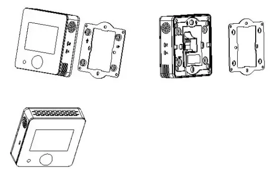
Step 1:Remove the steel frame from the backside of the device, and then fix it onto the installation box with 2 screws.
Step 2: Wire the adaptor.
Step 3:Put the device back onto the steel frame, it will attach with the frame finnly by built-in magnets.
Step 4:Check the installation and power, the device is ready for work.
Operation
Power On/Off
Wire the adaptor and the device is powered on. It will display all detected information by the sensors.
Display Interface
Hold Key Fl can switch among the following 4 display interfaces:
- Data detecting: display all sensors’ data
- Network: Z-Wave Add/Remove
- Parameter setting: e.g. data calibration, temp. format, restore default parameters, etc
- Local time setting
Z-Wave Operation
Note: A Security Enabled Z-Wave Controller must be used in order to Jully utilize the product
- Add &Remove the Z-Wave network
►Activate Add/Remove mode in the gateway. When the device is powered on, hold Fl to choose an interface for Add or Remove Z-Wave network.
► Click F2 five times until C turns blue.
► Hold F2 and the device enter into learning mode, then turns blue and the device is added to the Z-Wave network.
► Follow the same step to remove the device from the network. - Association Group
The device supports 1 association group:
AG Identifier | Max Node ID | Command Class | Trigger Situation |
| Ox01 | 1 | COMMAND CLASS —SENSO | The detected value will be reported according to: 1,PM2.5 The value difference between current value and previous reported value > the setting value of parameter number 1, set value#0; |
AG Identifier | Max Node ID | Command Class | Trigger Situation |
| COMMAND CLASS DEVICE RESET LOCALLY, DEVICE RESET LOCALLY NOTIFICATION | Factory setting restored |
Command Class Supported By The Device: ( Support S2 unauthenticated level)
COMMAND _ CLASS_ VERSION,
COMMAND _ CLASS _MANUFACTURER_ SPECIFIC,
COMMAND_CLASS_DEVICE_RESET_LOCALLY,
COMMAND _ CLASS _pOWERLEVEL,
COMMAND_CLASS_ASSOCIATION,
COMMAND _ CLASS _ASSOCIATION_ GRP _ INFO,
COMMAND_CLASS_CONFIGURATION,
COMMAND _ CLASS _ SENSOR _ MULTILEVEL,
COMMAND_CLASS_FIRMWARE_UPDATE_MD
Command Class Supported By The Device: (Not support S2)
COMMAND_CLASS_ZWAVEPLUS_INFO,
COMMAND _ CLASS_ TRANSPORT _SERVICE_ V2,
COMMAND _ CLASS _ SECURITY _ 2,
COMMAND_CLASS_SUPERVISION
Restore Factory Setting
- Press & hold Fl to enter Z-Wave setting interface, then press & hold Fl again to enter parameters setting interface;
- Press & hold F2 to enter setting interface and select “default”;
- Click F2 3 limes and displays “OFF”–>”ON”–>”OK”–>”OFF”, factory setting is restored.
Data Calibration
Hold Fl to choose an interface for data calibration. Tuen hold F2 to switch among the sensors. Choose one and click F2, FI to change the data. After finish«!, hold FI can return data detecting interface.
Local Time Setting
Hold F 1 to choose an interface for local time setting. Then hold F2 to switch among “Hour-Minute-Second-Year-Month-Date”. Click F2, Fl can change the data offlashing item. After finished, hold F 1 can return data detecting interface.
The Main Sensor Display Setting (Default sensor is CO2)
Enter the parameter setting interface, long press F2 to select parameter number “O”, name “DPI”, then short press F2 to select CO2 or PM2.5, long press FI to confirm exit.
Parameter Table
| Number | Name | Size | Description | Default | Possible value |
| 1 | PM25DeltaLevel | 1 | =0 Turn off report >=1 Report when change > n * lug/m3 | 0 | 0-127 |
| 2 | CO2DeltaLevel | 1 | =0 Turn off report >=1 Report when change >n * 5ppm | 0 | 0-127 |
| 3 | Temp_Delta_Level | 1 | report =0 Turn off rep >=1 Report when change >n*0.5 C | 0 | 0-127 |
| 4 | Humidity_Delta_Level | 1 | report =0 Turn off rep >=1 Report when change >n% | 0 | 0-127 |
| 5 | VOCDeltaLevel | 1 | =0 Turn off report >=1-127*5ppb Report change | 0 | 0-127 |
| 6 | LuxDeltaLevel | =0 Turn report off rep >=1 Report when change >n* 1 Lux | 0 | 0-32767 | |
| 7 | dBDeltaLevel | 1 | =0 Turn off report >=1 Report when change >n*ldB | 0 | 0-127 |
| 8 | PIRDeltaLevel | 1 | =0 Turn off report =1 Report change | 0 | 0-1 |
| 9 | SMOICE_Delta_Level | 1 | =0 Turn off report =1 Report change | 1 | 0-1 |
Number | Name | Size | Description | Default | Possible value |
| 10 | Smoke_Timer | 2 | Turn off report >= 35 Report every n*ls interval | 60 | 0,35-32767 |
| 11 | P1RTimer _ | 2 | Turn off report >=35 Report every n* Is interval | 60 | 0,35-32767 |
| 12 | PM25 Timer | 2 | Turn off report >=35Report every n*ls interval | 120 | 0,35-32767 |
| 13 | CO2_Timer | 2 | =0 Turn off report* >=35 Report every n Is interval | 0,35-32767 | |
| 14 | Temp_Timer | 2 | =0 Turn off report >=35 Report every n* Is interval | 180 | 0,35-32767 |
| 15 | Humidity_Timer | 2 | =0 Turn off report* =35 Report every n1 s interval | 0,35-32767 | |
| 16 | VOC_Timer | 2 | Turn off report >=35 Report every n*ls interval | 180 | 0,35-32767 |
| 17 | Lux_Timer | 2 | =0 Turn off report* >=35 Report every nls interval | 0,35-32767 | |
| 18 | dB_Timer | 2 | =0 Turn off report* >=35 Report every nIs interval | 0,35-32767 | |
| 47 | Temp. Unit | 1 | =0 C =1 7 | 0 | 0-1 |
| 50 | T_OffSet | 1 | 0 – 127:((n-100)/10)=(-10-2.7)C -128 – -1:((156+W/10)-(2.8-15.5)C | 100 | -128-127 |
| 51 | RH_OffSet | 1 | n-20=(-20-20)% | 20 | 0-40 |
| 52 | CO2_OffSet | 2 | (n-500)-(-500-500)ppm | 500 | 0-1000 |
| 53 | PM2.5 OffSet | 1 | 0 – 127:n-100=(-100-27)ug/m3 -128 – -1:156+n=(28-155)ug/m3 | 100 | -128-127 |
| 54 | Lux_OfiSet | 2 | n-5000=(-5000-5000)1ux | 5000 | 0-10000 |
| 55 | VOC_Correct | 1 | 0 – 127:n-100=(-100–27)ppb -128 – -1:156+n-(28-155)ppb | 100 | -128-127 |
| 56 | dB Correct | I | (n-50)=-50-50 | 50 | 0-100 |
| 255 | Write Only | 1 | 85: Restore factory setting 170: Restore default parameters. | 0 | 85,170 |
1-Year Limited Warranty
MCOHome warrants this product to be free from defects in material and workmanship under normal and proper use for one year from the purchase date of the original purchaser. MCOHome will, at its option, either repair or replace any part of its products that prove defective by reason of improper workmanship or materials.
THIS LIMITED WARRANTY DOES NOT COVER ANY DAMAGE TO THIS PRODUCT THAT RESULTS FROM IMPROPER INSTALLATION, ACCIDENT, ABUSE, MISUSE, NATURAL DISASTER, INSUFFICIENT OR EXCESSIVE ELECTRICAL SUPPLY, ABNORMAL MECHANICAL OR ENVIRONMENTAL CONDITIONS, OR ANY UNAUTHORIZED DISASSEMBLY, REPAIR, OR MODIFICATION.
This limited warranty shall not apply if: (i) the product was not used in accordance with any accompanying instructions, or (ii) the product was not used for its intended function. This limited warranty also does not apply to any product on which the original identification information has been altered, obliterated, or removed, that has not been handled or packaged correctly, that has been soldas second-band or that has been resold contrary to Country and other applicable export regulations.


