![]() LiFeP04 Battery System for Households
LiFeP04 Battery System for Households
User Guide
ABOUT THIS MANUAL
1.1 Purpose
This manual describes the introduction, installation, operation and emergency situations of the battery bank.
Please read this manual carefully before installations and operations. Keep this manual for future reference.
1.2 Scope
This manual provides safety and installation guidelines as well as information on tools and wiring.
1.3 Safety Instructions![]() WARNING: This chapter contains important safety and operating instructions. Read and keep this (‘manual for future reference.
WARNING: This chapter contains important safety and operating instructions. Read and keep this (‘manual for future reference.
- Before using the unit, read all instructions and cautionary markings on the unit, the batteries and all appropriate sections of this manual.
- CAUTION — To reduce risk of injury,damage,even burst. please use it following using manual. In case of causing personal
- Do not disassemble the battery. Take it to a qualified service center when service or repair is required.
Incorrect re-assembly may result in a risk of fire. - To reduce risk of electric shock, disconnect all wirings before attempting any maintenance or cleaning.
Turning off the unit will not reduce this risk. - CAUTION – Only qualified personnel can install this device with inverter.
- For optimum operation of this battery, please follow required spec to select appropriate cable size.
- Be very cautious when working with metal tools on or around batteries. A potential risk exists to drop a tool to spark or short circuit batteries or other electrical parts and could cause an explosion or fire.
- Please strictly follow installation procedure.
- To support full output load, at least 2 sets of LPBF48V for inverter larger than 6KVA in parallel connection.
- GROUNDING INSTRUCTIONS – This System should be connected to a permanent grounded wiring system. Be sure to comply with local requirements.
- NEVER cause AC output and DC input short circuited. Do not connect to the mains when DC input short circuits.
- Warning!! Only qualified service persons are able to service this device.
- Battery should be installed indoor and kept away from water, high temperature mechanical force and flames.
- Do not install the battery in any environment of temperature below0C or over 55°C,and humidity over 80%.
- Do not put any heavy objects on the battery.
1.4 Can be connected in parallel
- The batteries can be connected in parallel. Series connection is not allowed.
Use in upright position only. - The batteries are not allowed to connected with PWM controller for charging.
Special Attention: Due to the built-in protection board of the lithium battery pack is with over-discharge protection function, it is strongly recommended to stop using the load when the battery pack is over-discharged. The battery pack cannot be repeatedly activated for discharge. Or the battery may be failed to be activated by the AC or PV activation cable ( It requires a special charging activation method), so cannot be charged. Therefore, when the battery pack is low power, please charge the battery as soon as possible when main power or solar energy is available.
INTRODUCTION
The battery system main using Solar power system for Family house. It also have a with to controller the battery easily and protect our Household application timely.
2. 1 Features
- Iron phosphate-lithium power battery
- Long warranty period:5 years
- Higher energy density, smaller volumn for household.
- Support connected in parallel mode for expansion
- Photovoltaic system: This battery pack is designed for household photovoltaic systems.
- Battery management system (BMS): The battery packs built-in BMS monitors its operation and prevents the battery from operating outside design limitations.
- Expandability: This battery pack can be easily expanded by adding expansion battery packs in parallel connection.
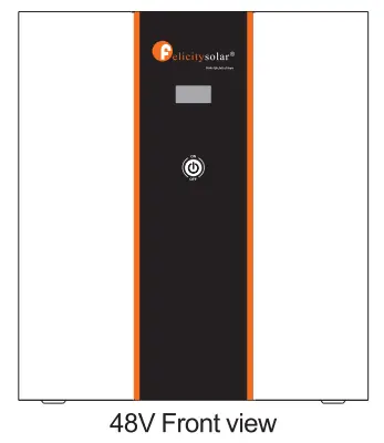
2.2 Product Over View
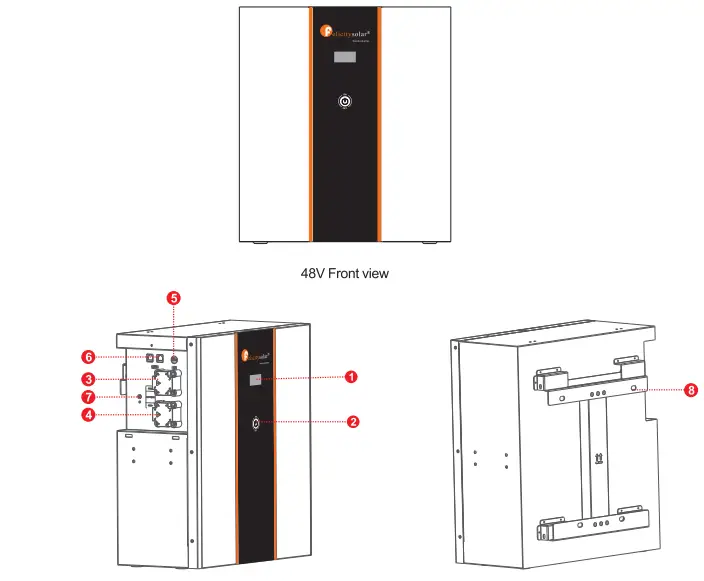
- LCD display
- Power On/Charging indicator
- Battery Negative –
- Battery Positive+
- Switch
- Communication port 7.Earth wire
- Wall mounted fixing
2.3 Specifications
| Model | LP8F4820-L | 1.128F48200-N |
| Usable Capacity | 8.7KWH | IOKWH |
| Nominal Voltage | 51. | 51. |
| Voltage Range | 48.57.6 | 48.57.6 |
| MAX. Charge & Discharge Current | 120A030.5 | 120A©30.6 |
| Recommend Charge 8 Discharge Current | 580A | 580A |
| MAX. Output Power | 6000W | 6000W |
| Recommend Output Power | 4000W | 4000W |
| DOD | 295% | |
| Modules Connection | 1-6in parallel | |
| Communication | CAN&RS485 | |
| Ingress Protection | IP21 | |
| Cycle Life | 60000251C, 80%DOD | |
| Working Temperature Range | Discharge:-20°C to +65°C, Charge:+0°C to +55°C | |
| Net Weight(KG) | 65KG | MG |
| Gross Weight(KG) | 80KG | MG |
| Product Dimension(MM) | 5204602511161 | sttr46cr2s2Mm |
| Package Dimension(MM) | 815•555•41011M | 815•556,110MM |
2.4 Recommended Settings
Lithium battery pack is not same as lead-acid battery, so for the devices which you connect with the battery pack for charging or discharging, such as inverters, MPPT charger controllers or UPS, please implement pre-settings as recommended settings as below before you launched them.
| Setting | LPBF443200-L | LP8F48200-m |
| Max. Charging Voltage | 57.6V | 57.6V |
| Floating charging Voltage | 57.6V | 57.6V |
| Max. Charging Current | 80/04 | 80A’N |
| Cut-off voltage | 48V | 48V |
Notes: “N” means the number of battery packs connected in parallel.
INSTALLATION
3. 1 Unpacking and Inspection
Before installation, please inspect the unit. Be sure that nothing inside the package is damaged. You should have received the following items inside of package.
| NO | NAME | SPECIFICATION | PICTURE |
| 1 | Wall mount | Wall mount bracket | 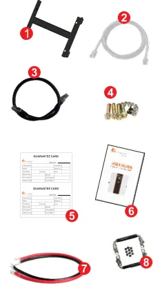 |
| 2 | Communication line 1 | Used for communication between battery and PCS | |
| 3 | Communication line 2 | Used for Communication among batteries | |
| 4 | Saew | Mounting screw | |
| 5 | User manual | User manual | |
| 6 | Guarantee card | Guarantee card | |
| 7 | Cables | Used for battery parallel connection | |
| 8 | Handle | Handle |
3.2 Mounting the Unit
Consider the following points before selecting where to install:
- Do not mount the battery on flammable construction materials.
- The ambient temperature should be between 0°C and 45’C to ensure optimal operation.
- The recommended installation position is to be adhered to the wall vertically.
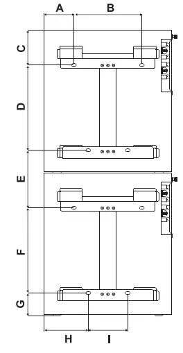
- Be sure to keep other objects and surfaces as shown in the right diagram to guarantee sufficient heat dissipation and to have enough space for removing wires.
| LPBF48200-L | I LPBF48200-N | |
| A | 110 | |
| B | 240 | |
| C | 131 | |
| D | 301 | |
| E | 223 | |
| F | 301 | |
| G | 88 | |
| H | 160 | |
| I | 140 | |
Please follow below steps to implement battery connection:
- Assemble battery ring terminal based on recommended battery cable and terminal size.
- Connect all battery packs as units requires. It’s suggested to connect at least 2 sets of LPBF48V for inverter larger than 7.5KVA in parallel connection.
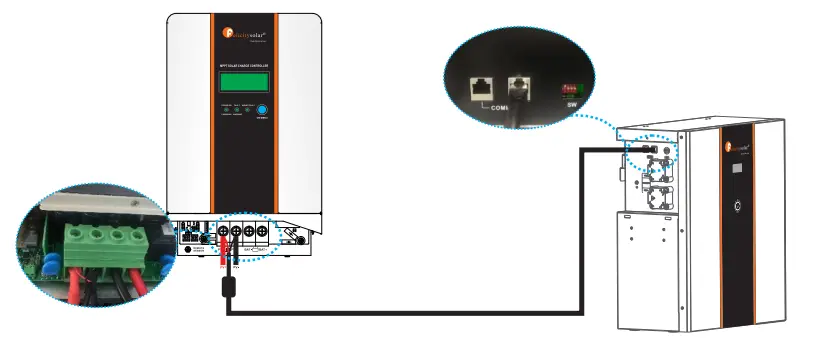
Note: if you need the battery wake-up when the grid back, connect the battery with grid use power adapter and communication line 1 shown in the package list.
3.3 Connection for Parallel Mode
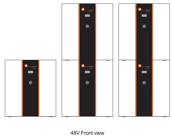
The eStrong LPBF series battery support to be connected in parallel for expansion. If you need one more battery bank work in parallel mode, connect the battery as shown in PIC 2
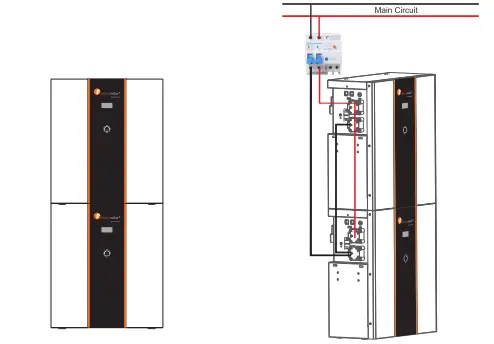
Step 1 : The batteries are placed as shown in Figure 1
Step 2: The schematic diagram of the parallel connection of two battery packs is shown in Figure 2.
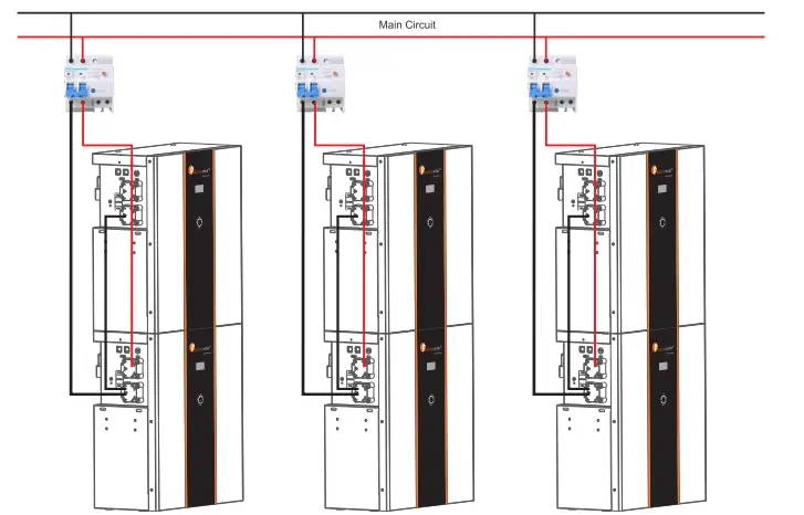
Step 3: The schematic diagram of the parallel connection of six battery packs is shown in Figure 3.
Note: After completing the above 4 steps, arbitrarily select the positive and negative poles of one of the battery packs to output (the upper battery pack or the lower battery pack. you can not select the positive and negative poles of the two battery packs at the same time). After confirming the correct connection of the inverter, controller and battery, you can turn on any of the switches and use the battery group happily
Note: One group of LPBF48V can be stacked up to 2 layers, and up to 6 in parallel connection.
For pure off grid system ,the PV awake wire need to be connected with MPPT charge controller if the battery pack is charged by solar panels only. The connection diagram as below:
OPERATION
Once the batteries are connected well, simply press On/Off button to enable the output of the battery pack.
4. 1 Switch On I Off
- Switch on: press On/Off button to switch on the battery, then the battery will do self-inspection before enable output.
- Switch off: press and hold On/Off button for 3 seconds, the battery will shut down directly.
Description for Communication port
| Picture | PIN | Description |
 | 1 | Trigger-GND |
| 2 | Trigger-VCC | |
| 3 | NC | |
| 4 | COMM-GND | |
| 5 | RS485-B | |
| 6 | RS485-A | |
| 7 | CANL | |
| 8 | CANH |
| DIP SWITCH | ||
 | 1-4 | Communication Address |
| 5 | Termination Resister | |
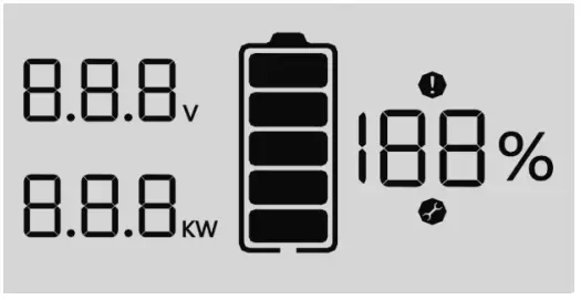
4.2 LCD Display icons
 | |
| Icon | Function description |
| Display Information | |
 | Indicates battery voltage. |
 | Indicates battery power. |
 | Indicate SOC. |
| Battery Information | |
 | Indicates battery level by 0-19%,20-39%, 40-59%, 60-79%and 80-100%. (When charging, this icon is displayed for horse running; hendischarging, the icon displays constant). |
| Fault information | |
| Indicates a fault. | |
| set information | |
| Indicates settings. | |
4.3 BMS information Page
The basic information will be displayed in turn after power on.
BMS power on information BMS information is all on. 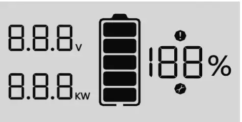 | BMS address / version Eg: “AO1″is the dial address; 410” is the software version; “4” is the countdown.  |
BMS type Eg: BMS model is 48200″3″ is the countdown.  | BMS charge voltage I current Eg: “57.6V” / “80A” refers to charging cut-off voltage and charging limit current, “2” is the countdown.  |
BMS discharge voltage / current Eg: “48.0V”/”80A” refers to discharging cut-off voltage and discharging limit current, “1” is the countdown.  | BMS data Eg: “52.0V”/”3.90KW”/”70%” refers to battery voltage. power and SOC. 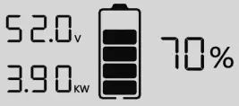 |
| BMS fault code / flag Eg:”52.0V” / “C09” / “70%” are battery voltage, fault code and SOC respectively, and Fault icon constant. 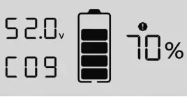 |
4.4 Fault Code Table
| Fault Code | Fault information | Trouble Shooting |
| C01 | Battery overvoltage ove | Restart the unit, if the error happens again, please return to repair center. |
| CO2 | unde Battery undervoltage | Restart the unit, if the error happens again, please return to repair center. |
| CO3 | Single cell overvoltage | Restart the unit, if the error happens again, please return to repair center. |
| C04 | Single cell undervoltage | Restart the unit, if the error happens again, please return to repair center. |
| CO5 | charge overcu Battery overcurrent | Restart the unit, if the error happens again, please return to repair center. |
| C06 | discharge overcu Battery overcurrent | Restart the unit, if the error happens again, please return to repair center. |
| C07 | MOS tube overtemperature | 1 .The inner temperature is over the limitation. 2. Check whether theambient temperature is too high. |
| CO8 | MOS tube undertemperature | 1.The internal temperature is lower than the limit range. 2.Check whether the ambient temperature is too low. |
| C09 | Single cell ovetemperature | Restart the unit, if the error happens again, please return to repair center. |
| C10 | Single cell undertemperature | Restart the unit, if the error happens again, please return to repair center. |
| C11 | Abnormal current sampling | Restart the unit, if the error happens again, please return to repair center. |
| C12 | Abnormal output impedance | Restart the unit, if the error happens again, please return to repair center. |
| C13 | Parallel failed | 1.Please check if single unit is installed to parallel system. 2.If this error happens during parallel installation, please check wires connectiotn. If they are connected correctly, please funish parallel installation first, and t hen Restart the unit. 3.If the problem remains, please contact your installer. |
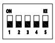
4.5 DIP switch SW1-SW4 Description
| DIP switch SW1-SW4 Description | ||||||
| Sw1 | SW2 | SW3 | SW4 | Remarks | DIP switch SW5 Desaiption | |
| 0 | 0 | 0 | 0 | means ID=0,communication address is0x00/0x10 | SW5 | Remarks |
| 1 | 0 | 0 | 0 | means ID=1,communication address is0x01 | 1 | means connect 1200 resistor |
| 0 | 1 | 0 | 0 | means ID=2,communication address is0x02 | ||
| 1 | 1 | 0 | 0 | means ID=3,communication address is0x03 | 0 | means disconnect 1200 resistor |
| 0 | 0 | 1 | 0 | means ID=4,communication address is0x04 | ||
| 1 | 0 | 1 | 0 | means ID=5,communication address is0x05 | ||
| 0 | 1 | 1 | 0 | means ID=6,communication address is0x06 | ||
| 1 | 1 | 1 | 0 | means ID=7,communication address is0x07 | ||
| 0 | 0 | 0 | 1 | means ID=8,communication address is0x08 | ||
| 1 | 0 | 0 | 1 | means ID=9,communication address is0x09 | ||
| 0 | 1 | 0 | 1 | means ID=10,communication address is0x0A | ||
| 1 | 1 | 0 | 1 | means ID=11,communication address is0x0B | ||
| 0 | 0 | 1 | 1 | means ID=12,communication address is0x0C | ||
| 1 | 0 | 1 | 1 | means ID=13,communication address is0x0D | ||
| 0 | 1 | 1 | 1 | means ID=14,communication address is0x0E | ||
| 1 | 1 | 1 | 1 | means ID=15,communication address is0x0F | ||
| Remark : 1 in SW1-SW5 indicates ON status, and 0 indicates OFF status. | ||||||
| Remark : When multiple battery packs communicate, the last battery pack SW5 needs to be in the ON status, otherwise the communication may have interference. | ||||||
| Remark : When the battery pack ID is set to 0, it means stand-alone operation, and it is not necessary to detect whether the parallel condition is satisfied . | ||||||
| Remark : When the battery pack ID is set to 1-15, it means that the parallel operation is required, and it is necessary to detect whether the parallel condition is satisfied | ||||||
| Remark : The parallel condition is that the difference between the battery voltage of the local battery and all the battery pack voltages is CV, otherwise wait until the condition is satisfied | ||||||
EMERGENCY SITUATIONS
Felicity cannot guarantee eStrong battery absolute safety.
5.1 Fire
In case of fires, make sure that the following equipment is available near the system.
- SCBA (self-contained breathing apparatus) and protective gear in compliance with the Directive on Personal Protective Equipment 89/686/EEC.
- NOVEC 1230, FM-200, or dioxide extinguisher Batteries may explode when heated above 150C. KEEP FARAWAY from the battery if it catches fire.
5.2 Leaking Batteries
If the battery pack leaks electrolyte, avoid contact with the leaking liquid or gas. If one is exposed the leaked substance, immediately perform the cations described below.
- Inhalation: Evacuate the contaminated area, and seek medical attention.
- Contact with eyes: Rinse eyes with running water for 5 minutes, and seek medical attention.
- Contact with skin: Wash the affected area thoroughly with soap and water, and seek medical attention.
- Ingestion: Induce vomiting, and seek medical attention.
5.3 Wet Batteries
If the battery pack is wet or submerged in water, do not let people access it, and contact your supplier for help.
Damaged Batteries
Damaged batteries are not fit for use and are dangerous and must be handled with the utmost care. It may leak electrolyte or produce flammable gas. If the battery pack seems to be damaged, pack it in its original container, and then return it to your supplier.
5.4 Warranty
Products that are operated strictly in accordance with the user manual are covered by the warranty. Any violation of this manual may void the warranty.
Limitation of Liability
Any product damage or property loss caused by the following conditions, Felicity does not assume any direct or indirect liability.
Product modified, design changed or parts replaced.
- Changed, or attempted repairs and erasing of series number or seals;
- System design and installation are not in compliance with standards and regulations;
- The product has been improperly stored in end user’s premises;
- Transport damage (including painting scratch caused by movement inside packaging during shipping). A claim should be made directly to shipping or insurance company.
![]()


