intel BCH IP Core
About the BCH IP Core
Related Information
- BCH IP Core Document Archive on page 24
- Provides a list of user guides for previous versions of the BCH IP Core.
- Introduction to Intel FPGA IP Cores
- Provides general information about all Intel FPGA IP cores, including parameterizing, generating, upgrading, and simulating IP cores.
- Creating Version-Independent IP and Qsys Simulation Scripts
- Create simulation scripts that do not require manual updates for software or IP version upgrades.
- Project Management Best Practices
- Guidelines for efficient management and portability of your project and IP files.
Intel® DSP IP Core Features
- Avalon® Streaming (Avalon-ST) interfaces
- DSP Builder for Intel® FPGAs ready
- Testbenches to verify the IP core
- IP functional simulation models for use in Intel-supported VHDL and Verilog HDL simulators
BCH IP Core Features
- High-performance fully parameterizable encoder or decoder for error detection and correction:
- Number of symbols per codeword
- Number of check symbols per codeword
- Number of parallel input bits
Intel Corporation. All rights reserved. Intel, the Intel logo, and other Intel marks are trademarks of Intel Corporation or its subsidiaries. Intel warrants the performance of its FPGA and semiconductor products to current specifications in accordance with Intel’s standard warranty but reserves the right to make changes to any products and services at any time without notice. Intel assumes no responsibility or liability arising out of the application or use of any information, product, or service described herein except as expressly agreed to in writing by Intel. Intel customers are advised to obtain the latest version of device specifications before relying on any published information and before placing orders for products or services.
- Other names and brands may be claimed as the property of others.
DSP IP Core Device Family Support
Intel offers the following device support levels for Intel FPGA IP cores:
- Advance support—the IP core is available for simulation and compilation for this device family. FPGA programming file (.pof) support is not available for Quartus Prime Pro Stratix 10 Edition Beta software and as such IP timing closure cannot be guaranteed. Timing models include initial engineering estimates of delays based on early post-layout information. The timing models are subject to change as silicon testing improves the correlation between the actual silicon and the timing models. You can use this IP core for system architecture and resource utilization studies, simulation, pinout, system latency assessments, basic timing assessments (pipeline budgeting), and I/O transfer strategy (data-path width, burst depth, I/O standards tradeoffs).
- Preliminary support—Intel verifies the IP core with preliminary timing models for this device family. The IP core meets all functional requirements, but might still be undergoing timing analysis for the device family. You can use it in production designs with caution.
- Final support—Intel verifies the IP core with final timing models for this device family. The IP core meets all functional and timing requirements for the device family. You can use it in production designs.
Table 1. DSP IP Core Device Family Support
| Device Family | Support |
| Arria® II GX | Final |
| Arria II GZ | Final |
| Arria V | Final |
| Intel Arria 10 | Final |
| Cyclone® IV | Final |
| Cyclone V | Final |
| Intel Cyclone 10 | Final |
| Intel MAX® 10 FPGA | Final |
| Stratix® IV GT | Final |
| Stratix IV GX/E | Final |
| Stratix V | Final |
| Intel Stratix 10 | Advance |
| Other device families | No support |
BCH IP Core Release Information
Use the release information when licensing the IP core.
Table 2.Release Information
| Item | Description |
| Version | 17.1 |
| Release Date | Novermber 2017 |
| Ordering Code | IP-BCH (IPR-BCH) |
Intel verifies that the current version of the Quartus Prime software compiles the previous version of each IP core. Intel does not verify that the Quartus Prime software compiles IP core versions older than the previous version. The Intel FPGA IP Release Notes lists any exceptions.
Related Information
- Intel FPGA IP Release Notes
- Errata for BCH IP core in the Knowledge Base
DSP IP Core Verification
- Before releasing a version of an IP core, Intel runs comprehensive regression tests to verify its quality and correctness. Intel generates custom variations of the IP core to exercise the various parameter options and thoroughly simulates the resulting simulation models with the results verified against master simulation models.
BCH IP Core Performance and Resource Utilization
- Typically expected performance for a BCH IP Core using the Quartus Prime software with the Arria V (5AGXFB3H4F35C5), Cyclone V (5CGXFC7C7F23C8), and Stratix V (5SGXEA7H3F35C3) devices. Where m is the number of bits per symbol; n is the codeword length; d is the parallel data input width; t is the error correction capability.
Table 3. Decoder Performance and Resource Utilization
| Device | Parameters | Memory | ALM | Registers | max (MHz) | |||||
| m | n | d | t | M10K | M20K | Primary | Secondary y | |||
| Arria V | 8 | 255 | 10 | 42 | 7 | — | 18,376 | 40,557 | 3,441 | 196 |
| Cyclone V | 8 | 255 | 10 | 42 | 7 | — | 18,264 | 40,709 | 3,266 | 150 |
| Stratix V | 8 | 255 | 10 | 42 | — | 7 | 19,027 | 44,134 | 4,315 | 308 |
| Arria V | 8 | 255 | 12 | 42 | 9 | — | 22,293 | 49,602 | 4,053 | 186 |
| Cyclone V | 8 | 255 | 12 | 42 | 9 | — | 22,243 | 49,243 | 4,511 | 149 |
| Stratix V | 8 | 255 | 12 | 42 | — | 8 | 23,187 | 53,800 | 5,207 | 310 |
| Arria V | 8 | 255 | 2 | 42 | 4 | — | 5,539 | 13,238 | 788 | 207 |
| Cyclone V | 8 | 255 | 2 | 42 | 4 | — | 5,527 | 13,174 | 857 | 174 |
| Stratix V | 8 | 255 | 2 | 42 | — | 4 | 6,088 | 14,399 | 850 | 369 |
| Arria V | 8 | 255 | 5 | 42 | 5 | — | 10,231 | 23,321 | 1,554 | 206 |
| Cyclone V | 8 | 255 | 5 | 42 | 5 | — | 10,234 | 23,391 | 1,551 | 164 |
| continued… | ||||||||||
| Device | Parameters | Memory | ALM | Registers | max (MHz) | |||||
| m | n | d | t | M10K | M20K | Primary | Secondary y | |||
| Stratix V | 8 | 255 | 5 | 42 | — | 5 | 10,820 | 24,868 | 2,612 | 335 |
| Stratix V | 14 | 8784 | 10 | 20 | — | 18 | 7,358 | 15,082 | 761 | 346 |
| Stratix V | 14 | 8784 | 10 | 40 | — | 18 | 14,331 | 28,743 | 1,630 | 316 |
| Stratix V | 14 | 8784 | 10 | 80 | — | 18 | 28,383 | 56,292 | 3,165 | 281 |
| Stratix V | 14 | 8784 | 20 | 20 | — | 18 | 10,103 | 19,833 | 933 | 323 |
| Stratix V | 14 | 8784 | 20 | 40 | — | 18 | 20,012 | 37,413 | 1,747 | 304 |
| Stratix V | 14 | 8784 | 20 | 80 | — | 18 | 39,225 | 72,151 | 3,673 | 282 |
| Stratix V | 14 | 8784 | 30 | 20 | — | 17 | 11,784 | 23,924 | 844 | 329 |
| Stratix V | 14 | 8784 | 30 | 40 | — | 19 | 23,061 | 44,313 | 1,836 | 289 |
| Stratix V | 14 | 8784 | 30 | 80 | — | 19 | 43,949 | 85,476 | 3,398 | 263 |
| Stratix V | 14 | 8784 | 40 | 20 | — | 19 | 13,801 | 28,032 | 743 | 307 |
| Stratix V | 14 | 8784 | 40 | 40 | — | 19 | 26,107 | 51,680 | 1,472 | 291 |
| Stratix V | 14 | 8784 | 40 | 80 | — | 21 | 50,303 | 98,545 | 3,351 | 248 |
| Stratix V | 14 | 8784 | 50 | 20 | — | 20 | 16,407 | 33,020 | 967 | 307 |
| Stratix V | 14 | 8784 | 50 | 40 | — | 20 | 31,095 | 60,503 | 1,991 | 288 |
| Stratix V | 14 | 8784 | 50 | 80 | — | 22 | 58,690 | 116,232 | 3,222 | 249 |
| Stratix V | 14 | 8784 | 60 | 20 | — | 20 | 18,290 | 37,106 | 914 | 297 |
| Stratix V | 14 | 8784 | 60 | 40 | — | 20 | 35,041 | 67,183 | 2,324 | 292 |
| Stratix V | 14 | 8784 | 60 | 80 | — | 37 | 80,961 | 160,458 | 7,358 | 233 |
| Stratix V | 14 | 8784 | 70 | 20 | — | 20 | 20,494 | 41,471 | 545 | 286 |
| Stratix V | 14 | 8784 | 70 | 40 | — | 20 | 38,294 | 74,727 | 1,778 | 280 |
| Stratix V | 14 | 8784 | 70 | 80 | — | 38 | 88,040 | 173,311 | 7,769 | 232 |
| Stratix V | 14 | 8784 | 80 | 20 | — | 22 | 22,437 | 45,334 | 691 | 276 |
| Stratix V | 14 | 8784 | 80 | 40 | — | 22 | 42,256 | 82,173 | 1,363 | 285 |
| Stratix V | 14 | 8784 | 80 | 80 | — | 40 | 95,913 | 186,869 | 7,317 | 229 |
Table 4. Encoder Performance and Resource Utilization
| Device | Parameters | Memory | ALM | Registers | max (MHz) | |||||
| m | n | d | t | M10K | M20K | Primary | Secondary y | |||
| Arria V | 8 | 255 | 10 | 42 | 2 | — | 337 | 592 | 0 | 243 |
| Cyclone V | 8 | 255 | 10 | 42 | 2 | — | 339 | 592 | 0 | 166 |
| Stratix V | 8 | 255 | 10 | 42 | — | 1 | 353 | 601 | 3 | 400 |
| Arria V | 8 | 255 | 12 | 42 | 2 | — | 386 | 602 | 0 | 257 |
| Cyclone V | 8 | 255 | 12 | 42 | 2 | — | 395 | 602 | 0 | 174 |
| continued… | ||||||||||
| Device | Parameters | Memory | ALM | Registers | max (MHz) | |||||
| m | n | d | t | M10K | M20K | Primary | Secondary y | |||
| Stratix V | 8 | 255 | 12 | 42 | — | 1 | 391 | 614 | 0 | 400 |
| Arria V | 8 | 255 | 2 | 42 | 2 | — | 219 | 547 | 12 | 275 |
| Cyclone V | 8 | 255 | 2 | 42 | 2 | — | 219 | 556 | 3 | 197 |
| Stratix V | 8 | 255 | 2 | 42 | — | 2 | 220 | 542 | 17 | 464 |
| Arria V | 8 | 255 | 5 | 42 | 2 | — | 237 | 563 | 3 | 276 |
| Cyclone V | 8 | 255 | 5 | 42 | 2 | — | 237 | 565 | 1 | 193 |
| Stratix V | 8 | 255 | 5 | 42 | — | 1 | 260 | 573 | 0 | 400 |
| Stratix V | 14 | 8784 | 10 | 20 | — | 3 | 400 | 785 | 4 | 387 |
| Stratix V | 14 | 8784 | 10 | 40 | — | 3 | 613 | 1,348 | 1 | 380 |
| Stratix V | 14 | 8784 | 10 | 80 | — | 3 | 1,009 | 2,451 | 4 | 309 |
| Stratix V | 14 | 8784 | 20 | 20 | — | 3 | 775 | 849 | 1 | 373 |
| Stratix V | 14 | 8784 | 20 | 40 | — | 3 | 1,340 | 1,410 | 0 | 312 |
| Stratix V | 14 | 8784 | 20 | 80 | — | 3 | 2,222 | 2,515 | 1 | 242 |
| Stratix V | 14 | 8784 | 30 | 20 | — | 3 | 1,161 | 919 | 1 | 324. |
| Stratix V | 14 | 8784 | 30 | 40 | — | 3 | 2,074 | 1,480 | 0 | 253 |
| Stratix V | 14 | 8784 | 30 | 80 | — | 3 | 3,583 | 2,580 | 2 | 224 |
| Stratix V | 14 | 8784 | 40 | 20 | — | 3 | 1,522 | 977 | 4 | 307 |
| Stratix V | 14 | 8784 | 40 | 40 | — | 3 | 2,789 | 1,541 | 0 | 249 |
| Stratix V | 14 | 8784 | 40 | 80 | — | 3 | 4,909 | 2,647 | 0 | 191 |
| Stratix V | 14 | 8784 | 50 | 20 | — | 4 | 1,926 | 1,042 | 9 | 295 |
| Stratix V | 14 | 8784 | 50 | 40 | — | 4 | 3,467 | 1,610 | 1 | 234 |
| Stratix V | 14 | 8784 | 50 | 80 | — | 4 | 6,297 | 2,714 | 3 | 182 |
| Stratix V | 14 | 8784 | 60 | 20 | — | 4 | 2,356 | 1,121 | 0 | 266 |
| Stratix V | 14 | 8784 | 60 | 40 | — | 4 | 3,824 | 1,680 | 1 | 229 |
| Stratix V | 14 | 8784 | 60 | 80 | — | 4 | 7,548 | 2,783 | 0 | 167 |
| Stratix V | 14 | 8784 | 70 | 20 | — | 4 | 2,595 | 1,184 | 2 | 273 |
| Stratix V | 14 | 8784 | 70 | 40 | — | 4 | 4,372 | 1,746 | 0 | 221 |
| Stratix V | 14 | 8784 | 70 | 80 | — | 4 | 8,321 | 2,850 | 2 | 169 |
| Stratix V | 14 | 8784 | 80 | 20 | — | 5 | 2,885 | 1,251 | 1 | 293 |
| Stratix V | 14 | 8784 | 80 | 40 | — | 5 | 5,163 | 1,812 | 0 | 220 |
| Stratix V | 14 | 8784 | 80 | 80 | — | 5 | 8,867 | 2,918 | 0 | 169 |
BCH IP Core Getting Started
Installing and Licensing Intel FPGA IP Cores
The Intel Quartus® Prime software installation includes the Intel FPGA IP library. This library provides many useful IP cores for your production use without the need for an additional license. Some Intel FPGA IP cores require the purchase of a separate license for production use. The Intel FPGA IP Evaluation Mode allows you to evaluate these licensed Intel FPGA IP cores in simulation and hardware, before deciding to purchase a full production IP core license. You only need to purchase a full production license for licensed Intel IP cores after you complete hardware testing and are ready to use the IP in production. The Intel Quartus Prime software installs IP cores in the following locations by default:
Figure 1. IP Core Installation Path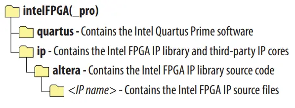
Table 5. IP Core Installation Locations
| Location | Software | Platform |
| <drive>:\intelFPGA_pro\quartus\ip\altera | Intel Quartus Prime Pro Edition | Windows* |
| <drive>:\intelFPGA\quartus\ip\altera | Intel Quartus Prime Standard Edition | Windows |
| <home directory>:/intelFPGA_pro/Quartus/IP/Altera | Intel Quartus Prime Pro Edition | Linux* |
| <home directory>:/inter FPGA/Quartus/IP/Altera | Intel Quartus Prime Standard Edition | Linux |
Intel FPGA IP Evaluation Mode
The free Intel FPGA IP Evaluation Mode allows you to evaluate licensed Intel FPGA IP cores in simulation and hardware before purchase. Intel FPGA IP Evaluation Mode supports the following evaluations without an additional license:
- Simulate the behavior of a licensed Intel FPGA IP core in your system.
- Verify the functionality, size, and speed of the IP core quickly and easily.
- Generate time-limited device programming files for designs that include IP cores.
- Program a device with your IP core and verify your design in hardware.
Intel Corporation. All rights reserved. Intel, the Intel logo, and other Intel marks are trademarks of Intel Corporation or its subsidiaries. Intel warrants performance of its FPGA and semiconductor products to current specifications in accordance with Intel’s standard warranty, but reserves the right to make changes to any products and services at any time without notice. Intel assumes no responsibility or liability arising out of the application or use of any information, product, or service described herein except as expressly agreed to in writing by Intel. Intel customers are advised to obtain the latest version of device specifications before relying on any published information and before placing orders for products or services.
- Other names and brands may be claimed as the property of others.
Intel FPGA IP Evaluation Mode supports the following operation modes:
- Tethered—Allows running the design containing the licensed Intel FPGA IP indefinitely with a connection between your board and the host computer. Tethered mode requires a serial joint test action group (JTAG) cable connected between the JTAG port on your board and the host computer, which is running the Intel Quartus Prime Programmer for the duration of the hardware evaluation period. The Programmer only requires a minimum installation of the Intel Quartus Prime software, and requires no Intel Quartus Prime license. The host computer controls the evaluation time by sending a periodic signal to the device via the JTAG port. If all licensed IP cores in the design support tethered mode, the evaluation time runs until any IP core evaluation expires. If all of the IP cores support unlimited evaluation time, the device does not time-out.
- Untethered—Allows running the design containing the licensed IP for a limited time. The IP core reverts to untethered mode if the device disconnects from the host computer running the Intel Quartus Prime software. The IP core also reverts to untethered mode if any other licensed IP core in the design does not support tethered mode.
When the evaluation time expires for any licensed Intel FPGA IP in the design, the design stops functioning. All IP cores that use the Intel FPGA IP Evaluation Mode time out simultaneously when any IP core in the design times out. When the evaluation time expires, you must reprogram the FPGA device before continuing hardware verification. To extend use of the IP core for production, purchase a full production license for the IP core.
You must purchase the license and generate a full production license key before you can generate an unrestricted device programming file. During Intel FPGA IP Evaluation Mode, the Compiler only generates a time-limited device programming file (<project name>_time_limited.sof) that expires at the time limit.
Figure 2. Intel FPGA IP Evaluation Mode Flow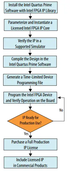
Note:
Refer to each IP core’s user guide for parameterization steps and implementation details.
Intel licenses IP cores on a per-seat, perpetual basis. The license fee includes first-year maintenance and support. You must renew the maintenance contract to receive updates, bug fixes, and technical support beyond the first year. You must purchase a full production license for Intel FPGA IP cores that require a production license, before generating programming files that you may use for an unlimited time. During Intel FPGA IP Evaluation Mode, the Compiler only generates a time-limited device programming file (<project name>_time_limited.sof) that expires at the time limit. To obtain your production license keys, visit the Self-Service Licensing Center or contact your local Intel FPGA representative.
The Intel FPGA Software License Agreements govern the installation and use of licensed IP cores, the Intel Quartus Prime design software, and all unlicensed IP cores.
- Intel Quartus Prime Licensing Site
- Intel FPGA Software Installation and Licensing
BCH IP Core Intel FPGA IP Evaluation Mode Timeout Behavior
All IP cores in a device time out simultaneously when the most restrictive evaluation time is reached. If a design has more than one IP core, the time-out behavior of the other IP cores may mask the time-out behavior of a specific IP core. For IP cores, the untethered time-out is 1 hour; the tethered time-out value is indefinite. Your design stops working after the hardware evaluation time expires. The Quartus Prime software uses Intel FPGA IP Evaluation Mode Files (.ocp) in your project directory to identify your use of the Intel FPGA IP Evaluation Mode evaluation program. After you activate the feature, do not delete these files.When the evaluation time expires, the data output port data_out goes low
Related Information
AN 320: OpenCore Plus Evaluation of Megafunctions
Catalog and Parameter Editor
The IP Catalog displays the IP cores available for your project. Use the following features of the IP Catalog to locate and customize an IP core:
- Filter IP Catalog to Show IP for active device family or Show IP for all device families. If you have no project open, select the Device Family in IP Catalog.
- Type in the Search field to locate any full or partial IP core name in IP Catalog.
- Right-click an IP core name in IP Catalog to display details about supported devices, to open the IP core’s installation folder, and for links to IP documentation.
- Click Search for Partner IP to access partner IP information on the web.
- The parameter editor prompts you to specify an IP variation name, optional ports, and output file generation options. The parameter editor generates a top-level Intel Quartus Prime IP file (.ip) for an IP variation in Intel Quartus Prime Pro Edition projects.
- The parameter editor generates a top-level Quartus IP file (.qip) for an IP variation in Intel Quartus Prime Standard Edition projects. These files represent the IP variation in the project and store parameterization information.
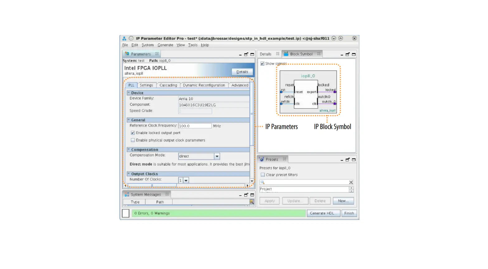
Figure 3. IP Parameter Editor (Intel Quartus Prime Pro Edition)
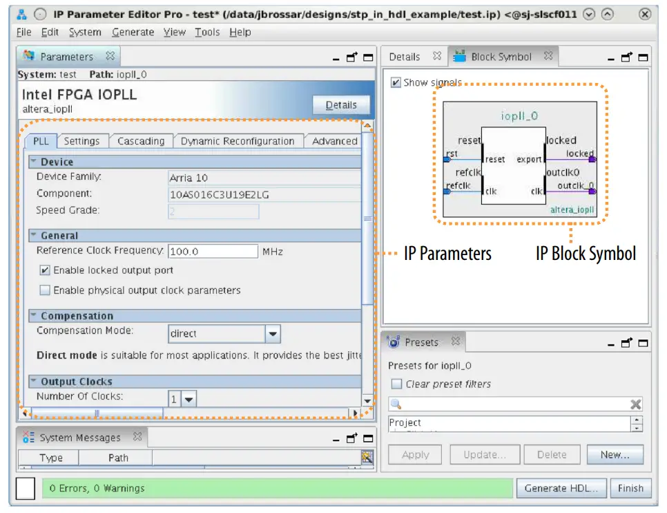
Figure 4. IP Parameter Editor (Intel Quartus Prime Standard Edition)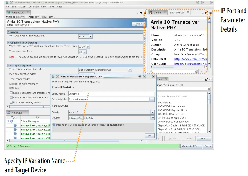
Generating IP Cores (Intel Quartus Prime Pro Edition)
Quickly configure Intel FPGA IP cores in the Intel Quartus Prime parameter editor. Double-click any component in the IP Catalog to launch the parameter editor. The parameter editor allows you to define a custom variation of the IP core. The parameter editor generates the IP variation synthesis and optional simulation files and
adds
the .ip file representing the variation to your project automatically.
Figure 5. IP Parameter Editor (Intel Quartus Prime Pro Edition)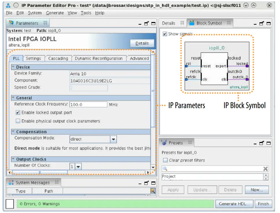
Follow these steps to locate, instantiate, and customize an IP core in the parameter editor:
- Create or open an Intel Quartus Prime project (.qpf) to contain the instantiated IP variation.
- In the IP Catalog (Tools ➤ IP Catalog), locate and double-click the name of the IP core to customize. To locate a specific component, type some or all of the component’s name in the IP Catalog search box. The New IP Variation window appears.
- Specify a top-level name for your custom IP variation. Do not include spaces in IP variation names or paths. The parameter editor saves the IP variation settings in a file named <your_ip>.ip. Click OK. The parameter editor appears.
- Set the parameter values in the parameter editor and view the block diagram for the component. The Parameterization Messages tab at the bottom displays any errors in IP parameters:
- Optionally, select preset parameter values if provided for your IP core. Presets specify initial parameter values for specific applications.
- Specify parameters defining the IP core functionality, port configurations, and device-specific features.
- Specify options for processing the IP core files in other EDA tools.
- Note: Refer to your IP core user guide for information about specific IP core parameters.
- Click Generate HDL. The Generation dialog box appears.
- Specify output file generation options, and then click Generate. The synthesis and simulation files generate according to your specifications.
- To generate a simulation testbench, click Generate ➤ Generate Testbench System. Specify testbench generation options, and then click Generate.
- To generate an HDL instantiation template that you can copy and paste into your text editor, click Generate ➤ Show Instantiation Template.
- Click Finish. Click Yes if prompted to add files representing the IP variation to your project.
- After generating and instantiating your IP variation, make appropriate pin assignments to connect ports.
Note: Some IP cores generate different HDL implementations according to the IP core parameters. The underlying RTL of these IP cores contains a unique hash code that prevents module name collisions between different variations of the IP core. This unique code remains consistent, given the same IP settings and software version during IP generation. This unique code can change if you edit the IP core’s parameters or upgrade the IP core version. To avoid dependency on these unique codes in your simulation environment, refer to Generating a Combined Simulator Setup Script.
IP Core Generation Output (Intel Quartus Prime Pro Edition)
The Intel Quartus Prime software generates the following output file structure for individual IP cores that are not part of a Platform Designer system.
Figure 6. Individual IP Core Generation Output (Intel Quartus Prime Pro Edition)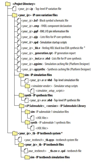
- If supported and enabled for your IP core variation.
Table 6. Output Files of Intel FPGA IP Generation
| File Name | Description |
| <your_ip>.ip | Top-level IP variation file that contains the parameterization of an IP core in your project. If the IP variation is part of a Platform Designer system, the parameter editor also generates a .qsys file. |
| <your_ip>.cmp | The VHDL Component Declaration (.cmp) file is a text file that contains local generic and port definitions that you use in VHDL design files. |
| <your_ip>_generation.rpt | IP or Platform Designer generation log file. Displays a summary of the messages during IP generation. |
| continued… | |
| File Name | Description |
| <your_ip>.qgsimc (Platform Designer systems only) | Simulation caching file that compares the .qsys and .ip files with the current parameterization of the Platform Designer system and IP core. This comparison determines if Platform Designer can skip the regeneration of the HDL. |
| <your_ip>.qgsynth (Platform Designer systems only) | Synthesis caching file that compares the .qsys and .ip files with the current parameterization of the Platform Designer system and IP core. This comparison determines if Platform Designer can skip the regeneration of the HDL. |
| <your_ip>.qip | Contains all information to integrate and compile the IP component. |
| <your_ip>.csv | Contains information about the upgrade status of the IP component. |
| <your_ip>.bsf | A symbolic representation of the IP variation for use in Block Diagram Files (.bdf). |
| <your_ip>.spd | Input file that ip-make-simscript requires to generate simulation scripts. The .spd file contains a list of files you generate for simulation, along with information about memories that you initialize. |
| <your_ip>.ppf | The Pin Planner File (.ppf) stores the port and node assignments for IP components you create for use with the Pin Planner. |
| <your_ip>_bb.v | Use the Verilog BlackBox (_bb. v) file as an empty module declaration for use as a black box. |
| <your_ip>_inst.v or _inst.vhd | HDL example instantiation template. Copy and paste the contents of this file into your HDL file to instantiate the IP variation. |
| <your_ip>.regmap | If the IP contains register information, the Intel Quartus Prime software generates the .regmap file. The .regmap file describes the register map information of master and slave interfaces. This file complements the .sopcinfo file by providing more detailed register information about the system. This file enables register display views and user-customizable statistics in System Console. |
| <your_ip>.svd | Allows HPS System Debug tools to view the register maps of peripherals that connect to HPS within a Platform Designer system. During synthesis, the Intel Quartus Prime software stores the .svd files for the slave interface visible to the System Console masters in the .sof file in the debug session. The system Console reads this section, which Platform Designer queries for register map information. For system slaves, the Platform Designer accesses the registers by name. |
| <your_ip>.v <your_ip>.vhd | HDL files that instantiate each submodule or child IP core for synthesis or simulation. |
| mentor/ | Contains a msim_setup.TCL script to set up and run a ModelSim simulation. |
| aldec/ | Contains a Riviera*-PRO script rivierapro_setup. TCL to setup and run a simulation. |
| /synopsys/vcs /synopsys/vcsmx | Contains a shell script vcs_setup.sh to set up and run a VCS* simulation. Contains a shell script vcsmx_setup.sh and synopsys_sim.setup file to set up and run a VCS MX* simulation. |
| /cadence | Contains a shell script ncsim_setup.sh and other setup files to set up and run an NCSIM simulation. |
| /submodules | Contains HDL files for the IP core submodule. |
| <IP submodule>/ | Platform Designer generates /synth and /sim sub-directories for each IP submodule directory that Platform Designer generates. |
Simulating Intel FPGA IP Cores
The Intel Quartus Prime software supports IP core RTL simulation in specific EDA simulators. IP generation creates simulation files, including the functional simulation model, any testbench (or example design), and vendor-specific simulator setup scripts for each IP core. Use the functional simulation model and any testbench or example design for simulation. IP generation output may also include scripts to compile and run any testbench. The scripts list all models or libraries you require to simulate your IP core.
The Intel Quartus Prime software provides integration with many simulators and supports multiple simulation flows, including your own scripted and custom simulation flows. Whichever flow you choose, IP core simulation involves the following steps:
- Generate simulation model, testbench (or example design), and simulator setup script files.
- Set up your simulator environment and any simulation scripts.
- Compile simulation model libraries.
- Run your simulator.
DSP Builder for Intel FPGAs Design Flow
DSP Builder for Intel FPGAs shortens digital signal processing (DSP) design cycles by helping you create the hardware representation of a DSP design in an algorithm-friendly development environment.
This IP core supports DSP Builder for Intel FPGAs. Use the DSP Builder for Intel FPGAs flow if you want to create a DSP Builder for Intel FPGAs model that includes an IP core variation; use IP Catalog if you want to create an IP core variation that you can instantiate manually in your design.
Related Information
Using MegaCore Functions chapter in the DSP Builder for Intel FPGAs Handbook.
BCH IP Core Functional Description
This topic describes the IP core’s architecture, interfaces, and signals.
You can parameterize the BCH IP core as an encoder or a decoder. The encoder receives data packets and generates the check symbols; the decoder detects and corrects errors.
BCH IP Core Encoder
The BCH encoder has a parallel architecture with input and output of d data bits. When the encoder receives data symbols, it generates check symbols for a given codeword and sends the input codeword with the check symbols to the output interface. The encoder uses backpressure on the upstream component when it generates the check symbols.
Figure 7. Encoder Timing
The ready signal indicates that the encoder can accept incoming stream. On the clk rising edge, if the encoder ready signal is high, send input data stream via data_in port and assert load high to indicate valid input data. Assume the full message word needs X clock signals. When this input process reaches X-1 clock cycles, the encoder ready signal goes low. At the next clk rising edge, the encoder accepts the input from data_in port, and the encoder receives the full message word. Before the ready signal returns to high again, the encoder does not accept new input data. When valid_outt signal is asserted high, output encoded codeword is valid at the data_out port. At the first clock cycle where the output data is valid, sop_out is asserted high for only one cycle, indicating the start of packet. The IP core has forward and back pressure, which you can control with the ready and sink_ready signal. Assert the sop_in and eop_in signals correctly at the clock cycle, i.e. the first and last clock cycle of the input codeword.
Shortened Codewords
The BCH IP core supports shortened codewords. A shortened codeword contains fewer symbols than the maximum value of N, which is 2M –1, where N is the total number of symbols per codeword and M is the number of bits per symbol. A shortened codeword is mathematically equivalent to a maximum-length code with the extra data symbols at the start of the codeword set to 0. For example, (220,136) is a shortened codeword of (255,171). Both of these codewords use the same number of check symbols, 11. To use shortened codewords with the decoder, use the parameter editor to set the codeword length to the correct value.
BCH IP Core Decoder
When the decoder receives the encoded codeword, it uses the check symbols to detect errors and correct them. The received encoded codeword may differ from the original codeword because of noise in the channel. The decoder detects errors using several polynomials to locate the error location and the error value. When the decoder obtains the error location and value, the decoder corrects the errors in a codeword and sends the codeword to the output. If e<=t, the IP core can correct errors; if e > t, you see unpredictable results.
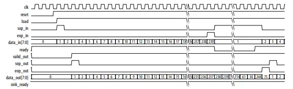
Figure 8. Decoder Timing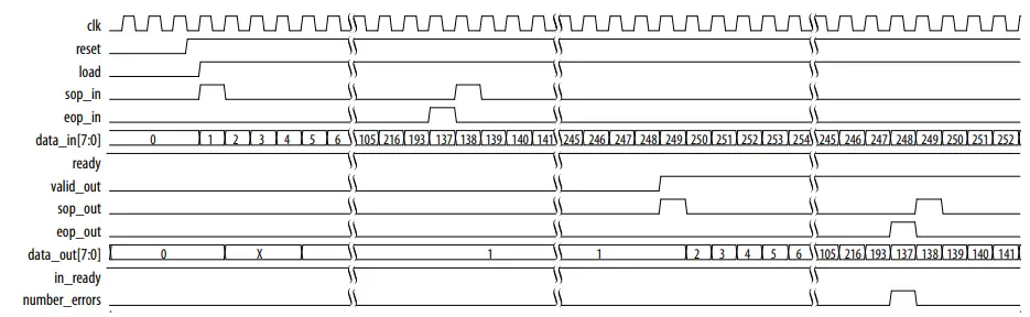
The codeword starts when you assert the load signal and the sop_in signal.The decoder accepts the data at data_in as valid data. The codeword ends when you assert the eop_in signal. For a 1-channel codeword, assert the sop_in and eop_in signals for one clock cycle. When the decoder deasserts the ready signal, the decoder cannot process any more data until it asserts the ready signal again. At the output, the operation is identical. When the decoder asserts the valid_out signal and the sop_out signal, the decoder provides valid data on data_out. The decoder asserts the sop_out signal and the eop_out signal to indicate the start and end of a codeword. The decoder automatically detects and corrects errors in a codeword and asserts the number_of_errors signal when it encounters a non-correctable codeword. The decoder outputs the full codeword including the check symbols, which you should remove. The ready signal indicates that the decoder can accept an incoming stream. On clk rising edge, if the encoder ready signal is high, send input data stream via data_in and assert load high to indicate valid input data. When valid_out is asserted high, the output decoded word is valid at the data_out port. The number_of_errors shows the number of errors the IP core detects. At the first clock cycle where the output data is valid, sop_out is asserted high for only one cycle, indicating the start of output packet. The IP core has forward and back pressure, which you controll with the ready signal and sink_ready signal. Assert the sop_in and eop_in signals correctly at the clock cycle, i.e. the first and last clock cycle of the input codeword.
CH IP Core Parameters
Table 7. Parameters
| Parameter | Legal Values | Default Value | Description |
| BCH module | Encoder or Decoder | Encoder | Specify an encoder or a decoder. |
| Number of bits per symbol (m) | 3 to 14 (encoder or 6 to 14 (decoder) | 14 | Specify the number of bits per symbol. |
| Codeword length (n) | parity_bits+1 : 2m-1 | 8,784 | Specify the codeword length. The decoder accepts a new symbol every clock cycle if 6.5R < N. If N>=6.5R +1, the decoder shows continuous behavior. |
| Error correction capacity (t) | Range derived from m. For the decoder, the wizard caps the range between 8 and 127. | 40 | Specify the number of bits to be corrected. |
| Parity bits | – | 560 | Shows the number of parity bits in the codeword. The wizard derives this parameter from t. |
| Message length (k) | – | 8,224 | Shows the number of message bits in the codeword. The wizard derives this parameter from t and n. |
| Primitive polynomial | – | 17,475 | Shows the primitive polynomial. derived from the choice of m. |
| Parallel input data width | Encoder: 1 to min(parity_bits, k-1). Decoder: • d < floor(n*3/14) • d < floor(n/ floor[2*log2(2*t)]) | 20 | The number of bits to input every clock cycle. |
BCH IP Core Interfaces and Signals
Table 8. Clock and Reset Signals
| Name | Avalon-ST Type | Direction | Description |
| CLK | CLK | Input | The main system clock. The whole IP core operates on the rising edge of CLK. |
| reset | reset_n | Input | An active low signal that resets the entire system when asserted. You can assert this signal asynchronously. However, you must deassert it synchronously to the clk_clk signal. When the IP core recovers from reset, ensure that the data it receives is a complete packet. |
Table 9. Avalon-ST Input and Output Interface Signals
| Name | Avalon-ST Type | Direction | Description |
| ready | ready | Output | Data transfer ready signal to indicate that the sink is ready to accept data. The sink interface drives the ready signal to control the flow of data across the interface. The sink interface captures the data interface signals on the current clk rising edge. |
| data_in[] | data | Input | Data input for each codeword, symbol by symbol. Valid only when you assert the in_valid signal. |
| data_out | data | Output | Contains decoded output when the IP core asserts the out_valid signal. The corrected symbols are in the same order that they are entered. |
| eop_in | eop | Input | End of packet (codeword) signal. |
| eop_out | eop | Output | End of packet (codeword) signal. This signal indicates the packet boundaries on the data_in[] bus. When the IP core drives this signal high, it indicates that the end of packet is present on the data_in[] bus. The IP core asserts this signal on the last transfer of every packet. |
| in_error | error | Input | Error signal. Specifies if the input data symbol is an error and whether the decoder can consider it as an erasure. Erasures-supporting decoders only. |
| load | valid | Input | Data valid signal to indicate the validity of the data signals. When you assert the in_valid signal, the Avalon-ST data interface signals are valid. When you deassert the in_valid signal, the Avalon-ST data interface signals are invalid and must be disregarded. You can assert the in_valid signal whenever data is available. However, the sink only captures the data from the source when the IP core asserts the in_ready signal. |
| number_of_err ors | error | Output | Indicates the number of errors (decoder only). Valid when the IP core asserts eop_out . |
| sop_in | sop | Input | Start of packet (codeword) signal. |
| sop_out | sop | Output | Start of packet (codeword) signal. This signal indicates the codeword boundaries on the data_in[] bus. When the IP core drives this signal high, it indicates that the start of packet is present on the data_in[] bus. The IP core asserts this signal on the first transfer of every codeword. |
| sink_ready | ready | Input | Data transfer ready signal to indicate that the downstream module is ready to accept data. The source provides new data (if available) when you assert the sink_ready signal and stops providing new data when you deassert the sink_ready signal. If the source is unable to provide new data, it deasserts valid_out for one or more clock cycles until it is prepared to drive valid data interface signals. |
| valid_out | valid | Output | Data valid signal. The IP core asserts the valid_out signal high, whenever a valid output is on data_out ; the IP core deasserts the signal when there is no valid output on data_out . |
For IP cores generated within Qsys, all signals are in an Avalon-ST interface. For encoders:
- Input: in[0 to data width of data_in]
- Output: out[0 to data width of data_out].
For decoders:
- Input: in[0 to data width of data_in]
- Output: out [0 to data width+number_errors | data_out]
Avalon-ST Interfaces in DSP IP Cores
Avalon-ST interfaces define a standard, flexible, and modular protocol for data transfers from a source interface to a sink interface.
The input interface is an Avalon-ST sink and the output interface is an Avalon-ST source. The Avalon-ST interface supports packet transfers with packets interleaved across multiple channels.
Avalon-ST interface signals can describe traditional streaming interfaces supporting a single stream of data without knowledge of channels or packet boundaries. Such interfaces typically contain data, ready, and valid signals. Avalon-ST interfaces can also support more complex protocols for burst and packet transfers with packets interleaved across multiple channels. The Avalon-ST interface inherently synchronizes multichannel designs, which allows you to achieve efficient, time-multiplexed implementations without having to implement complex control logic.
Avalon-ST interfaces support backpressure, which is a flow control mechanism where a sink can signal to a source to stop sending data. The sink typically uses backpressure to stop the flow of data when its FIFO buffers are full or when it has congestion on its output.
Related Information
Avalon Interface Specifications
Document Revision History
BCH IP Core User Guide revision history.
| Date | Version | Changes |
| 2017.11.06 | 17.1 | • Added support for Intel Cyclone 10 devices • Corrected signal names in encoder and decoder descriptions. |
| 2017.02.14 | 16.1 | • Removed product ID and vendor ID. • Corrected Error correction capability (t) max value to 127 |
| 2015.10.01 | 15.1 | Added product ID and ordering code. |
| 2015.05.01 | 15.0 | Initial release |
Intel Corporation. All rights reserved. Intel, the Intel logo, and other Intel marks are trademarks of Intel Corporation or its subsidiaries. Intel warrants performance of its FPGA and semiconductor products to current specifications in accordance with Intel’s standard warranty, but reserves the right to make changes to any products and services at any time without notice. Intel assumes no responsibility or liability arising out of the application or use of any information, product, or service described herein except as expressly agreed to in writing by Intel. Intel customers are advised to obtain the latest version of device specifications before relying on any published information and before placing orders for products or services.
- Other names and brands may be claimed as the property of others.
A. BCH IP Core Document Archive
If the table does not list an IP core version, the user guide for the previous IP core version applies.
| IP Core Version | User Guide |
| 16.1 | BCH IP Core User Guide |
| 15.1 | BCH IP Core User Guide |
References
 End User License Agreements
-
Intel® FPGAs and Programmable Devices-Intel® FPGA
-
FPGA Knowledge Base Articles Search
-
PSG Documentation
-
Intel Shapes the Future of Technology
-
1. About the BCH IP Core
-
1. Answers to Top FAQs
-
Intel® Quartus® Prime Software User Guides
-
1. Introduction to Intel® FPGA IP Cores
-
1. Introduction to Intel® FPGA IP Cores
-
Intel ISO 9001:2015 Registrations


 Agilex Fpga Ip Design Example User Guide")