![]() MFR40472 Vigilohm Local Remote Display
MFR40472 Vigilohm Local Remote Display
Instruction Manual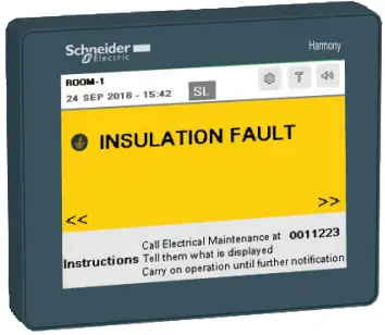
MFR40472 Vigilohm Local Remote Display
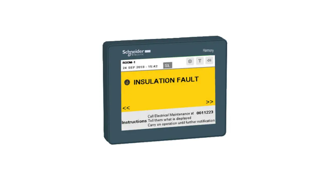
![]() Local Remote Display (Version 2.0.0) to display messages inside the operation theatre. The messages include insulation fault, transformer overload and overheat, product error, system error, circuit breaker trip, digital input fault, and communication error.
Local Remote Display (Version 2.0.0) to display messages inside the operation theatre. The messages include insulation fault, transformer overload and overheat, product error, system error, circuit breaker trip, digital input fault, and communication error.
Commercial reference IMDLRDH
www.se.com ![]() Local Remote Display
Local Remote Display
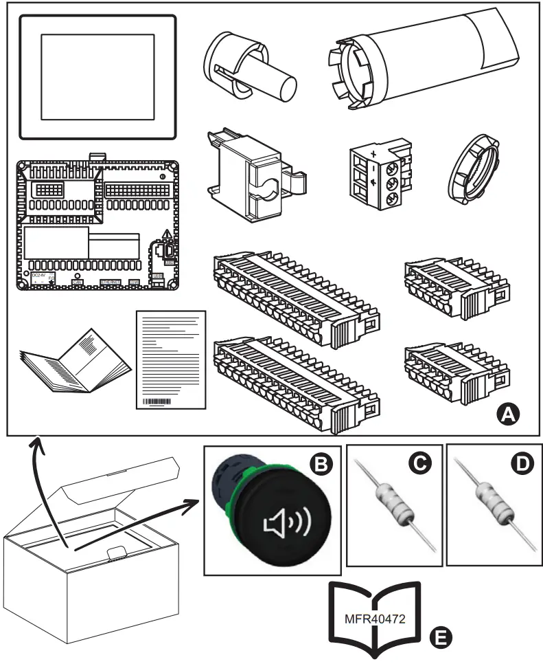
| Description | Commercial Reference/Part number/Range | |
| A | HMI Controller | HMISCU8A5 |
| B | Continuous Buzzer | XB5KSB |
| C | Resistor | 39 kΩ 2 W |
| D | Resistor | 2 MΩ 0.5 W |
| E | Instruction Sheet | MFR40472 |
Note: Do not use the product if it is damaged. Contact Schneider Electric customer care representative for support (www.se.com/support).
Safety precautions
![]() DANGER
DANGER
HAZARD OF ELECTRIC SHOCK, EXPLOSION, OR ARC FLASH
- Apply appropriate personal protective equipment (PPE) and follow safe electrical work practices. See NFPA 70E in the USA, CSA Z462 or applicable local standards.
- Turn off all power supplying this device and the equipment in which it is installed before working on the device or equipment.
- Always use a properly rated voltage sensing device to confirm that all powers are off.
- Treat I/O wiring connected to multiple devices as hazardous live until determined otherwise.
- Do not exceed the device’s ratings for maximum limits.
- Do not use this device for critical control or protection applications where human or equipment safety relies on the operation of the control circuit.
Failure to follow these instructions will result in death or serious injury.
Installation
- Install the HMI Controller.
- Connect devices as per the configurations supported. Refer Section 4 for various configurations.
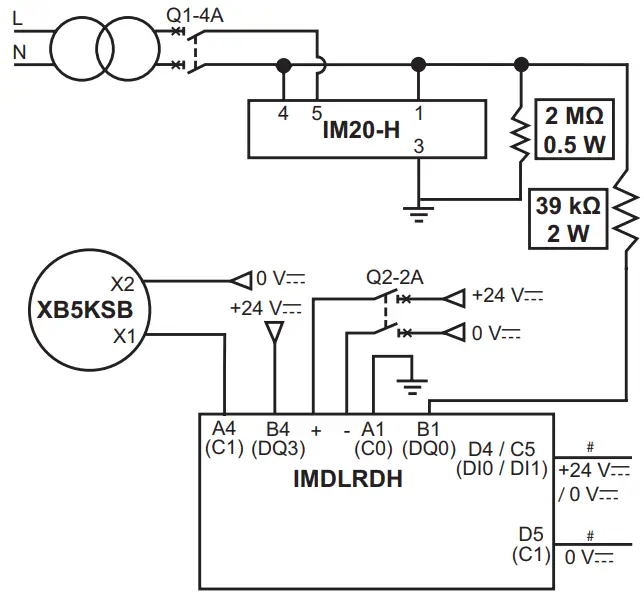
Note: Refer Harmony SCU HMI controller quick reference guide (S1B90406) for installation and wiring information. - Connect the 2 MΩ resistor between the pins 1 and 3 of the IM20-H.
- Connect the buzzer between the power supply (0 Vc) and pin A4 (C1) of the IMDLRDH.
- Connect the power supply (+24 Vc) to the pin B4 (DQ3) of the IMDLRDH.
- Connect the 39 kΩ resistor between the pin 1 of the IM20-H and the pin B1 (DQ0) of the IMDLRDH.
- Connect the pin A1 (C0) of the IMDLRDH to system ground.
Note: IMDLRDH can detect 2 digital outputs from the application. - Connect digital output from the application between the pins D4 (DI0) or C5 (DI1) and D5 (C1) of the IMDLRDH.

Configuration
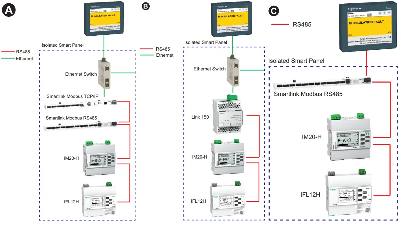
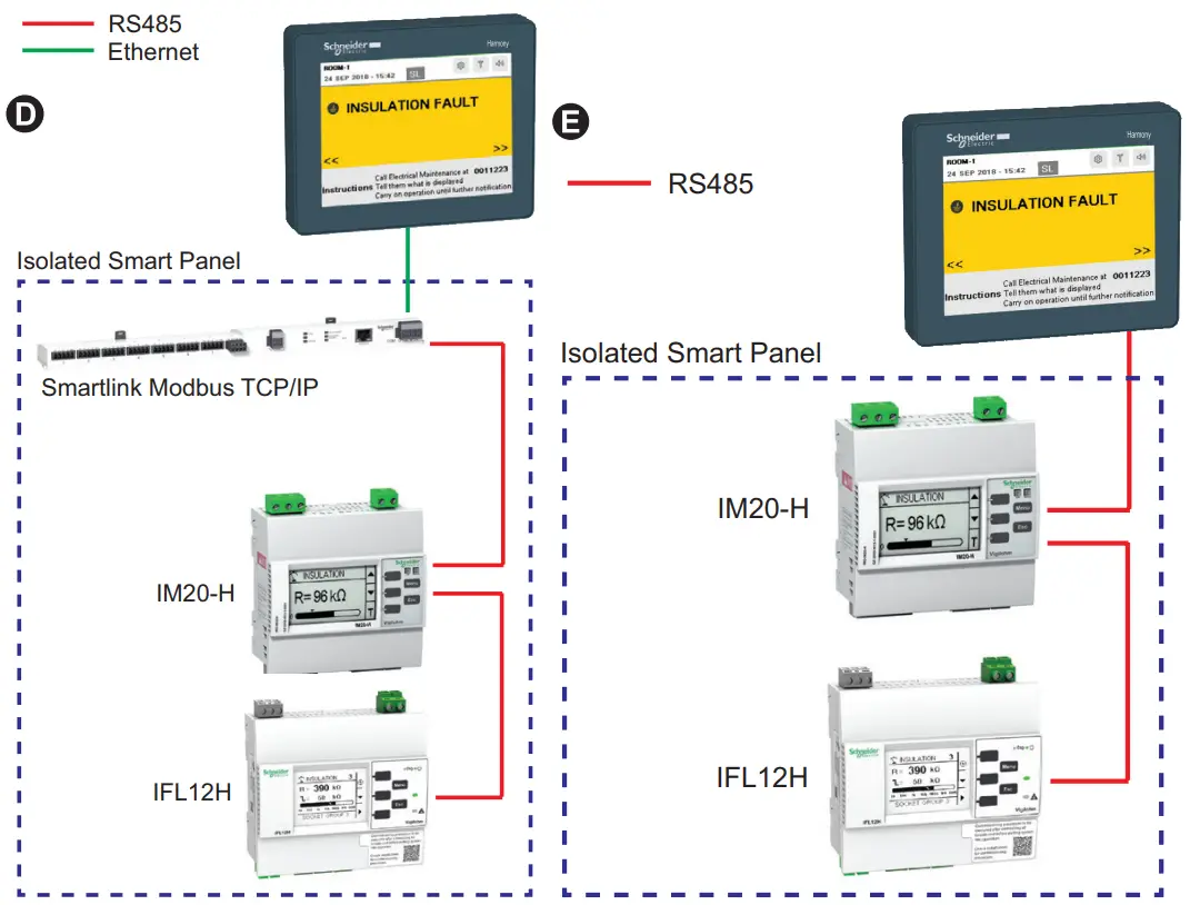
| Compatible Devices | Commercial reference |
| IM20-H+1 | IMD-IM20-H |
| IFL12H+2 | IMDIFL12H |
| Smart link | A9XMSB11 and A9XMEA08 |
| Link150 | EGX150 |
+1: Firmware Version ≥ 2.3.0
+2: Up to 4 devices
Setup
Prerequisites:
- Ensure that the installation is complete as per section 3.
- Make note of the Modbus address of the all the connected devices. This information is required for configuring the devices.
Note: To edit or enter any value, touch the editable value and a data entry keypad displays. Use this keypad to enter the desired value and touch the Enter button to validate.
Steps:
- Power ON the HMI controller.
The Password page displays.
Note: The default password is 0000. - Enter the password and touch the ok button.
The Change Password page displays. - Enter the new password and touch the ok button.
The Settings page displays.Parameter Description Default value Allowed values LANGUAGE Select the desired language English • English
• German
• Spanish
• French
• Portuguese
• ItalianROOM Enter the desired room name ROOM-1 Length: 1 to 16 characters
• Alphabets
• Numerical
• Special charactersCOMM Select the desired communication protocol RS485 • RS485
• TCP/IPNote: For TCP/IP, refer to TCP/IP configuration CABINET – 1 IMD Enter the Modbus address 0 1…247 IFL Enter the Modbus address and the desired channel name 0 (Modbus Address) For channel names:
IFL12H-1 : A1…A12
IFL12H-2 : B1…B12
IFL12H-3 : C1…C12
IFL12H-4 : D1…D12Modbus Address: 1…247
Channel names: Length: 1 to 20 characters
• Alphabets
• Numerical
• Special charactersSML Enter the Modbus address 0 SML1 : 1…247
SML2 : 255Touch and enable the configured channels. Note: SML1 refers to the A9XMSB11 and SML2 refers to A9XMEA08. Parameter Description Default value Allowed values DI Select the desired configuration for digital inputs (DI- 0, DI-1, DI-6 and DI-7) and enter the message. Digital Input Configuration:
Disable
Alarm State Configuration:
Low
Message:
For DI-0: DI-0 message
For DI-1: DI-1 message
For DI-6: DI-6 message
For DI-7: DI-7 messageDigital Input Configuration:
• Disable
• Enable Alarm State
Configuration:
• Low
• High Message: Length: 1 to 20 characters
• Alphabets
• Numerical
• Special charactersMESSAGE Configure the messages for both the panels.
Note: You can configure 3 lines of message.Call Electrical Maintenance at 00000
Tell them what is displayed Carry on operation until further notificationLength: 1 to 40 characters
• Alphabets
• Numerical
• Special charactersTouch the following parameters to view the information:
Parameter Description ABOUT Displays the product name, version, and the QR code. QR code reads the device web page. ESC Displays the Installation Ready message displays with green background. - Touch and hold at bottom right corner of the device and the HMI controller settings page displays.
- Set the date/time of the HMI controller. Refer Harmony SCU HMI controller hardware guide (EIO0000001232) for date/time configuration.
Note: To update settings after connecting different devices, touch the icon.
icon.
TCP/IP configuration:
If you chose TCP/IP communication protocol, perform the following steps:
- Enter the IP address of the gateway (Smart link or Link150).
Note: If you have configured 2 panels, enter the IP address of gateway of both the panel. - Touch the Magelisip button.
The HMI controller settings page displays. - Enter the IP address of the IMDLRDH in the network settings. Refer Harmony SCU HMI controller hardware guide (EIO0000001232) for network configuration.
Note: All IP addresses should be in the same domain.
Insulation Test
This will test the insulation monitoring system in compliance with IEC60364-7-710.
To perform insulation test, touch the icon on the top right corner.
The insulation test begins. A percentage bar is displayed with the progress.
During self test,
- An insulation fault is induced and the INSULATION FAULT message displays and buzzer turns ON.
- The induced insulation fault is recovered and the Installation Ready message displays and buzzer turns OFF.
- A success message displays.
Note: Success message displays for two panels if it is configured.
Note: If error message displays, contact Schneider Electric customer care representative for support.
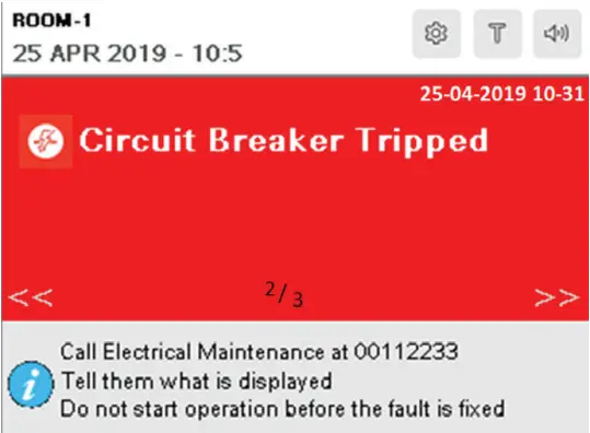
Message Screens
Following are the list of message screens supported:
Note: Follow the instructions displayed whenever you see these message screens.
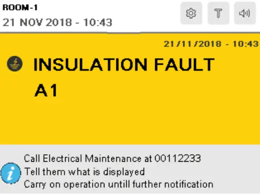
This screen continue to display until the system recovers from the insulation fault.
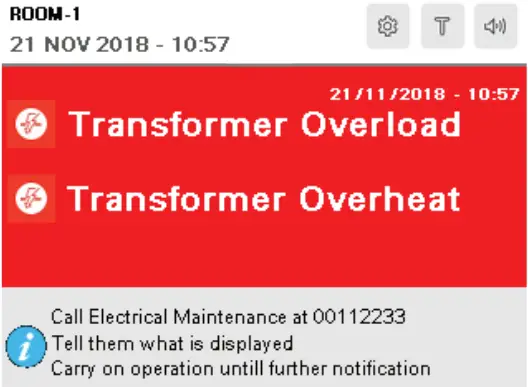
This screen continue to display until the system recovers from the transformer overload or overheat.
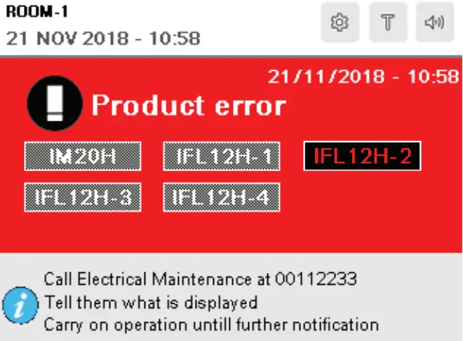
Contact Schneider Electric customer care representative for support.
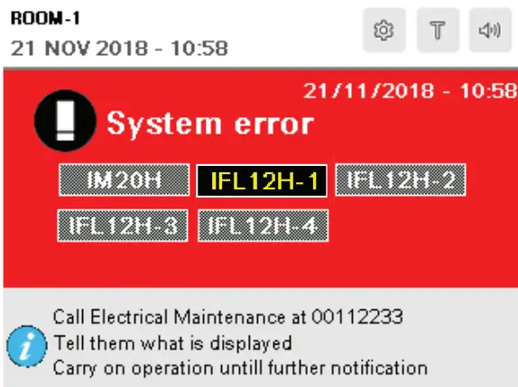
Check the underground system for any issues. This screen continue to display until the system recovers from the error.
On any message, the buzzer turns ON. Touch the ![]() icon to turn OFF the buzzer If multiple messages are displayed, touch and hold the
icon to turn OFF the buzzer If multiple messages are displayed, touch and hold the ![]() and
and ![]() icons to navigate and view all the displayed messages.
icons to navigate and view all the displayed messages.
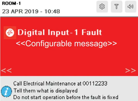
Check the connected devices for any issues. This screen continue to display until the issue is resolved.
To check the settings, touch and hold the ![]() icon for 2 seconds and release it.
icon for 2 seconds and release it.
To check the settings, touch and hold the ![]() icon for 2 seconds and release it.
icon for 2 seconds and release it.
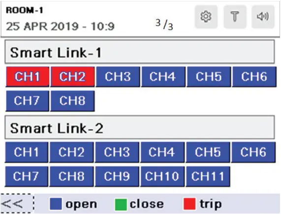
To identify the tripped channels of the connected device, touch on the Circuit Breaker Tripped message and the following screen displays:
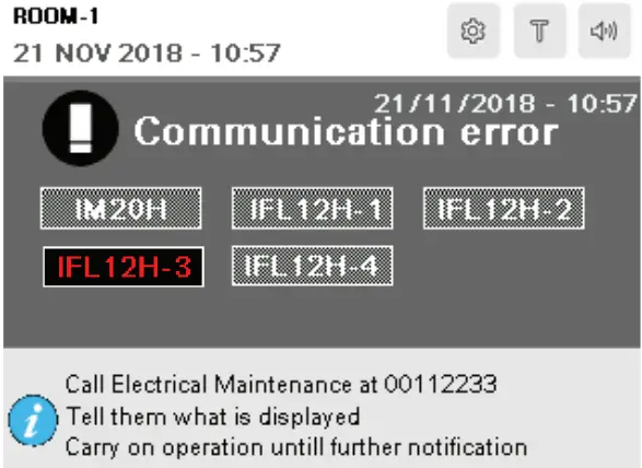
To check the communication settings of the highlighted devices, touch and hold the icon for 2 seconds and release it.![]() Note: If the existing communication error is not fixed in 1 minute, this message displays again.
Note: If the existing communication error is not fixed in 1 minute, this message displays again.
Specifications
Refer the following device documentation for specifications:
| Device | Commercial Reference | Title | Part Number |
| HMI Controller | HMISCU8A5 | Harmony SCU HMI controller quick reference guide | S1B90406 |
| Harmony SCU HMI controller hardware guide | EIO0000001232 | ||
| IFL12H | IMDIFL12H | Vigilohm IFL12H instruction sheet | QGH34270 |
| Vigilohm IFL12H user manual | 7EN02–0407 | ||
| IM20H | IMD-IM20-H | Vigilohm IM20-H instruction sheet | S1A40442 |
| Vigilohm IM20-H user manual | VIGED310023EN | ||
| Smartlink | A9XMSB11 | Smartlink instruction sheet | S1B33423 |
| A9XMEA08 | Smartlink instruction sheet | NVE12086 | |
| A9XMSB11/A9XMEA08 | Smartlink user manual | DOCA0073EN | |
| Link150 | EGX150 | Ethernet Gateway Link150 Instruction sheet | NHA50221 |
Notices
Read these instructions carefully and look at the equipment to become familiar with the device before trying to install, operate, service or maintain it.
Electrical equipment should be installed, operated, serviced and maintained only by qualified personnel. No responsibility is assumed by Schneider Electric for any consequences arising out of the use of this material. A qualified person is one who has skills and knowledge related to the construction, installation, and operation of electrical equipment and has received safety training to recognize and avoid the hazards involved.
Schneider Electric is trademark or registered trademark of Schneider Electric in France, the USA and other countries.
- This product must be installed, connected and used in compliance with prevailing standards and/or installation regulations.
- If this product is used in a manner not specified by the manufacturer, the protection provided by the product may be impaired.
- The safety of any system incorporating this product is the responsibility of the assembler/installer of the system.
As standards, specifications and designs change from time to time, always ask for confirmation of the information given in this publication.

![]() Schneider Electric
Schneider Electric
35 rue Joseph Monier
92500 Rueil Malmaison,France
Phone: +33 (0) 1 41 29 70 00
www.se.com
Schneider Electric Limited![]() Stafford Park 5
Stafford Park 5
Telford TF3 3BL
United Kingdom
MFR40472-03
© 2022 Schneider Electric. All rights reserved.
04/2022


