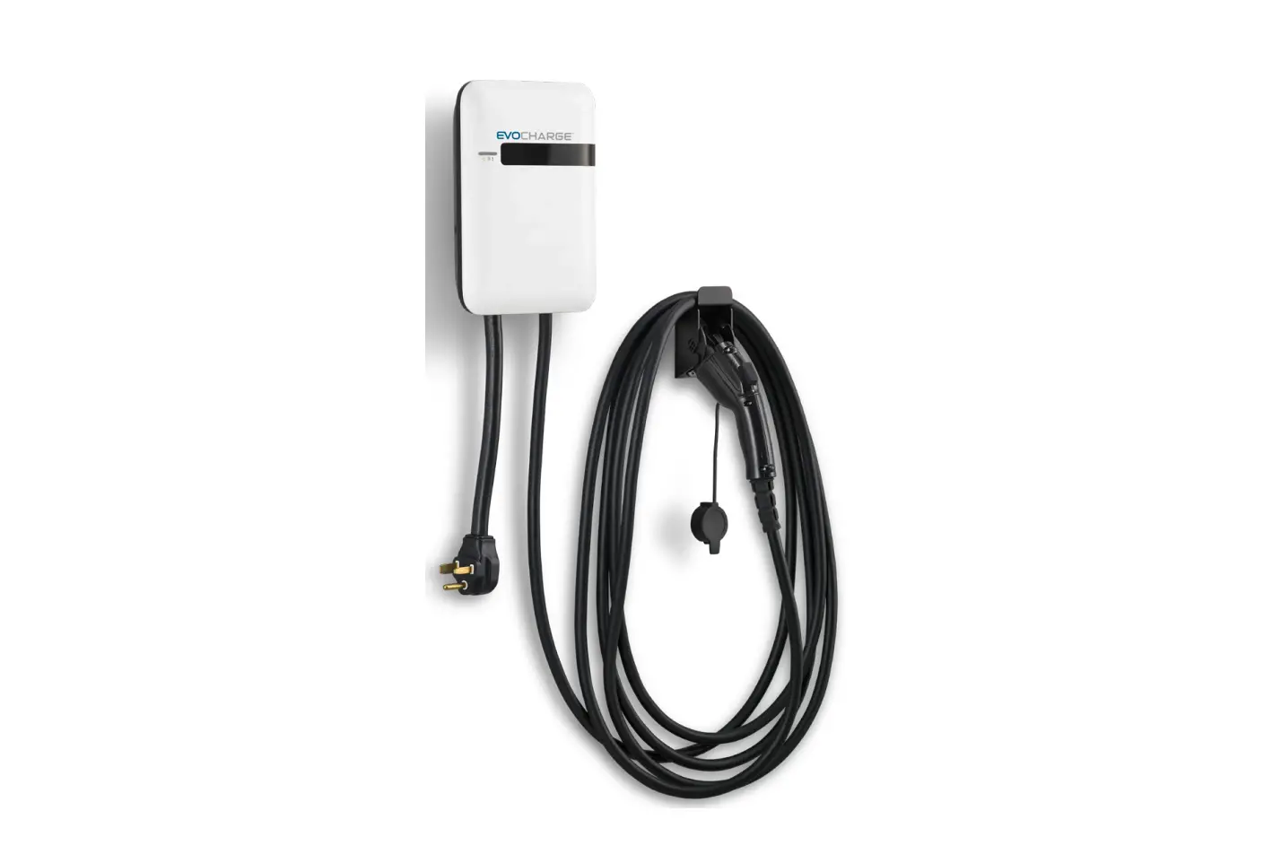
EVOCHARGE iEVSE 40a Evse Charging Station Installation Guide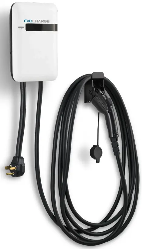
Safety Check
- Check for transport damages.
- Before connecting the product to the power supply, check that the power supply voltage and current rating corresponds with the power supply details shown on the product rating label.
- The charge point must be installed only by a licensed electrician in accordance with the provisions of the local electrical industry construction and should comply with national electrical codes and standards.
- Before installing the charge point, make sure you have read all of these instructions in this manual and fully understand its contents. Appropriate protection is required when connecting to a main switchboard. The tools and parts used as outlined in the section “Tools & parts required for installation”.
![]() Disconnect the power supply before installing or repairing the charge point. Failure to do so may result in physical injury or damage to the power supply system and the charge point.
Disconnect the power supply before installing or repairing the charge point. Failure to do so may result in physical injury or damage to the power supply system and the charge point.
![]() Avoid touching or pressing the OLED screen all times, as this may result in damage to the OLED screen.
Avoid touching or pressing the OLED screen all times, as this may result in damage to the OLED screen.
![]() RISK OF SUFFOCATION: Keep any packing materials away from children – these materials are a potential source of danger, e.g. suffocation.
RISK OF SUFFOCATION: Keep any packing materials away from children – these materials are a potential source of danger, e.g. suffocation.
Grounding instructions
The charge point must be installed with an equipment grounding conductor. Use a dedicated grounding wire with a ring terminal to connect to the grounding terminal block.
Tools & parts required for installation
| Tool | Qty | Size | Supplier | Remark |
| Mounting Bracket | 1 | 194x09x9 mm | Model Accessories | Fasten charge point to the wal |
| Holster ASSY | 1 | 58x58x70 mm | Model Accessories | Hold EV charging plug |
| Screw | 4 | Tapping: #12Mechanical: M6 | Model AccessoriesCommercially Available | Fasten mounting bracket and hook |
| Wire, Copper | 3 | 8 AWG | Commercially Available | UL1015 (recommended) |
| Heat Shrink Tube | 3 | For 8 AWG wire | Commercially Available | Protect wires and terminals |
| Terminal | 3 | For 8 AWG wire | Commercially Available | Connect input wires to the terminal block |
| Conduit | 1 | 1 inch | Commercially Available | Protect power cable |
| Torx Screwdriver | 1 | T20 | Commercially Available | |
| Philips Screwdriver | 1 | PH3 | Commercially Available | |
| Hexagon Socke | 1 | 5/16 | Commercially Available | Tighten #12 tapping screws |
| Torque Wrench | 1 | 35 kgf-cm min | Commercially Available |
Install the charge point
![]() Disconnect power at the circuit breaker before installation.
Disconnect power at the circuit breaker before installation.
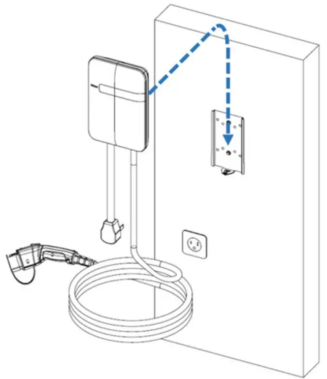
![]() Before mounting, determine the suitable mounting location. The unit must be fixed to a wooden or masonry/concrete wall using hardware that is appropriate for the surface. Do not install on drywall, wall boards or thin plywood. The fixing point must be capable of supporting the weight of the unit.
Before mounting, determine the suitable mounting location. The unit must be fixed to a wooden or masonry/concrete wall using hardware that is appropriate for the surface. Do not install on drywall, wall boards or thin plywood. The fixing point must be capable of supporting the weight of the unit.
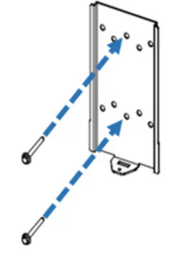
Secure the mounting bracket to the wall with appropriate screws.
Follow applicable accessibility requirements for the mounting position. The unit shall be stored or located at a sufficient height. Follow local electric code and applicable standards.
For indoor use: The unit should be mounted between 18 inches (450 mm) and 4 feet (1.2m) from the floor. Follow local electric code and applicable standards.
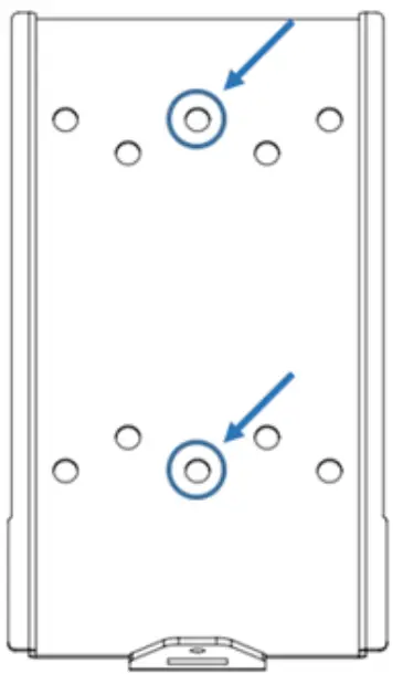
For outdoor use: The unit should be mounted between 24 inches (600 mm) and 4 feet (1.2m) from the floor. Follow local electric code and applicable standards. The mounting bracket has ten screw holes. If only two screws are to be used to fasten the mounting bracket, use the middle two screw holes of the mounting bracket. The other screw holes are reserved for the user.
Screw suggestion:
- For masonry walls, use M6 mechanical screws. (Commercially available)
- For finished walls supported by wood studs, locate the stud and use 1/4” or M6 tapping screws. (Commercially available)
- Please use following torque force:
| Screw | Torque | |
| M6 | 25 kgf.cm min | 21.7 lb-in min |
| #12 | 25 kgf.cm min | 21.7 ln-in min |
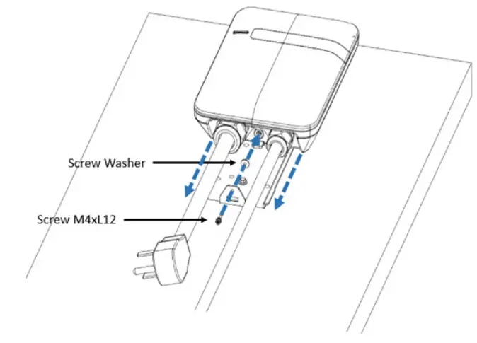
Mount the charge point onto mounting bracket and lock the screw.
- Put the charge point on the mounting bracket.
- Fix charge point on mounting bracket with M4 screw and screw washer.
- Please refer to the following torque:
| Screw | Torque | |
| M4 | 16 kgf.cm | 13.88 lb-in |
- Installing the mounting bracket

- Screw holes of mounting bracket

- Charge point and mounting bracket

- Screw locking position

Plug in the power cord (BC3/SC3 ONLY)
The outlet should be located at 20-26 inches from the ground. Refer to the installation template to decide where to install the charge point.
Plug in the power cord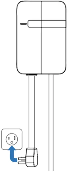
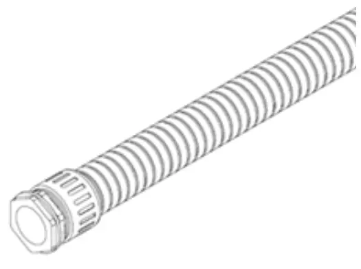
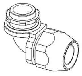
Choose the appropriate conduit in accordance with all applicable state, local and national electrical codes and standards.
- Conduit

- Right angle conduit

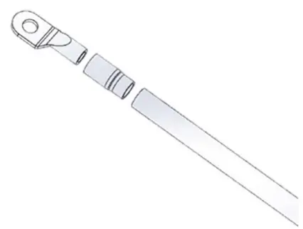
Clamp the copper sleeve terminal to connect the copper wire.
Refer to the following wire specification. Use a hand tool to cut the outer layer of the wire and leave around 12mm of length for connecting the copper sleeve terminal
| Terminal | Conductor | Rating |
| L1, L2 | 6 AWG | 90C copper wire |
| G | 10 AWG | 90C copper wire |
Note
- Please make sure there is no copper wire out of ferrule.
- The dimensions of ferrule terminal after cramping is 4.8mm square MAX.
Connect copper sleeve terminal to wire
Electrical wiring to the charge point
- Disassemble top cover.
- Use Philips screwdriver to release terminal screws.
- Fold the wire end to pass through the conduit and insert into the input hole.
- ix the copper wire on the corresponding terminal block. The wiring instruction is printed in front of the terminal block (L1/ L2/G).
- Use the following torque to connect the wire terminal to the terminal block
| Torque | |
| 1.2 N-m | 10.5 ln-in |
The recommended terminal specifications are as follows:
Dimensions of terminal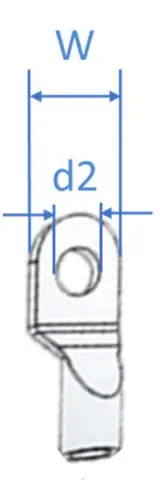
| Terminal | Dimension (mm) |
| W | ≤ 9.5 |
| d2 | 4-6.4 |
Input wiring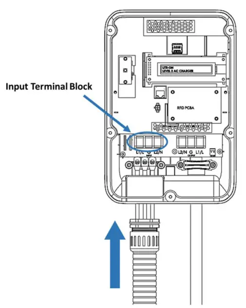
![]() CAUTION: To reduce the risk of fire, connect only to a circuit provided with 40 amperes maximum branch circuit overcurrent protection in accordance with the National Electrical Code, ANSI/ NFPA 70, and the Canadian Electrical Code, Part I, C22.1.
CAUTION: To reduce the risk of fire, connect only to a circuit provided with 40 amperes maximum branch circuit overcurrent protection in accordance with the National Electrical Code, ANSI/ NFPA 70, and the Canadian Electrical Code, Part I, C22.1.
![]() CAUTION: If this unit is installed outdoors, the outlet must be rated for outdoor installation. The outlet must be installed properly to maintain the proper NEMA rating of the enclosure
CAUTION: If this unit is installed outdoors, the outlet must be rated for outdoor installation. The outlet must be installed properly to maintain the proper NEMA rating of the enclosure
| Model | Current rating |
| Intelligent Charger-40A | 40A |
Lock the conduit on the enclosure. Please refer to the following torque:
| Torque | Torque | |
| 1 “ | 35 kgf.com | 30.36 lb-in |
Reassemble the top cover. Please refer to the following torque:
| Screw | Torque | |
| M4 | 16 kgf.com | 13.88 lb-in |

For additional products, field support and cable management solutions visit evocharge.com or contact us at 888-653-0160.
888-653-0160
[email protected]
evocharge.com


 Charge Installation Guide")