![]() YRH(V)*KTE/KTG Copeland Scroll Horizontal
YRH(V)*KTE/KTG Copeland Scroll Horizontal
Compressors for Transport Applications
Installation Guide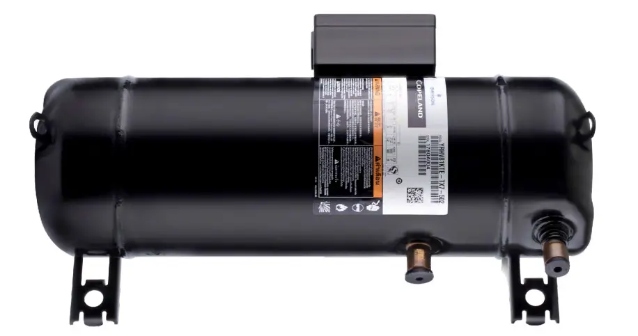
About these guidelines
The purpose of these guidelines is to provide guidance in the application of Copeland™ scroll compressors in users’ systems. They are intended to answer the questions raised while designing, assembling and operating a system with these products.
Besides the support they provide, the instructions listed herein are also critical for the proper and safe functioning of the compressors. The performance and reliability of the product may be impacted if it is not used according to these guidelines or is misused.
These application guidelines cover mainly transport applications. In transport, special considerations such as high vibration and shocks, power supply characteristics, high ambient temperatures, frequent cycling and other factors may apply. It is the responsibility of the system designer/planner to define the individual requirements to qualify the compressor and the complete system for their specific needs. Please contact the Application Engineering department at Emerson for additional support.
Safety instructions
Copeland scroll compressors are manufactured according to the latest relevant European, UK andUS safety standards. Particular emphasis has been placed on the user’s safety.
YRH(V)* compressors are intended for installation in systems in accordance with the followingdirectives and regulations:
| Machinery Directive MD 2006/42/EC | Supply of Machinery (Safety) Regulation 2016 |
| Pressure Equipment Directive PED 2014/68/EU | Pressure Equipment (Safety) Regulation 2008 |
| Low Voltage Directive LVD 2014/35/EU | Electrical Equipment (Safety) Regulation 2016 |
They may be put to service only if they have been installed in systems according to instructions and conform to the corresponding provisions of the applicable legislation.
NOTE: Only dedicated compressors are allowed to be used with flammable refrigerants.
Emerson marks all compressors that are qualified for flammable refrigerants with a sticker indicating the usage of such refrigerants. Systems using flammable refrigerants must be executed correctly while observing safety rules, as specified in corresponding safety standards such as, but not limited to EN 378. They must comply with any and all applicable legislation and regulations. Ensuring compliance remains the user’s responsibility.
The Material Safety Datasheet (MSDS) for each individual refrigerant shall be considered when working with these types of refrigerant – please check this document provided by the gas supplier.
These instructions shall be retained throughout the lifetime of the compressor.
You are strongly advised to follow these safety instructions.
1.1 Icon explanation
| WARNING This icon indicates instructions to avoid personal injury and material damage. | |
| High voltage This icon indicates operations with a danger of electric shock. | |
| Danger of burning or frostbite This icon indicates operations with a danger of burning or frostbite. | |
| Explosion hazard This icon indicates operations with a danger of explosion. | |
| Danger of explosive atmosphere This icon indicates a risk of explosiveatmosphere. | |
| Fire hazard This icon indicates a risk of flammable atmosphere. | |
| CAUTION This icon indicates instructions to avoid property damage and possible personal injury. | |
| IMPORTANT This icon indicates instructions to avoid malfunction of the compressor. | |
| NOTE | NOTE This word indicates a recommendation for easier operation. |
1.2 Safety statements
- Refrigerant compressors must be employed only for their intended use. The system has to be labelled according to the applicable standards and legislation.
- Only qualified and authorized RACHP (refrigeration, air conditioning and heat pump personnel) are permitted to install, commission and maintain this equipment. Only competent personnel (as specified in EN 13313) qualified for flammable refrigerant handling are permitted to commission, initiate and maintain the compressor/refrigeration systems; non-trained personnel, including the user, are not allowed to do so and must call on an expert.
- The maximum refrigerant charge is specified in standards such as, but not limited to EN 378. The system designer shall implement all safety measures defined by the applicable standards and the maximum refrigerant charge shall not be exceeded.
- If a flammable atmosphere is detected, immediately take all necessary precautions to mitigate the risk as determined in the risk assessment.
- Electrical connections must be made by qualified electrical personnel.
- All valid standards for connecting electrical and refrigeration equipment must be observed.
- The national legislation and regulations regarding personnel protection must be observed.
![]() Use personal safety equipment. Safety goggles, gloves, protective clothing, safety boots and hard hats should be worn where necessary.
Use personal safety equipment. Safety goggles, gloves, protective clothing, safety boots and hard hats should be worn where necessary.
1.3 General instructions
![]() WARNING
WARNING
Pressurized system! Serious personal injuries and/or system breakdown! Accidental system start before complete set-up must be avoided.
Never leave the system unattended without locking it out electrically when it is on vacuum and has no refrigerant charge, when it has a holding charge of nitrogen, or when the compressor service valves are closed.![]() WARNING
WARNING
System breakdown! Personal injuries! Only approved refrigerants and refrigeration oils must be used.![]() WARNING
WARNING
High shell temperature! Burning! Do not touch the compressor until it has cooled down. Ensure that other materials in the area of the compressor do not come into contact with it. Lock and mark accessible sections.![]() CAUTION
CAUTION
Overheating! Bearing damage! Do not operate compressor without refrigerant charge or without it being connected to the system.![]() CAUTION
CAUTION
Contact with refrigerant oil! Material damage! Polyolester (POE) and polyalkylene glycol (PAG) lubricants must be handled carefully and the proper protective equipment (gloves, eye protection, etc.) must be used at all times.
Refrigerant oil must not come into contact with any surface or material that it might damage, including but without limitation, certain polymers, eg, PVC/CPVC and polycarbonate.![]() IMPORTANT
IMPORTANT
Transport damage! Compressor malfunction! Use original packaging.
Avoid collisions and tilting.
Product description
2.1 Compressor range
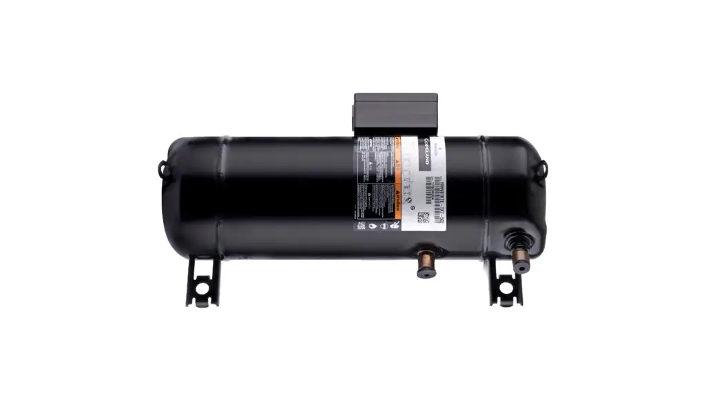
These application guidelines cover Copeland™ scroll horizontal compressor models YRH(V)*KTE/KTG (fixed- and variable-speed models). The Copeland scroll horizontal compressor utilizes the same fundamental technology as the vertical models but incorporates a specific lubrication system to enable horizontal operation. The variable-speed scroll compressors allow precise matching of capacity over a much wider range than the fixed-speed models.
| Compressor | Cooling capacity (kW) | Motor range (Hz) | Frequency | |
| R454C | R290 | |||
| YRH72KTE | 13. | TFD | 50 Hz | |
| YRH72KTG | 13. | TFD | 50 Hz | |
| YRHV72KTE | 14. | TX7 | 25-100 Hz | |
| YRHV72KTG | 13. | TX7 | 25-100 Hz | |
| YRH81KTE | 15. | TFD | 50 Hz | |
| YRH81KTG | 15. | TFD | 50 Hz | |
| YRHV81KTE | 15. | TX7 | 25-100 Hz | |
| YRHV81KTG | 15. | TX7 | 25-100 Hz | |
Refrigerant dew point temperature, evaporating temperature: 5 °C; condensing temperature: 50 °C; suction gas superheat: 10 K; liquid sub-cooling: 0 K; frequency: 50 Hz
Table 1: YRH(V)* model overview
2.2 Special requirements for transport applications
Transport applications for air conditioning, refrigeration or heat pump can be particularly sensitive and require experience and thorough case-by-case analysis. Compared to stationary systems, transport applications can have significantly higher requirements with regard to mechanical load, system design, general function, tightness, conditions of the electrical supply and many other details.
The qualification for the whole system and all individual requirements, eg, component selection, piping, piping layout, fixation, as well as a study about shock, vibration and load requirements must be carried out by the system designer. Emerson can provide support and assistance with individual projects.
Emerson requirements and recommendations for transport applications are as follows:
- During the risk assessment process and when dealing with R454C and R290, special attention must be paid to flammability.
- Careful selection of mounting parts based on noise and vibration test results.
- Addition of external low leak check valves in the discharge line of the compressor for all models.
- Refrigerant charging into the liquid line and after the external check valve to avoid damage.
- Mandatory external discharge temperature protection for all compressors.
- Installation of a solenoid valve in the liquid line to the evaporator for pump-out, pumpdown or high-to-low-side isolation purposes.
- Installation of low- and high-pressure controls, preferably direct acting.
- Carefully set inverter current limit for TX* motor versions, because there is no internal motor protection.
- Addition of external phase sequence control to avoid reverse rotation and lubrication issues.
- Installation of hot gas bypass not recommended.
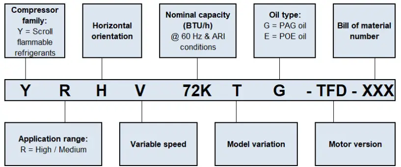
2.3 Nomenclature
The model designation contains the following technical information about the compressor:
2.4 BOM variations
The BOM (bill of material) marking at the end of the compressor designation indicates the different compressor layouts and details. YRH(V)*KTE/KTG compressor models are available in the following BOM version:
| BOM | Suction and discharge connections | T-Box | Mounting parts | Features |
| NBF | Brazing stub tubes | 1P56 | Without | Single compressor |
Table 2: BOM designation
Please refer to the Emerson price list for more details.
2.5 Application range
2.5.1 Qualified refrigerants and oils![]() IMPORTANT
IMPORTANT
Always consider the temperature glide of refrigerant blends. Some refrigerant blends (for example R454C) have a significant temperature glide. This requires special attention for the design of condenser/evaporators and when adjusting pressure and superheat controls.![]() IMPORTANT
IMPORTANT
R454C is a refrigerant blend with low GWP. It contains HFO, which has a low chemical stability in the presence of air or humidity. The same levels of cleanliness, dryness and evacuation in the refrigerant circuit are required as in HFC & POE applications, including the use of filter dryers.![]() IMPORTANT
IMPORTANT
Both PAG polyalkylene glycol and POE polyolester oils are hygroscopic.
Moisture absorption during filling, installation or any other work on the open refrigerant system should be minimised using appropriate precautions and working practices.
In comparison with POE, PAG oil is even more hygroscopic. However, in systems with PAG oil, the same measures to prevent moisture ingress and removal, eg, minimizing the contact with air, using appropriate vacuuming methods, using a filter dryer, etc, can be used as in systems with POE oil.
NOTE: R454C is classified as A2L (mildly flammable) refrigerant, while R290 is classified as A3 (flammable) refrigerant.
Oil recharge values can be taken from the compressor nameplate or from Copeland Select software available at www.climate.emerson.com/en-gb.
2.5.2 Application limits
CAUTION![]() Inadequate lubrication! Compressor breakdown! The superheat at the compressor suction inlet must always be sufficient to ensure that no refrigerant droplets enter the compressor. For a typical evaporator-expansion valve configuration a minimum stable superheat of at least 10 K is required.
Inadequate lubrication! Compressor breakdown! The superheat at the compressor suction inlet must always be sufficient to ensure that no refrigerant droplets enter the compressor. For a typical evaporator-expansion valve configuration a minimum stable superheat of at least 10 K is required.
For application envelopes and technical data, please refer to Copeland Select software available at www.climate.emerson.com/en-gb.
2.5.3 PED category and maximum allowable pressure PS
The pressure PS is the maximum allowable pressure at the low- and high-pressure sides of the compressor. The maximum pressure value PS for the individual compressor type is printed on the nameplate of the compressor. Safety is established in compliance with the relevant standards applicable to the given product.
The PED category is assigned according to the Pressure Equipment Directive PED 2014/68/EU.
Requirements apply to the relevant pressure levels in the compressor when the product of “pressure relative to the environment” by “related internal free volume” (P x V) exceeds given limits. When calculating the PED category, the high- and low-pressure sides have to be calculated separately.
The highest of the calculation results is considered.
Additionally, a distinction must be made between refrigerants of fluid group 1 (flammable) and fluid group 2 (non-flammable). YRH(V)*KTE compressors can be operated with R454C (A2L refrigerant) and YRH(V)*KTG compressors can be operated with R290 (A3 refrigerant). Both refrigerants belong to fluid group 1.
YRH(V)*KTE/KTG horizontal scroll compressors are PED class II.
| Compressor | PS Low-pressure side | PS High-pressure side | TS max. Low-pressure side | Fluid group | PED class |
| YRH(V)72KTE & YRH(V)81 KTE | 20 bar(g) | 32 bar(g) | 50 C | 1 | H |
| YRH(V)72KTG & YRH(V)81 KTG | 20 bar(g) | 32 bar(g) | 50 °C | 1 | II |
Table 4: Maximum allowable pressures and PED category
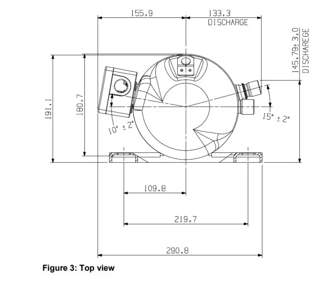
2.6 Dimensions of YRH(V)*KTE/KTG compressors 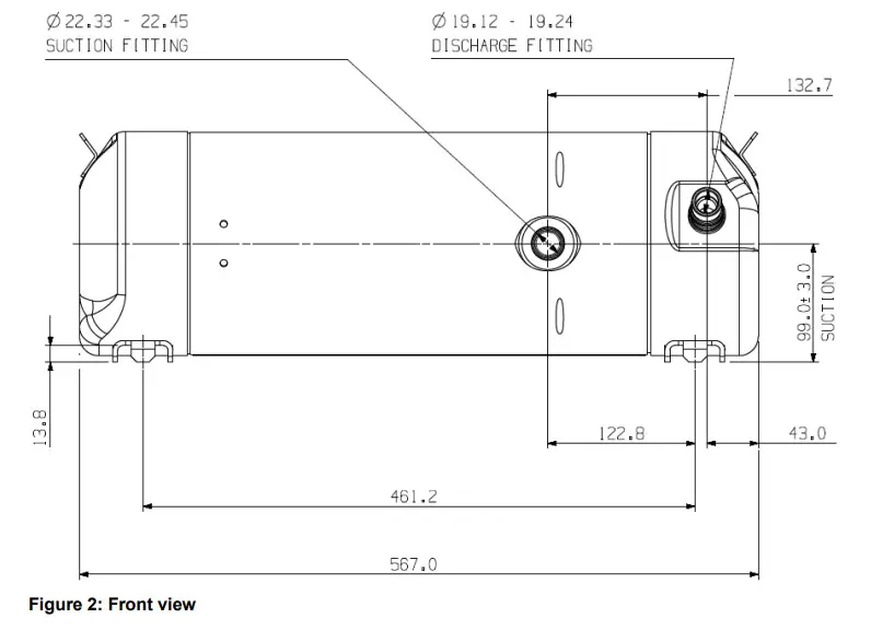
Installation
![]() WARNING
WARNING
High pressure! Injury to skin and eyes possible! Be careful when openingconnections on a pressurized item.
3.1 Compressor handling
3.1.1 Transport and storage
WARNING
Risk of collapse! Personal injuries! Move compressors only with appropriate handling equipment according to weight. Respect stacking loads according to Figure 4. Check the tilting stability and if needed take action to ensure the stability of the stacked loads. Keep the packaging dry at all times.
![]() Respect the maximum number of identical packages which may be stacked on one another, where “n” is the limiting number:
Respect the maximum number of identical packages which may be stacked on one another, where “n” is the limiting number:
▪ Transport: n = 2
▪ Storage: n = 4
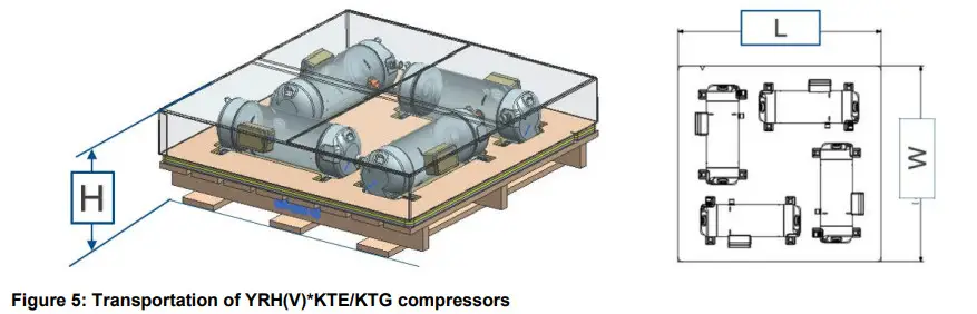
| Compressor model | L (mm) | W (mm) | H (mm) | Gross weight (kg) | Net weight (kg) |
| YRH(V)*KTE YRH(V)*KTG | 1175 | 1130 | 345 | 230 | 196 |
Table 5: Packaging dimensions for YRH(V)*KTE/KTG compressors transportation
3.1.2 Positioning and securing![]() IMPORTANT
IMPORTANT
Handling damage! Compressor malfunction! Only use the lifting eyes whenever the compressor requires positioning. Do not use the discharge or suction connections for lifting to avoid damage or leaks.
The lifting tabs are designed for the transportation of the compressor alone.
Do not use the lifting tabs for the transportation of the complete unit.
NOTE: Two lifting tabs are located on the side of the compressor shell end caps. It is essential to use these lifting devices to maintain the compressor in the horizontal position during handling, installation or removal in order to avoid damage to the compressor.
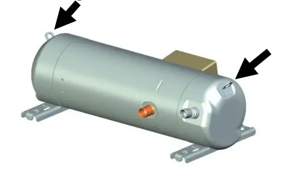
Figure 6: Handling of a horizontal scroll compressor
AGL_AC_ST_YRH_EN_Rev01
Horizontal scroll compressors have a holding charge and are factory-filled with dry air. It is recommended to remove the discharge connection plug first before pulling the suction connection plug to allow the dry air pressure inside the compressor to escape.
Care must be taken when removing the plugs from the discharge and suction connections, because oil mist might come out and coat the tube, making the brazing process on the copper-coated tubes difficult. The copper-coated steel suction tube should be cleaned before brazing.
The plugs must be removed as late as possible before brazing so that the air humidity does not affect the oil characteristics.
No object, eg, a swaging tool should be inserted into the suction tube as it might damage the internal parts of the compressor.
3.1.3 Installation location, maximum tilting and rotating angles
Scroll compressors are capable of operating correctly with compressor ambient humidity between 30 and 95 %. For correct operation the compressor ambient air temperatures must be from -35 to 60 °C. The maximum allowable pressure (PS) and temperature (TS) must be respected at all times during operation and at standstill.
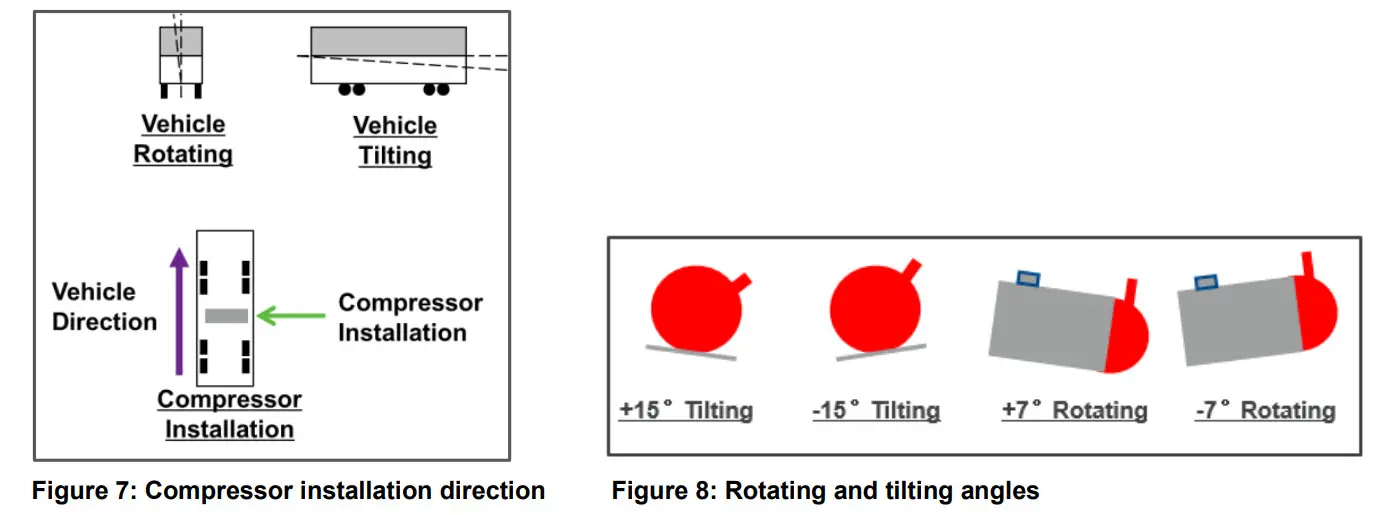
Ensure the compressors are installed on a solid level base. For the installation of horizontal scroll compressors, the recommended direction is perpendicular to the vehicle direction – see Figure 7.
The maximum gradient is 7° for rotating angles and 15° for tilting angles – see Figure 8.
3.2 Mounting parts
YRH(V)*KTE/KTG horizontal scroll compressors can be mounted solidly on the chassis using steel spacers. Alternatively, rubber mounting parts of variable hardness can be used. The unit designer should make a choice after observing the shock/vibration test results.
For the individual system review and qualification, Emerson can offer some mounting parts kit options.
3.3 Brazing procedure
![]() WARNING
WARNING
Air/flammable refrigerant mixture! Creation of a potentially flammable atmosphere! Fire hazard! Remove all refrigerant before opening the system.
When working on a refrigerant-filled system, follow the safety and working instructions given in Chapter 6 “Maintenance & repair”.![]() WARNING
WARNING
High temperature! Burning! Proceed with caution when brazing system components. Do not touch the compressor until it has cooled down. Ensure that other components in the area of the compressor do not come into contact with it.![]() CAUTION
CAUTION
Contamination or moisture! Bearing failure! Do not remove the connection plugs until the compressor is set into the unit. This minimises any entry of contaminants and moisture.![]() CAUTION
CAUTION
Blockage! Compressor breakdown! Maintain a flow of oxygen-free nitrogen through the system at very low-pressure during brazing. Nitrogen displaces the air and prevents the formation of copper oxides in the system. If allowed to form, the copper oxide material can later be swept through the system and block screens such as those protecting capillary tubes, thermal expansion valves, and accumulator oil return orifices.
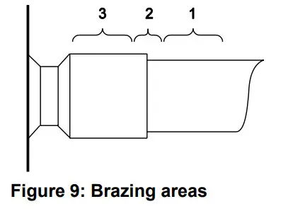
Copeland scroll compressors have copper-plated steel suction and discharge stub tubes. These stub tubes are far more robust and less prone to leaks than copper tubes. Brazing must be carried out in an appropriate manner, taking into account the different thermal properties of steel and copper.
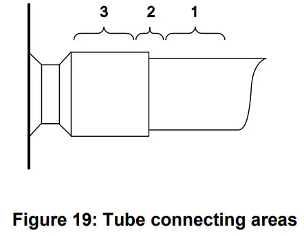
Refer to Figure 9 and procedure below for the brazing of the stub tube connections of a scroll compressor.
- Flushing oxygen-free nitrogen through the piping during the brazing process is mandatory for applications with flammable A2L and A3 refrigerants.
- The copper-coated steel tubes on scroll compressors can be brazed in approximately the same manner as any copper tube.
- Recommended brazing materials: any Silfos material is recommended, preferably with a minimum of 5 % silver. However, 0 % silver is acceptable.
- Be sure tube fitting inner diameter and tube outer diameter are clean prior to assembly.
- Using a double-tipped torch, apply heat in area 1.
- As the tube approaches brazing temperature, move the torch flame to area 2.
- Heat area 2 until braze temperature is attained, moving the torch up and down and rotating around the tube as necessary to heat the tube evenly. Add braze material to the joint while moving the torch around the joint to flow braze material around the circumference.
- After the braze material flows around the joint, move the torch to heat area 3. This will draw the braze material down into the joint. The time spent heating area 3 should be minimal.
- As with any brazed joint, overheating may be detrimental to the final result.
NOTE: Since the discharge stub contains a check valve, care must be taken not to overheat it to prevent brazing material from flowing into it.
3.4 Pressure safety controls
Emerson requires the installation of low- and high-pressure controls, preferably direct acting, for all transport systems.
3.4.1 High-pressure protection
Applicable regulations and standards, for example EN 378-2, shall be followed to apply appropriate control and ensure that the pressure never exceeds the maximum limit.
High-pressure protection is required to stop the compressor operating outside the allowable pressure limits. The high-pressure control must be installed correctly, which means that no service valve is allowed between the compressor and the pressure protection.
The high-pressure cut-out setting shall be determined according to the applicable standard, the type of system, the refrigerant and the maximum allowable pressure PS.
3.4.2 Low-pressure protection![]() CAUTION
CAUTION
Operation outside the application envelope! Compressor breakdown! A low-pressure protection shall be fitted in the suction line to stop the compressor when it operates outside the envelope limits. Do not bridge or bypass the low-pressure limiter.
Applicable regulations and standards shall be followed to apply appropriate control and ensure that the pressure is always above the required minimum limit.
Low-pressure protection is required to stop the compressor operating outside the allowable envelope limits. The low-pressure control must be installed correctly into the suction line, which means that no service valve is allowed between the compressor and the pressure protection.
The minimum cut-out setting shall be determined according to the refrigerant and the allowed operation envelope – see Select software at www.climate.emerson.com/en-gb.
3.5 System protection for operation below atmospheric pressure
WARNING
Operation below atmospheric pressure! Fire hazard! During operation below atmospheric pressure, a flammable mixture can form inside the system.
Ensure system tightness to prevent any ingress of air.
YRH(V)*KTE compressors used in R454C systems could be operated below atmospheric pressure.
In that case special requirements for safety and tightness apply.
YRH(V)*KTG compressors used in R290 systems may be operated below atmospheric pressure only when installed in hermetically sealed systems. For non-hermetic systems, the pressure must always be above atmospheric pressure. The operating pressure must be limited as defined by the operation envelope – refer to the technical documentation.
When systems using YRH(V)*KTE/KTG compressors operate below atmospheric pressure, the following precautions must be observed:
- Check all the critical points on the system and piping connections; tightness has to be ensured also at very low pressure.
- Minimum absolute working pressure: 0.5 bar.
- The installation of mechanical high-pressure and low-pressure cut-outs is mandatory. For systems provided with a service shut-off valve on the discharge side of the compressor, only a mechanical pressure cut-out shall be used. Electronic pressure limiters, which could cause delayed sensor response, are not allowed.
- The high- and low-pressure cut-outs must be installed correctly on the discharge and suction lines, which means that no service valve is allowed between the compressor and the pressure protection (refer to EN 378 or ISO 5149).
- A discharge temperature control is mandatory to stop the compressor when the maximum discharge temperature is exceeded – see section 3.7 “Discharge gas emperature protection”.
- Additional warning notices shall be affixed to any system equipped with shut-off valves. The warnings must contain instructions to open the shut-off valves completely after each repair or maintenance work. The compressors may only be energized when the safety measures (high- and low-pressure cut-outs and discharge temperature cut-out) have been checked and verified to be operational.
NOTE: All of the above points must be fulfilled. If only one of them is not complied with, the compressors shall not be operated below atmospheric pressure.
3.6 Crankcase heater
For stationary applications with permanent available power supply, crankcase heaters are the most effective solution to keep liquid refrigerant out of the compressor oil during off cycles. For such systems Emerson recommends the installation of a crankcase heater.
In transport and mobile applications, crankcase heaters are not effective since typically there will be no voltage present during extended off-cycle periods.
A check valve in the discharge line along with a liquid line solenoid valve (pumpdown) should be used to limit off-cycle migration to the compressor. The low leak check valve must be qualified for discharge line service. See also sections 5.12 “Refrigerant migration” and 5.13 “Pumpdown cycle”.
3.7 Discharge gas temperature protection ![]() IMPORTANT
IMPORTANT
Inadequate lubrication! Scroll set damage! All YRH(V)*KTE/KTG compressors must be equipped with a discharge gas temperature protection.
A good system control shall prevent the system from operating outside the published operating envelope and acceptable superheat range, whatever the climatic conditions and the capacity demand. However, under some extreme operating conditions (such as loss of charge or improper control operation), the internal discharge gas temperature reached can cause compressor damage.
In order to ensure positive compressor protection, a discharge gas temperature protection sensor is required for any application with Copeland brand compressors.
The maximum discharge gas temperature is 120 °C for all YRH(V)*KTE/KTG horizontal scroll compressors.
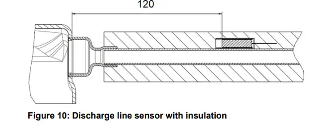
3.7.1 External discharge line temperature sensor
The use of an external discharge sensor is required for all YRH(V)*KTE/KTG horizontal compressors.
Assembly of the discharge line sensor
To ensure proper functioning and to avoid false readings, the discharge line sensor must be installed and insulated according to the procedure and recommendations .hereunder.
- Install the discharge line sensor on the discharge tube 120 mm from the top cap.
- The sensor should be placed on the discharge tube in upward position.
- The wire must not be in contact with the top cap of the compressor or the discharge tube. Care should be taken to route the wires so that they do not touch sharp objects.
- To avoid any impact on tripping temperature by the ambient, the discharge line sensor must be properly insulated.
3.8 Internal pressure relief valve
YRH(V)*KTE/KTG horizontal scroll compressors do not have any internal pressure relief valve. To ensure safe operation, a high-pressure control must be used in all applications.
3.9 Discharge check valve
YRH(V)*KTE/KTG horizontal scroll compressors contain an internal check valve on the discharge connection. The check valve prevents rapid discharge to suction pressure equalisation but it is not entirely gas-tight.
Emerson recommends adding a gas-tight external check valve in the discharge line of the YRH(V)*KTE/KTG compressors in transport applications, to avoid liquid refrigerant migration into the compressor during standstill. The external check valve must be qualified for operation in the discharge line.
3.10 Filter screens![]() CAUTION
CAUTION
Screen blocking! Compressor breakdown! Use screens with at least 0.6 mm openings.
The use of filter screens finer than 30 x 30 mesh (0.6 mm openings) anywhere in the system should be avoided with these compressors. Field experience has shown that finer mesh screens used to protect thermal expansion valves, capillary tubes or accumulators can become temporarily or permanently plugged with normal system debris and block the flow of either oil or refrigerant to the compressor. Such blockage can result in compressor failure.
3.11 Compressor oil return, oil balancing, refrigerant floodback and oil dilution tests
CAUTION
Inadequate lubrication! Bearing and moving parts destruction! Ensure adequate oil return from the system into the compressor at any time. No liquid refrigerant should return to the compressor. Liquid refrigerant dilutes the oil, could wash the oil off the bearings and moving parts and could lead to overheating and compressor failure.
The system piping must be carefully designed to ensure sufficient refrigerant gas velocity, so that oil returns to the compressor at all times and conditions. Individual piping diameter calculation depends on the refrigerant properties, pressure level, mass flow, and density.
Once a new system design is set and assembled, a functional test is required. The functional test includes a qualification for the general system oil return, a refrigerant floodback test and an oil dilution test.
A sample compressor equipped with an external oil sight tube can be ordered from Emerson for lab testing.
Records of the evaporating temperature and the bottom shell temperature shall be taken with a high sampling rate during the entire oil return or oil balance testing and under all tested conditions. The liquid level in the sight tube has to be observed and recorded too. Testing conditions shall include the different operation modes and varying loads. If the system is reversible, tests should be conducted in cooling, heating and defrost modes.
System engineers should review the system design and operation to identify the critical conditions and to check oil return, oil balancing, liquid floodback and oil dilution. To assess individual test results and system behaviour, eg, with regard to oil dilution, please contact the Application Engineering department. Typically, the following situations should be considered:
- general oil return test: testing conditions shall be at full and minimum mass flow and density of suction gas in continuous and frequent start-stop cycling.
- liquid floodback and oil dilution test: all possible transient operation conditions in the system should be checked, eg, compressor frequent start/stop, compressor start after long off time with migration, defrost, switching between the operation modes in reversible systems, load changes, fans or pumps cycling at low load and more. To evaluate the risk of liquid floodback or oil dilution, please refer to the charts in Figures 11 & 12. The bottom shell temperature of the compressor and the evaporating temperature have to be monitored.

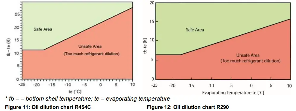
The bottom shell temperature together with the evaporating temperature gives an indication whether liquid refrigerant is returning or diluted in the compressor oil sump. The compressor sump temperature must remain in the (green) safe area, as shown in the charts in Figures 11 & 12. In case of operation in the (red) unsafe area, adjustments are required in order to modify the system design, refrigerant charge or superheat setting of the expansion device(s). The bottom shell temperature should be measured accurately. The thermo-probe must be properly insulated and positioned on the lower side of the compressor shell.
3.12 Suction line accumulator
Due to Copeland scroll’s inherent ability to handle liquid refrigerant, for example in rare flooded start operation, an accumulator is not required in most systems.
The system designer must determine if a suction line accumulator is required with an appropriate test scenario. See section 3.11 “Compressor oil return, oil balancing, refrigerant floodback and oil dilution tests”.
If an accumulator is used, the oil-return orifice should be from 1 to 1.4 mm in diameter for all YRH(V)*KTE/KTG models based on compressor size and compressor floodback results. To protect this small orifice from plugging with system debris, a large-area protective screen no finer than 30 x 30 mesh (0.6 mm openings) is required. Tests have shown that a small screen with a fine mesh can easily become plugged causing oil starvation to the compressor bearings. The size of the accumulator depends upon the operating range of the system and the amount of sub-cooling and subsequent head pressure allowed by the refrigerant control. For the correct selection and size of the suction line accumulator, refer to the manufacturer’s specifications.
Electrical connection
4.1 General recommendations
The compressor terminal box has a wiring diagram on the inside of its cover. Before connecting the compressor, ensure the supply voltage, the phases and the frequency match the nameplate data.
For safety reasons, Emerson recommends that the electrical installation be executed in compliance with standard EN 60204-1 and/or other standards and regulations of application.
When installing YRH(V)*KTE/KTG compressors in a system, the following measures must be taken:
- To ensure the wires are properly terminated, the correct terminal and clamping tool for the selected wire size must be used.
- The ground wiring must conform to local regulations and codes of practice (only the provided parts must be used).
- The grounding screw must be torqued to 2.4 to 2.6 Nm.
- A cable strain-relief device must be added.
- Cable and wires must be protected against sharp edges.
4.2 Electrical installation![]() WARNING
WARNING
Conductor cables! Electrical shock hazard! Shut off power supply before undertaking any task on electrical equipment.![]() WARNING
WARNING
Ignition source in a potentially flammable atmosphere! Fire hazard! The electrical connection of the scroll compressors is not an ignition source during normal operation but could become one if not installed properly according to installation instructions. Ensure correct mechanical and electrical installation. System capacitors may remain charged for several minutes after shutdown. Before starting to work on the electrical installation make sure sparking is not possible. Continuously check if the ambient atmosphere is non-flammable when working on the electrical installation.
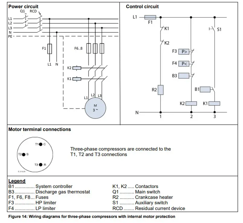
For recommended wiring diagrams, see Figure 14 next page.
NOTE: A contactor K2 has to be used for the safety chain to comply with EN 60335 and EN 60204-1.
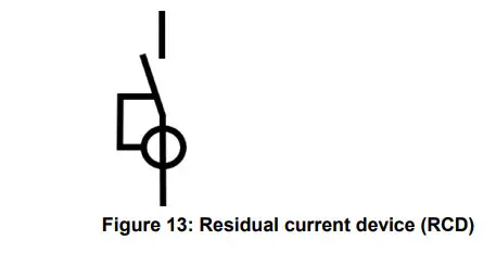
NOTE: For A3 refrigerant (R290) applications, it is mandatory to install a residual current device (RCD) in any electrical system associated with YRH(V)*KTG compressors used.
For A2L refrigerant (R454C) applications, a residual current device (RCD) can be used for additional protection. In both instances, the purpose of the RCD is to detect current leaks to the ground in case of electrical issues, for example with the terminal connection pins or electrical accessories.
Three-phase compressors (TF*):
4.3 Terminal box – IP56![]() WARNING
WARNING
Ignition source in a potentially flammable atmosphere! Fire hazard!
Particular attention must be paid in flammable refrigerant systems as any work on the energized terminals in the compressor terminal box could create an ignition. Do not touch the energized terminals with a tool or cable when the compressor is energized.
Compressors operating with flammable refrigerants shall use only the qualified terminal box supplied with the compressor.![]() CAUTION
CAUTION
Mechanical stress or shock! Overheating! Terminal Fusite damage and leakage! Mechanical stress and shocks to the Fusite must be avoided as they could damage the glass and/or ceramic. This might result in hermetic failure or loss of terminal performance. Precautions are required to prevent striking or bending of pins. Bent or damaged pins may result in loss of hermeticity and/or terminal performance.
Ensure correct connection of cables to the compressor terminal Fusite to avoid local overheating of Fusite pins which might lead to refrigerant leaks.
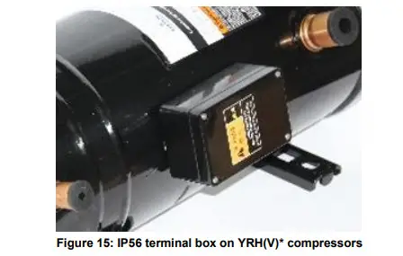
All YRH(V)*KTE/KTG horizontal scroll compressors are equipped with a metal terminal box with an IP56 protection class.
Cable glands have a major influence on the protection class of the terminal box. Emerson strongly recommends using appropriate cable glands according to EN 50262 in order to reach the rated protection class. An example of a correct electrical installation is shown in Figure 15 below.
4.4 Motor winding
YRH(V)*KTE/KTG horizontal scroll compressors have a three-phase induction asynchronous motor.
All three-phase induction motors are connected in star.
4.5 Motor protection
Independently from the internal motor protection, fuses must be installed before the compressor. The selection of fuses has to be made according to EN 60269-1 or EN 60204-1 and compressor maximum operating current (MOC). Failing to install fuses before the compressor or selecting inappropriate fuses may result in compressor failure.
Conventional inherent internal line break motor protection Klixon is provided with all TFD compressor models covered in these guidelines. TX7 variable-speed models do not have an internal protector.
For these TX7 models, motor protection must be handled by setting the correct maximum current value in the inverter.
4.6 Inverter operation
The whole range of fixed-speed horizontal scroll compressor models YRH72KTE/KTG and YRH81KTE/KTG are limited to operation at 50 to 60 Hz.
Variable-speed models YRHV72KTE/KTG and YRH81KTE/KTG can be operated on inverter-derived power over the range of 25 to 100 Hz.
The inverter drives used to power these compressors must comply with the provisions of IEC 600034-17 standard. In particular, the motor input voltage must be limited to 1.35 kV/microsecond line-to-line impulse voltage. These provisions are required to avoid motor insulation breakdown, to limit motor heating and to extend motor lifetime.
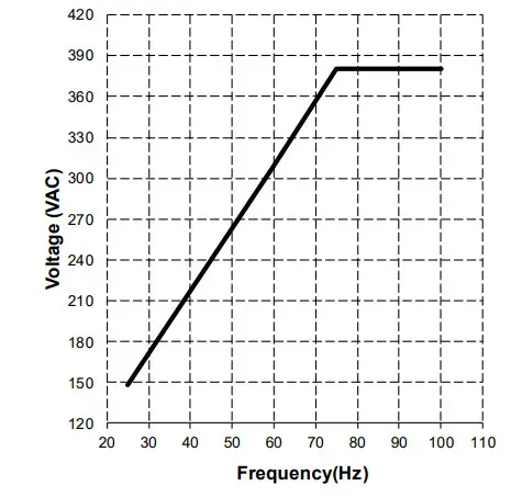
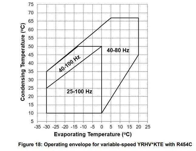
The compressor operating voltage must vary with frequency according to the diagram shown in Figure 16. Matching voltage to frequency according to these guidelines will prevent motor saturation and overheating.
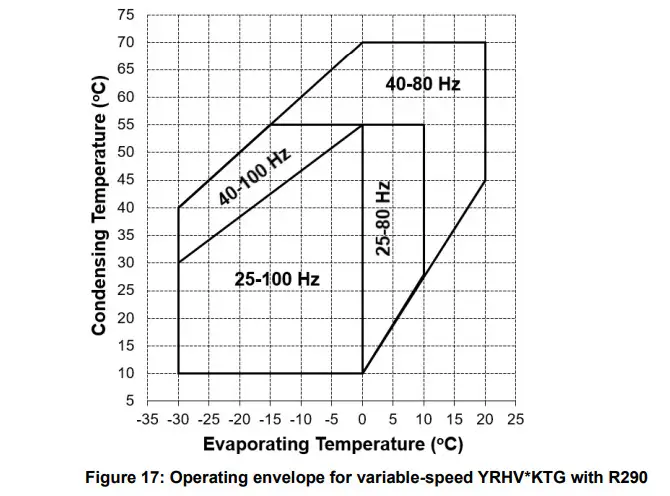
Operating compressor models YRHV*KTE/KTG over a defined frequency range will result in different application envelopes – see Figures 17 & 18. These envelopes are more restricted at lower operating speeds. This is to prevent bearing overloading and overheating of the compressor motor during low-speed operation.
4.7 High-potential testing![]() WARNING
WARNING
High-potential testing in a flammable atmosphere! Fire hazard! Make sure the atmosphere is non-flammable before performing high-potential testing. DO NOT perform any high-potential test when the compressor is charged with flammable refrigerant.![]() WARNING
WARNING
Conductor cables! Electrical shock hazard! Shut off power supply before high-potential testing.![]() CAUTION
CAUTION
Internal arcing! Motor destruction! Do not perform high-voltage or insulation tests if the compressor housing is under vacuum.
Emerson subjects all scroll compressors to a high-voltage test after final assembly. Each motor phase winding is tested according to EN 60335 with 2400 V +/-400 V AC RMS (root mean square).
Since high-voltage tests lead to premature ageing of the winding insulation, additional tests of that nature are not recommended. However, if such a test has to be done for any reason, it shall not be conducted with the compressor charged with refrigerant. Run the test with a lower voltage, as described above. Disconnect all electronic devices, eg, motor protection module, fan speed control, etc prior to testing.
Special attention should be paid when performing a high-potential test and reading the Megohm resistance on A2L and A3 compressors, as such tests can induce an electrical arc and cause a fire hazard.
For this reason, compressors removed from a system with A2L or A3 refrigerant will need to have the oil drained and a nitrogen purge introduced to flush any remaining refrigerant from the compressor prior to high-potential testing and Megohm resistance reading.
Start-up & operation
![]() WARNING
WARNING
Diesel effect! System explosion! The mixture of air and oil at high temperature can lead to an explosion. Avoid operating with air.![]() WARNING
WARNING
Air/flammable refrigerant mixture! Creation of a flammable atmosphere!
Make sure the atmosphere is non-flammable before starting the system.
Ensure that the system contains only refrigerant.
5.1 Strength-pressure test
WARNING
High pressure! Personal injuries! Consider personal safety requirements and refer to test pressures prior to test.
IMPORTANT
System contamination! Bearing malfunction! Use only dry nitrogen for pressure testing. DO NOT USE other industrial gases.
5.1.1 Compressor strength-pressure test
The compressor has been strength-pressure tested in the Emerson factory. Therefore, it is not necessary for the system manufacturer/installer to strength-pressure test the compressor again.
Scroll compressors are divided into two pressure zones. The compressor high-side and low-side maximum allowable pressures PS values have to be respected at all times.
5.1.2 System strength-pressure test
A strength-pressure test of individual sections of the entire system is permitted. Once the compressor is isolated, the rest of the system can be tested with the required pressure values.
The strength-pressure test can also be conducted with the compressor connected, but in that case the two pressure zones of the scroll compressor need to be respected:
- System high-pressure section:
o Define the system high-side PS ≤ compressor high-side PS.
o Isolate the high- and low-pressure sections of the system by closing valves, solenoid valves, expansion valves or by other means.
o Use the internal check valve of the compressor on the discharge side or add an external check valve. To protect the compressor internal check valve, observe a maximum pressure delta of ≤ 40 bar between the high-pressure side and the low-pressure side.
o Activate the check valve with a fast pressure increase. Once the check valve is activated, the rate of pressure increase can be slowed down.
o At this stage the system test pressure of 1.1 x system high-side PS can be applied for a short time.
o During the system test, make sure the pressure inside the compressor does not exceed the maximum PS value, which corresponds to the compressor low-pressure PS. - System low-pressure section:
o Define the system low-side PS ≤ compressor low-side PS.
o The system test pressure of 1.1 x system low-side PS can be applied for a short time.
5.2 Compressor tightness test![]() WARNING
WARNING
High pressure! Personal injuries! Consider personal safety requirements and refer to test pressures prior to test.![]() IMPORTANT
IMPORTANT
System contamination! Bearing malfunction! Use only dry inert gases (for example nitrogen) for leak testing. DO NOT USE other industrial gases.
The compressor has been leak-pressure tested in the Emerson factory.
All compressors get a factory holding charge of dry air (about 0.2 to 0.7 bar, relative pressure. The presence of a holding charge serves as a proof of quality against moisture penetration.
When removing plugs from the compressor, the plugs may pop out due to pressure and oil can spurt.
Any later modification to compressor connections can have an impact on the compressor tightness.
Always leak test the compressor after opening or modifying the connections.
Never add refrigerant to the test gas (as leak indicator).
5.3 System evacuation
Before the installation is put into commission, it has to be evacuated with a vacuum pump. The vacuum pump and all tools have to be approved for an A2L or A3 refrigerant/air mixture. The installation should be evacuated down to an absolute pressure of 3 mbar. Proper evacuation reduces residual moisture to 50 ppm. The installation of adequately sized access valves at the furthest point from the compressor on the suction and liquid lines is advisable. The pressure must be measured using a vacuum pressure gauge on the access valves and not on the vacuum pump; this serves to avoid incorrect measurements resulting from the pressure gradient along the connecting lines to the pump.
Evacuating the system only on the suction side of a scroll compressor can occasionally result in a temporary no-start condition for the compressor. The reason for this is that the floating seal could axially seal with the scroll set, with the higher pressure on the floating seal. Consequently, until the pressures equalise, the floating seal and scroll set can be held tightly together.
The highest demands are placed on the leak-proof design of the installation and on the leak testing methods – refer to, eg, EN 378.
When working on systems already filled with refrigerant, it may be necessary to carry out several evacuation processes. Refrigerant may have dissolved in the refrigerant oil and will only gradually condense out.
5.4 Preliminary checks – Pre-starting![]() WARNING
WARNING
Air/A2L or A3 refrigerant mixture in a potentially flammable or explosive atmosphere! Fire and explosion hazard! Whenever starting up a system charged with A2L or A3 refrigerant, eg, after filling, repair, or maintenance, make sure not to start and operate accidentally in a flammable or explosive atmosphere.
Prepare all details of the system before the installation. If possible, obtain drawings, wiring diagrams, etc. It is ideal to use a check-list but always check the following:
- no explosive atmosphere or flammable gas in the ambient;
- suitable ventilation according to room volume and refrigerant charge;
- visual check of the electrics, wiring, fuses etc;
- visual check of the plant for leaks, loose fittings such as TXV bulbs etc;
- compressor oil level;
- calibration of HP & LP switches and any pressure-actuated valves;
- check setting and operation of all safety features and protection devices;
- all valves in the correct running position;
- pressure and compound gauges fitted;
- correctly charged with refrigerant;
- compressor electrical isolator location & position.
5.5 Charging procedure
WARNING
Air/A2L or A3 refrigerant mixture in a potentially flammable or explosive atmosphere! Fire and explosion hazard! Only use filling equipment designed and approved for use and operation with A2L or A3 refrigerants.
Make sure all connections are tight to avoid leakage. Make sure to fill with pure A2L or A3 refrigerant.
CAUTION
Low suction pressure operation! Compressor damage! Do not operate with a restricted suction. Do not operate with the low-pressure limiter bridged. Do not operate compressor at pressures that are not allowed by the operating envelope. Allowing the suction pressure to drop below the envelope limit for more than a few seconds may overheat scrolls and cause early drive bearing and moving parts damage.
Prior to charging or re-charging, the refrigerant system must be leak- and pressure-tested with appropriate purging gas.
Ensure that the system is grounded prior to charging with refrigerant.
The system shall be liquid-charged through the liquid-receiver shut-off valve or through a valve in the liquid line. The use of a filter dryer in the charging line is highly recommended. Systems shall be liquid-charged on both the high and low sides simultaneously to ensure a positive refrigerant pressure is present in the compressor before it runs. The majority of the charge shall be placed in the high side of the system to prevent bearing washout during first-time start on the assembly line.
Extreme care shall be taken not to overfill the system with refrigerant.
NOTE: The system manufacturer/installer must respect the charge limitations according to valid standards such as EN 378.
5.6 Run-in time
Scroll compressors exhibit a slight decrease in input power during the initial running period.
Published performance ratings are based on calorimeter testing which is carried out after run-in.
Therefore, users should be aware that before the performance specified by EN 12900 is achieved the compressor needs to be run in. Recommended run-in times for YRH(V)*KTE/KTG compressors to attain the published performance are 16 hours at the standard conditions.
5.7 Initial start-up![]() CAUTION
CAUTION
High discharge pressure operation! Compressor damage! Do not use compressor to test opening setpoint of high-pressure cut-out. Internal parts are susceptible to damage before they have had several hours of normal running in.![]() IMPORTANT
IMPORTANT
Oil dilution! Bearing malfunction! It is important to ensure that new compressors are not subject to liquid abuse.
Liquid and high-pressure loads could be detrimental to new bearings. It is therefore important to ensure that new compressors are not subject to liquid abuse and high- pressure run tests. It is not good practice to use the compressor to test the high-pressure switch function on the production line.
Switch function can be tested with nitrogen prior to installation and wiring can be checked by disconnecting the high-pressure switch during the run test.
5.8 Starting behaviour
Due to the design of the Copeland scroll compressors, the internal compression components always start unloaded even if system pressures are not balanced. In addition, since internal compressor pressures are always balanced at start-up, low voltage starting characteristics are excellent for Copeland scroll compressors.
5.9 Rotation direction![]() IMPORTANT
IMPORTANT
Insufficient internal lubrication! Bearing malfunction! Do not operate YRH(V)*KTE/KTG horizontal scroll compressors in reverse rotation. Make sure to electrically connect in the right rotating field and check the running compressor for proper rotation direction.
The lubrication in YRH(V)*KTE/KTG horizontal scroll compressors will only work properly if compressors run in the correct rotation direction. Three-phase compressors will rotate in either direction depending upon the phasing of the power. Since there is a 50-50 chance of connecting power in such a way as to cause rotation in the reverse direction, it is important to include notices and instructions in appropriate locations on the equipment to ensure proper rotation direction when the system is operated and serviced. Observing that suction pressure drops and discharge pressure rises when the compressor is energized allows verification of proper rotation direction.
All three- phase scroll compressors are identically wired internally. Therefore, once the correct phasing is determined for a specific system or installation, connecting properly phased power leads to the identified compressor terminals will ensure proper rotation direction.
5.10 Shell temperature
During normal operation, the discharge gas as well as the compressor top shell and discharge line can reach temperatures up to the maximum discharge gas temperature of 120 °C – see section 3.7 “Discharge gas temperature protection”.
In a failure mode, the discharge gas temperatures can even get higher. Care must be taken to ensure that wiring or other materials that could be damaged by these temperatures do not touch the shell.
5.11 Refrigerant migration
Liquid migration to the compressor and consequent flooded starts after standstill, especially in a cold ambient, must be avoided.
In mobile applications, a crankcase heater might not be effective due to lack of power. This could lead to situations where there will be no voltage present during extended off-cycle periods. A pumpdown cycle in combination with a low leak check valve in the discharge line could be an alternative to reduce off-cycle refrigerant migration to the compressor. This extra low leak check valve must be qualified for discharge line service.
For further support, please contact the Application Engineering department at Emerson or your local Emerson representative.
5.12 Pumpdown cycle
WARNING
Operation below atmospheric pressure! Fire hazard! For applications with A2L or A3 refrigerants, a flammable mixture can form inside the system during operation below atmospheric pressure. Ensure system tightness to prevent any ingress of air. For further details see section 3.5 “System protection for operation below atmospheric pressure”.
CAUTION
Vacuum operation! Compressor damage! Compressor operation outside the operating envelope is not allowed.
The system can be set to pump down for a fixed number of seconds after the setpoint is reached and the liquid line solenoid valve and/or the expansion valve is closed. The exact time should be determined by testing but should not exceed 20 seconds. The system should pump down until the pressure is close to the cut-out pressure of the low- pressure switch. It is not necessary to pump down to pressure values lower than the low-pressure switch cut-out setpoint. If the low-pressure switch opens, the pumpdown should stop immediately. The system should not restart when the lowpressure switch resets; restart should bein response to controller demand. In heat
pumps the 4-way valve should not be allowed to shift after pumpdown.
If a pumpdown cycle is used, a separate external check valve must be added. The scroll discharge check valve is designed to prevent rapid pressure equalisation, but it is not entirely gastight. The check valve might in some cases leak, causing the scroll compressor to recycle more frequently. Repeated short cycling of this nature can result in a low oil situation and consequent damage to the compressor.
For pressure control setting, never set the low-pressure limiter to shut off outside of the operating envelope. To prevent the compressor from running into problems during such faults as loss of charge or partial blockage, the low-pressure limiter shall not be set lower than the minimum suction pressure allowed by the operating envelope.
5.13 Minimum run time
Emerson recommends a maximum of 10 starts per hour. There is no minimum off time because scroll compressors start unloaded, even if the system has unbalanced pressures. The most critical consideration is the minimum run time required to return oil to the compressor after start-up. To establish the minimum run time, a sample compressor equipped with an external oil sight glass is available from Emerson. The minimum on time becomes the time required for oil lost during compressor start-up to return to the compressor sump and to restore a minimal oil level that will ensure oil pick-up through the crankshaft. Cycling the compressor for a shorter period than this, for instance to maintain very tight temperature control, will result in progressive loss of oil and damage to the compressor.
5.14 Shut-off sound
Scroll compressors incorporate a device that minimizes reverse rotation. The residual momentary reversal of the scrolls at shut-off will cause a clicking sound, but it is entirely normal and has no effect on compressor durability.
5.15 Supply frequency and voltage
There is no general release for the fixed-speed horizontal scroll compressor models YRH*KTE/KTG for use with variable-speed AC drives. Only frequencies from 50 to 60 Hz are acceptable.
If the inverter can only deliver a maximum voltage of 400 V, the amps will increase when the speed is above 50 Hz, and this may give rise to nuisance tripping if operation is near the maximum power limit and/or compressor discharge temperature limit.
Variable-speed horizontal scroll compressor models YRHV*KTE/KTG can be applied in the frequency band, as shown in section 4.6 “Inverter operation”.
The last digit of the model motor code indicates which supply frequency and voltage must be applied – see section 2.3 “Nomenclature”.
| 50 Hz | 60 Hz | Code |
| 380-420 V – 3 ph | 460 V – 3 ph | D |
| – | 380 V – 3 ph | 7 |
Table 6: Electrical motor codes for YRH(V)*KTE/KTG compressors
5.16 Oil level
There is no oil sight glass on YRH(V)*KTE/KTG compressors. Consequently, it is difficult to get an indication about the actual oil level in the compressor during operation.
During the system development phase, adequate oil return from the system to the compressor should be evaluated and qualified. For this purpose, a sample compressor for lab testing, equipped with an external oil sight tube, is available from Emerson. A sufficient oil level must be present in the compressor at all times to ensure compressor reliability.
Maintenance & repair
![]() WARNING
WARNING
Conductor cables! Electrical shock hazard! Follow the lockout/tag out procedure and the national regulations before carrying out any maintenance or service work on the system.
Use compressor with grounded system only. Screwed electrical connections must be used in all applications. Refer to original equipment wiring diagrams.
Electrical connections must be made by qualified electrical personnel.![]() WARNING
WARNING
Explosive flame! Fire hazard! Oil-refrigerant mixtures are highly flammable.
Remove all refrigerant before opening the system. Avoid working with an unshielded flame in a refrigerant-charged system.![]() WARNING
WARNING
Ignition source in a potentially flammable or explosive atmosphere! Fire and explosion hazard! When opening a flammable-refrigerant system, the atmosphere could be explosive. All electrical components that are a source of ignition must always be switched off during service and maintenance. Ensure that the surface temperatures of the components never exceed the limits set by the applicable safety standard, eg, EN 378-2.
Air/flammable refrigerant mixture! Fire and explosion hazard! Remove all refrigerant before opening the system. Make sure to remove refrigerant completely from all components such as heat exchangers, refrigerant accumulators, etc. Flush the system and the components with inert gas before undertaking any work and before brazing.![]() WARNING
WARNING
Open flame in a potentially flammable or explosive atmosphere! Fire and explosion hazard! The area shall be checked with an appropriate refrigerant detector prior to and during work on the system, to ensure the technician is aware of a potentially toxic or flammable atmosphere. Ensure that the leak detection equipment being used is suitable for use with all applicable refrigerants.
Personnel performing work on a refrigeration system that involves exposing the pipework shall avoid using any ignition source in a way that could lead to a fire or explosion hazard. All sources of ignition shall be kept sufficiently far from the site of installation, repair, removal or disposal during the entire time when refrigerant could be released into the surrounding space.
Open flames and smoking are strictly forbidden at all times.
During service make sure that:
- the area is well ventilated;
- the materials and equipment used are suitable for use under flammable conditions;
- only non-sparking tools are used;
- antistatic gloves and clothes are used;
- build-up of electrostatic charges is avoided;
- no unshielded or naked flame is used.
If parts of the refrigeration system are charged with flammable refrigerant, make sure that all the valves are tightly closed and that the open pipes after the valves are free of refrigerant and oil.
A risk analysis to evaluate all possible risks shall be carried out by the service technician before any repair work on a flammable refrigerant system.
6.1 Qualification of workers
Personnel working on the maintenance, repair and decommissioning of a flammable refrigerant system shall be adequately trained. Any work procedure affecting safety shall only be executed by qualified and trained personnel in compliance with national or other equivalent certification systems.
Examples of such work procedures include:
- breaking into the refrigerating circuit;
- opening sealed components;
- opening ventilated enclosures…
6.2 Preparation and work procedure
A work procedure shall be provided in the preparation stage. All maintenance personnel and others working at the site shall be instructed on the nature of the work being carried out.
If any work is to be conducted on the refrigeration systems or any associated parts, appropriate fire extinguishing equipment shall be provided. Dry powder or CO2 fire extinguishers are considered appropriate. Confirm that appropriate fire extinguishing equipment is available near the work area. Prior to starting to work on systems containing flammable refrigerants, safety checks are necessary to ensure that the risk of ignition is minimized.
Work shall be undertaken under a controlled procedure so as to minimize the risk of a flammable gas or vapour being present while the work is being performed.
Avoid working on systems filled with flammable refrigerant in a confined space.
6.3 Disassembling system components
When disassembling system components please follow the main steps described hereunder:
- Recover refrigerant and evacuate system using an A2L- or A3-dedicated recovery unit and vacuum pump. All the refrigerant shall be recovered to avoid significant release. Ensure that the outlet of the vacuum pump is not close to any potential ignition source and that ventilation is available.
- Flush system with inert gas (dry nitrogen). Compressed air or oxygen shall not be used for purging refrigerant systems.
- For A2L and A3 refrigerant systems, the procedure of evacuation and flushing with oxygen-free nitrogen may need to be repeated until no refrigerant is present in the system. When the final oxygen-free nitrogen charge is used, the system shall be vented down to atmospheric pressure to enable work to take place.
- Disassemble components with a cutting tool.
- Drain, recover and dispose of compressor oil as appropriate.
To disconnect:
- Using a pipe cutting tool, cut off the suction and discharge lines in such a manner that the new compressor can easily be re-connected into the system.
- Heat joint areas 2 and 3 slowly and uniformly until the braze material softens and the tube end can be pulled out from the fitting.
Figure 19: Tube connecting areas
To reconnect:
- Recommended brazing material: Silfos with minimum 5 % silver or silver braze used on other compressors.
- Due to the different thermal properties of steel and copper, brazing procedures may have to be changed from those commonly used.
NOTE: Since the discharge stub contains a check valve, care must be taken not to overheat it to prevent brazing material from flowing into it.
6.4 Exchanging the refrigerant![]() WARNING
WARNING
Air/flammable refrigerant mixture in a potentially flammable or explosive atmosphere! Fire and explosion hazard! In any case avoid air/A2L or A3 mixture in the refrigeration system. Make sure that the system is filled with pure A2L or A3 refrigerant. In the event that the refrigerant needs replacing, the charge should be recovered using A2L- or A3-qualified refrigerant recovery unit and recycling bottles.
CAUTION![]() Low suction pressure operation! Compressor damage! Do not operate with a restricted suction. Do not operate with the low-pressure limiter bridged.
Low suction pressure operation! Compressor damage! Do not operate with a restricted suction. Do not operate with the low-pressure limiter bridged.
Do not operate compressor at pressures that are not allowed by the operating envelope. Allowing the suction pressure to drop below the envelope limit for more than a few seconds may overheat scrolls and cause early drive bearing and moving parts damage.
For qualified refrigerants and oils, see section 2.5.1 “Qualified refrigerants and oils”.
It is not necessary to replace the refrigerant unless contamination, for example due to an error such as topping up the system with a non-condensable gas or incorrect refrigerant, is suspected. To verify correct refrigerant composition, a sample can be taken for chemical analysis. A check can be made during shutdown by comparing the refrigerant temperature and pressure using precision measurements at a location in the system where liquid and vapour phases are present and when the temperatures have stabilised.
6.5 Replacing a compressor
CAUTION![]() Inadequate lubrication! Bearing destruction! For systems with a refrigerant accumulator, exchange the accumulator after replacing a compressor with a burned-out motor. The accumulator oil return orifice or screen may be plugged with debris or may become plugged. This will result in starvation of oil to the new compressor and a second failure.
Inadequate lubrication! Bearing destruction! For systems with a refrigerant accumulator, exchange the accumulator after replacing a compressor with a burned-out motor. The accumulator oil return orifice or screen may be plugged with debris or may become plugged. This will result in starvation of oil to the new compressor and a second failure.
Remove refrigerant and oil completely from the replaced compressor.
6.5.1 Compressor replacement
If an A2L- or A3-refrigerant compressor is to be replaced, the oil has to be drained out of the compressor and the compressor should be flushed with dry nitrogen. DO NOT close the stubs with plugs.
In case of motor burnout, the majority of the contaminated oil will be removed with the compressor.
The rest of the oil is cleaned through the use of suction and liquid line filter-dryers. A 100 % activated alumina suction line filter-dryer is recommended but must be removed after 72 hours. When a compressor is exchanged in the field, a major portion of the oil may still be present in the system.
While this will not affect the reliability of the replacement compressor, the extra oil will add to rotor drag and increase power usage.
6.5.2 Start-up of a new or replacement compressor
Rapid charging only on the suction side of a scroll-equipped system can occasionally result in a temporary no-start condition for the compressor. The reason for this is that, if the flanks of the scrolls happen to be in a sealed position, rapid pressurisation of the low side without opposing high-side pressure can cause the scrolls to seal axially. As a result, until the pressures eventually equalise, the scrolls can be held tightly together preventing rotation. The best way to avoid this situation is to charge on both the high and low sides simultaneously at a rate which does not result in axial loading of the scrolls.
A minimum suction pressure specified in the published operating envelope must be maintained during charging. Allowing the suction pressure to drop below that value may overheat the scrolls and cause early drive bearing and moving parts damage. Never install a system in the field and leave it unattended when it has no charge, a holding charge, or with the service valves closed without securely electrically locking out the system. This will prevent unauthorised personnel from accidentally operating the system and potentially ruining the compressor by operating with no refrigerant. Do not start the compressor while the system is in a deep vacuum. Internal arcing may occur when a scroll compressor is started in a vacuum causing burnout of the internal lead connections.
6.5.3 Compressor return procedure
If a compressor has to be returned to the manufacturer for analysis, the refrigerant and the oil have to be removed completely. For the shipping process, all compressor connections must remain open and warning stickers for flammable refrigerant must be placed on the shipping box.
- During the entire working procedure continuously check if the ambient atmosphere is flammable.
If a flammable atmosphere is detected, ensure proper ventilation of the working space and immediately cut-off the power supply. - Resume working after the atmosphere is no longer dangerous.
- Recover the refrigerant from the system using a suitable recovery unit. During this action, the compressor crankcase heater could be energized – immediately de-energize in case a flammable atmosphere is detected.
- Recover to 3 mbar absolute pressure or lower. For best results and to recover also the refrigerant dissolved in the oil, run the recovery unit two or three times as necessary.
- Flush the whole system with oxygen-free dry nitrogen.
- Open the system with a cutting tool and purge the entire system with dry nitrogen.
- Disassemble the compressor with a cutting tool. Drain and recover compressor oil properly. Purge the compressor with dry nitrogen again for a few minutes.
- The compressor should be returned free of oil and with connections open – do not close connections with plugs.
- Collect and secure the oil properly. Provide information about the quantity of oil drained from the compressor and its colour. Ideally, send a good picture.
- Dispose of the oil according to local rules and regulations.
- Use a proper cardboard box package when preparing the compressor for shipment. Place warning icons on each side and on the top of the box. Mention the following message on the box: “Warning! Flammable A2L or A3 refrigerant compressor for analysis”.
- The compressor must be kept in the horizontal position – mark the box accordingly.
- If more than one compressor have to be returned, each compressor must be packed individually.
NOTE: Check with the transport company that all the requirements that apply to such shipments are complied with.
6.6 Lubrication and oil removal![]() WARNING
WARNING
Air/Flammable refrigerant mixture in a flammable or explosive atmosphere! Fire and explosion hazard! Use a suitable recovery unit and recycling bottles also for oil disposal as A2L or A3 refrigerant may still be dissolved in the oil.![]() CAUTION
CAUTION
Chemical reaction! Compressor destruction! Do not mix ester oils with mineral oil and/or alkyl benzene when used with chlorine-free (HFC) refrigerants.
The compressor is supplied with an initial oil charge. The standard oil charge is RL 32 3MAF for YRH(V)*KTE models and RLF 68EP for YRH(V)*KTG models. See nameplate for original oil charge shown in litres. A field recharge is approximately 0.05 to 0.1 litre less.
Both POE polyolester oil and PAG polyalkylene glycol oil are hygroscopic. Only brief exposure to ambient air is needed to absorb sufficient moisture to make it unacceptable for use in a refrigeration system. Since POE and PAG oils hold moisture more readily than mineral oil it is more difficult to remove it through the use of vacuum. In comparison with POE oil, PAG oil is even more hygroscopic.
However, in systems with PAG oil, the same measures to prevent moisture ingress and removal (for example minimize the contact with air, use of appropriate vacuuming methods, use of a filter-dryer, etc…) can be used as in systems with POE oil. The compressors supplied by Emerson contain oil with low moisture content, which may rise during the system assembling process. Therefore, it is recommended that a properly sized filter-dryer be installed in all POE/PAG systems. This will maintain the moisture level in the oil to less than 50 ppm. If oil is charged into a system, it is recommended to use POE/PAG with a moisture content no higher than 50 ppm.
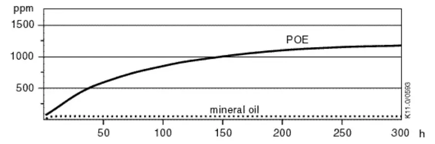
Figure 20: Absorption of moisture in ester oil in comparison to mineral oil in ppm by weight at 25 °C and 50 % relative humidity (h= hours)
If the moisture content of the oil in a refrigeration system reaches unacceptably high levels, corrosion and copper plating may occur. The system should be evacuated down to 3 mbar. If there is uncertainty as to the moisture content in the system, an oil sample should be taken and tested for moisture. Sight glass/moisture indicators currently available can be used with the HFC refrigerants and lubricants; however, the moisture indicator will just show the moisture content of the refrigerant.
The actual moisture level of POE/PAG would be higher than the sight glass indicates. This is due to the high hygroscopicity of the POE and PAG oils. To determine the actual moisture content of the lubricant, samples have to be taken from the system and analysed.
NOTE: YRH(V)*KTE/KTG horizontal scroll compressors are fitted with an internal oil pump.
6.7 Oil additives
Although Emerson cannot comment on any specific product, from our own testing and past experience, we do not recommend the use of any additives to reduce compressor bearing losses or for any other purpose. Furthermore, the long-term chemical stability of any additive in the presence of refrigerant, low and high temperatures, and materials commonly found in refrigeration systems is complex and difficult to evaluate without rigorously controlled chemical laboratory testing. The use of additives without adequate testing may result in malfunction or premature failure of components in the system and, in specific cases, in voiding the warranty on the component.
Dismantling & disposal
Removing oil and refrigerant:
- Do not disperse refrigerant in the environment.
- Use the correct equipment and method of removal.
- Dispose of oil and refrigerant in accordance with national legislation and regulations.
Dispose of compressor in accordance with national legislation and regulations.
References
Please visit www.climate.emerson.com/en-gb for free download of Application Guidelines and Technical Information.
Performance and technical data:
The latest version of Copeland Select software with performance data and technical data is available from the webpage www.climate.emerson.com/en-gb.
Spare parts and accessories:
Visit www.climate.emerson.com/en-gb/tools-resources for an online version of the Emerson spare parts and accessories software.
Appendix 1: Tightening torques
| Connection | Torque (Nm) |
| M10 | 45 – 55 |
| Mounting bolts 5/16″, M9 | 27 max |
| Mounting bolts M8 | 13 ± 1 |
| Terminal block screw | 2.8 |
| Ground screw | 2.3 |
DISCLAIMER
- The contents of this publication are presented for informational purposes only and are not to be construed as warranties or guarantees, express or implied, regarding the products or services described herein or their use or applicability.
- Emerson Climate Technologies GmbH and/or its affiliates (collectively “Emerson”), as applicable, reserve the right to modify the design or specifications of such products at any time without notice.
- Emerson does not assume responsibility for the selection, use or maintenance of any product.
Responsibility for proper selection, use and maintenance of any Emerson product remains solely with the purchaser or end user. - Emerson does not assume responsibility for possible typographic errors contained in this publication.
UK & IRELAND
Unit 17, Theale Lakes Business Park
Reading, Berkshire RG7 4GB
Tel: +44 1189 83 80 00
Fax: +44 1189 83 80 01
[email protected]
For more details, see www.climate.emerson.com/en-gb
Connect with us: facebook.com/EmersonCommercialResidentialSolutions
Emerson Commercial & Residential Solutions
Emerson Climate Technologies GmbH – Pascalstrasse 65 – 52076 Aachen, Germany
Tel. +49 (0) 2408 929 0 – Fax: +49 (0) 2408 929 570 – Internet: www.climate.emerson.com/en-gb
The Emerson logo is a trademark and service mark of Emerson Electric Co. Emerson Climate Technologies Inc. is a subsidiary of Emerson Electric Co.
Copeland is a registered trademark and Copeland Scroll is a trademark of Emerson Climate Technologies Inc.. All other trademarks are property of their respective owners.
Emerson Climate Technologies GmbH shall not be liable for errors in the stated capacities, dimensions, etc., as well as typographic errors. Products, specifications, designs and technical data contained in this document are subject to modification by us without prior notice. Illustrations are not binding.
© 2019 Emerson Climate Technologies, Inc.


