![]()
![]() Communication Technology RTCD905 DOCSIS3.0 Residential Gateway
Communication Technology RTCD905 DOCSIS3.0 Residential Gateway
User Manual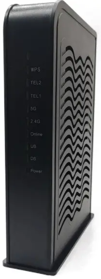
To our distinguished customers:
Congratulations on your purchase of the Radiotech Cable Modem Gateway. The RTCD905_H6W4 is designed keeping in mind a Service Providers need to deploy cost-effective and reliable high-speed wireless data and voice services. The RTCD905_H6W4 provides superior RF performance over DOCSIS 3.0 specifications to operate on challenging RF networks besides offering enhanced wireless coverage.
This user manual contains all the information you need to install and configure your new RTCD905_H6W4 Cable Modem Gateway. Please read it carefully first before using it.
Key features
- DOCSIS 3.0 compliant design
- Up to 24 downstream channels and 8 upstream channels
- 3T3R 2.4GHz 11n + 4T4R 5GHz 11ac dual-band concurrent with 400Mbps+1300Mbps PHY data rate
- Multicast, concatenation, fragmentation, BPI, BPI+ support
- Remote management via SNMP, telnet, and Web support
- Maximum 64 users support
 Safety and Warnings
- Do not put the device on an unstable desktop.
- Keep the device in a dry and clean place.
- Keep the device away from liquid、dust、magnetic and excessive heat.
- Keep the device working under the specified voltage supply
- Do not put any stuff, or liquid into the holes on the device.
- Do not put heavy stuff on the device
- Do keep the device in the ventilation environment, and do not cover it with a cloth when working.
- Make sure that the device is working under the specified voltage supply
- Do not clean the surface of the device with chemicals
- Do not disassembly the device by your ownable Mod
Unpacking Package Contents
Unpack the items in your Cable Modem Gateway contents and confirm that no items are missing or damaged. Your package should include:
- One RTCD905_H6W4 Cable Modem Gateway
- One Power adapter (12V/2.3A)
- One Category 5 Ethernet cable
- One phone cable
- One User Manual
If any items are missing or damaged, please contact your place of purchase. Keep the carton, including the original packing material, in case you need to store the product or return it.
Interface Description:
| Item | color | action | Description |
| Power | Green | On/Off | Power status on/off |
| DS | Green/Blue | Green Blink | Searching for downstream |
| Green ON | Downstream channel locked | ||
| US | Green/Blue | Green Blink | Searching for upstream |
| Green ON | Upstream Channel locked | ||
| ONLINE | Green | Blink | Registering to Front-End |
| ON | Modem is online | ||
| WPS | Green | Blink | The WPS function is activated. (1) |
| 2.4G | Green | Off | The 2.4G band WIFI RF is OFF |
| On | The 2.4G band WIFI RF is ON |
| Blink | The 2.4G band WIFI RF is transporting | ||
| 5G | Green | Off | The 5G band WIFI RF is OFF |
| On | The 5G band WIFI RF is ON | ||
| Blink | The 5G band WIFI RF is transporting |
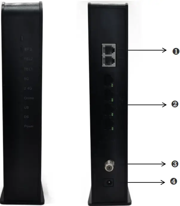
Interface Instructions
| Item | Description |
| 1—LAN1/LAN2/LAN3/LAN4 | RJ-45 Ethernet port1/port2/port3/prot4 |
| 2—RESET | RESET to default the Router |
| 3—RF-IN | RF input |
| 4—POWER | Power adapter DC Jack |
Restoring Factory Defaults
Using the Reset button on the Rear Panel, you can power cycle the Gateway and return it to its original factory default settings. As a result, any changes you made to the Gateway’s default settings will be removed. (Generally when you forget the name&password)
- Leave the power plugged into the Gateway.
- Find the Reset button on the back panel, then press and hold it for at least 10 seconds
- Release the Reset button
Specification
Cable Modem Specification
| Section | Parameter | Specification | ||||||
| Interface | Input | F-Type RF connector | ||||||
| Ethernet | 4 * 10/100/1000 BASE-T | |||||||
| Flash | 128M Bytes | |||||||
| RAM | 256M Bytes DDR3 | |||||||
| Down stream | Frequency Range | NA | 108 MHz to 1002 MHz | |||||
| Euro | 108 MHz to 1002MHz | |||||||
| Modulation | 64QAM/256QAM | |||||||
| Input signal level | -17dBmV to +13dBmV (64QAM) -13dBmV to +17dBmV (256QAM) | |||||||
| Data Rate | NA | 24 Maximum downstream channel 9600Mbps | ||||||
| Euro | 24 Maximum downstream channel 1200Mbps | |||||||
| Bandwidth | NA | 6MHz(ALpha=0.18 for 64QAM) | ||||||
| 6MHz(ALpha=0.12 for 256QAM) | ||||||||
| Euro | 8MHz(ALpha=0.15 for 64QAM &256QAM) | |||||||
| Capture Bandwidth | Maximum support 8 channel bonding | |||||||
| Input Impedance | 75 ohms | Input Return Loss | >8dB | |||||
| Up stream | Frequency Range | NA | 5 MHz to 82MHz | |||||
| Euro | 5 MHz to 85MHz | |||||||
| Output signal level | Modulation | Minimum power | Single-channel maximum power | Four-channel maximum power | ||||
| 1280Ksym/s | 5120Ksym/s | TDMA/S-CDMA | TDMA/S-CDMA | |||||
| QPSK | 17 dBmV | 23dBmV | 61/56dBmV | 55/53dBmV | ||||
| 8QAM | 17 dBmV | 23 dBmV | 58/56 dBmV | 52/53 dBmV | ||||
| 16QAM | 17 dBmV | 23 dBmV | 58/56 dBmV | 52/53 dBmV | ||||
| 32QAM | 17 dBmV | 23 dBmV | 57/56 dBmV | 51/53 dBmV | ||||
| 64QAM | 17 dBm | 23 dBm | 57/56 dBmV | 51/53 dBmV | ||||
| 128QAM(S-CDMA) | 17 dBm | 23 dBm | -/56 dBmV | -/53 dBmV | ||||
| Modulation Rate | 160Ksym/s,320Ksym/s.640 Ksym/s,1280 Ksym/s ,2560Ksym/s,5120Ksym/s | |||||||
| Data Rate | 8 Maximum upstream channel 240Mbps | |||||||
| Output Impedance | 75 ohms | Output Return Loss | >8dB | |||||
WiFi Router Specification
| Hardware Features | |
| Antennas | Internal 5 antennas |
| Wireless Features | |
| WIRELESS STANDARDS | IEEE 802.11a/b/g/n/ac |
| FREQUENCY | 2.4G /5G dual-band |
| PHY RATE | Dual-band concurrent Up to 1700Mbps PHY data rate |
| SIGNAL RATE | 2.4G 11n: Up to 400Mbps@256QAM (dynamic) |
| 11g: Up to 54Mbps(dynamic) | |
| 11b: Up to 11Mbps(dynamic) | |
| 11ac: Up to 1300Mbps(dynamic) | |
| Modulation | 11n: BPSK, QPSK, 16QAM, 64QAM with OFDM |
| 11g: BPSK, QPSK, 16QAM, 64QAM, OFDM | |
| 11b: DQPSK, DBPSK, DSSS, CCK | |
| WIRELESS TRANSMIT POWER | 18dBm |
| RECEIVE SENSITIVITY | 270M: -68dBm@10% PER |
| 130M: -68dBm@10% PER | |
| 108M: -68dBm@10% PER | |
| 54M: -68dBm@10% PER | |
| 11M: -85dBm@8% PER | |
| 6M: -88dBm@10% PER | |
| 1M: -90dBm@8% PER | |
| WIRELESS FUNCTIONS | Enable/Disable Wireless Radio, Transmit Power Control, Wireless Statistics |
| WIRELESS | WPA-PSK / WPA2-PSK |
| Software Features | |
| WAN TYPE | DHCP/Static IP/PPPoE |
| PORT FORWARDING | Virtual Server, Port Triggering, UPnP, DMZ |
| VPN PASS-THROUGH | PPTP, L2TP, IPSec |
| FIREWALL SECURITY | IP Address Filter/MAC Address Filter/URL Filter |
| ACCESS CONTROL | Device Black list |
| IPV6 | supported |
| TR069 | Supported |
EMTA Specification
| VOIP Features | Signaling: MGCP, SIP |
| Codecs: G.711a,G.711u,G.723,G.726,G.729ab | |
| Advanced Services: Call waiting Caller Identification Call forwarding Call transferring CLIP (Calling Line Identification Presentation) CLIR (Calling Line Identification Restriction) 3-way conference Functionality: T.38, Echo cancellation G.168, VAD, Silence Suppression, Jitter Buffer, CNG Interop with main market soft switches |
General Specification
| Section | Specification |
| Dimensions | 222mm (W) x160mm (H) x52mm (D) |
| Power Supply | Input :100~240V,50/60Hz: |
| Output: 12V 5% 2.5A(2A for ECV3040M/ECV3040S) | |
| Working Environment | Operating free-air temperature range 0°C to +40 °C |
| Storage -20°C to +85 °C |
Quick Hardware Setup
- First, connect the RF Coaxial Cable of your service provider to your Cable Modem’s RF-In.
- Power on the Cable Modem after connecting the 12V DC power adaptor which is supplied with the modem to the Cable Modem’s power input and switch On the power outlet.
- If you would like to connect your PC/Laptop wired to Modem, connect the supplied CAT5 Cable to the ethernet port of your PC/Laptop and the LAN port of the Cable Modem.
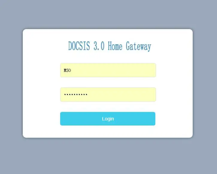
Router Setup Wizard
- Login in the setup GUI.
Open any of the web browsers (Internet Explorer, Mozilla Firefox, Google Chrome, etc.) in your system.
Type the IP address “192.168.20.1” in the address space of your browser as shown below and press Enter. The login page appears.
Since this is the first-time login, type `MSO’ in the “technician” fields and click on `Log In’. Do note that ‘admin’ is a default password.
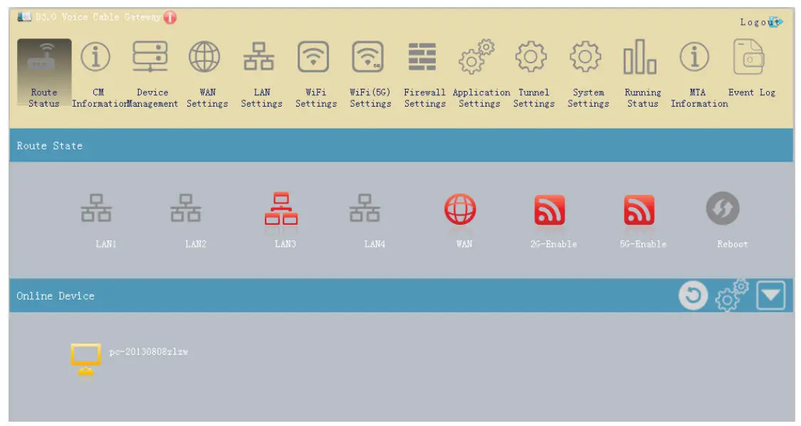
- Router Status
Once you are logged in, you can access to the Router Status Gui. You can check the interface’s working status.
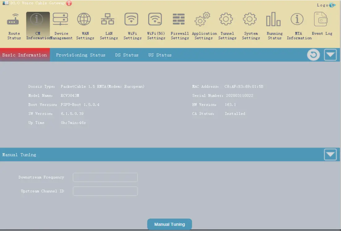
- CM Information
You can get the CM information on this menu.
- Device Management
You can manage the end devices on this menu.
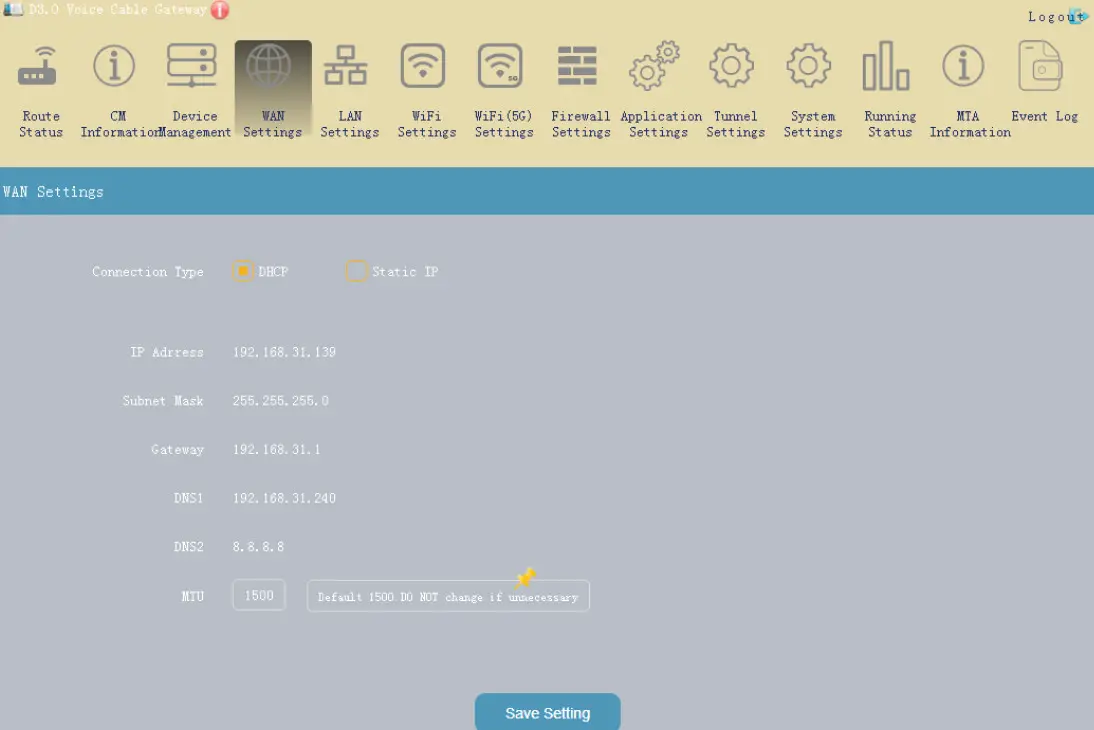
- WAN Settings
You can set the WAN function on this menu.
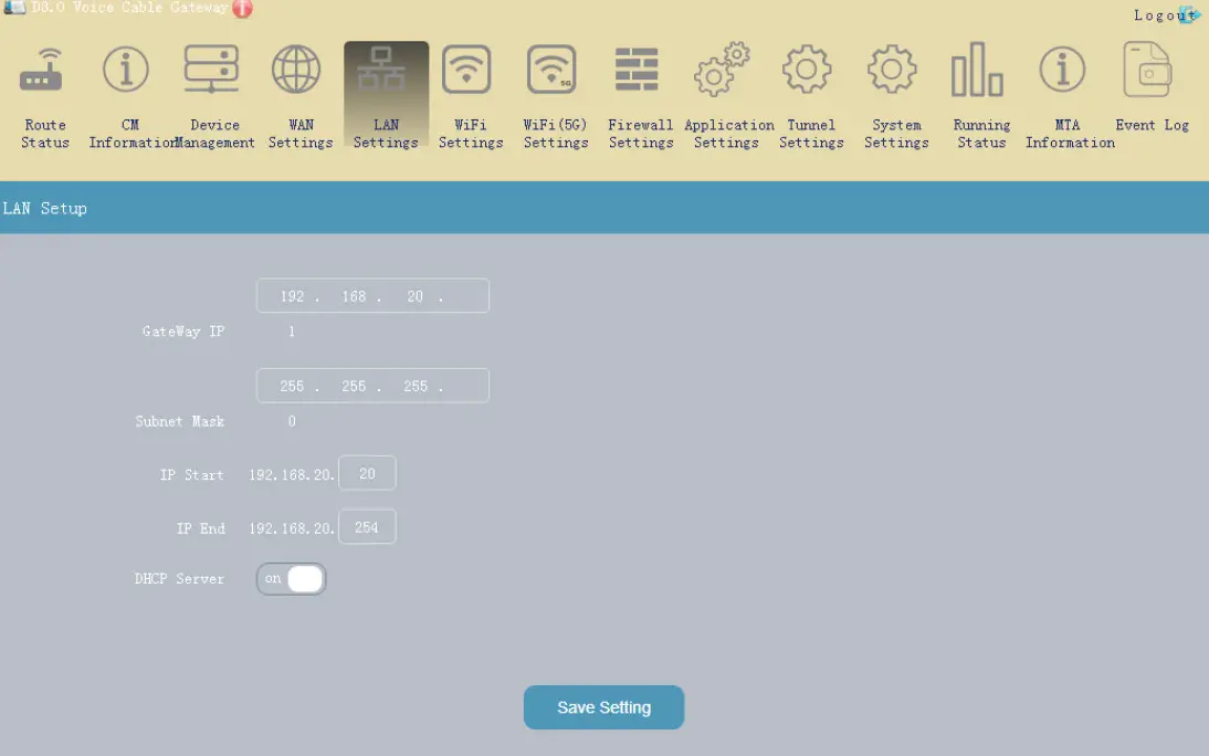
- LAN settings
You can be setting the LAN IP on this menu.
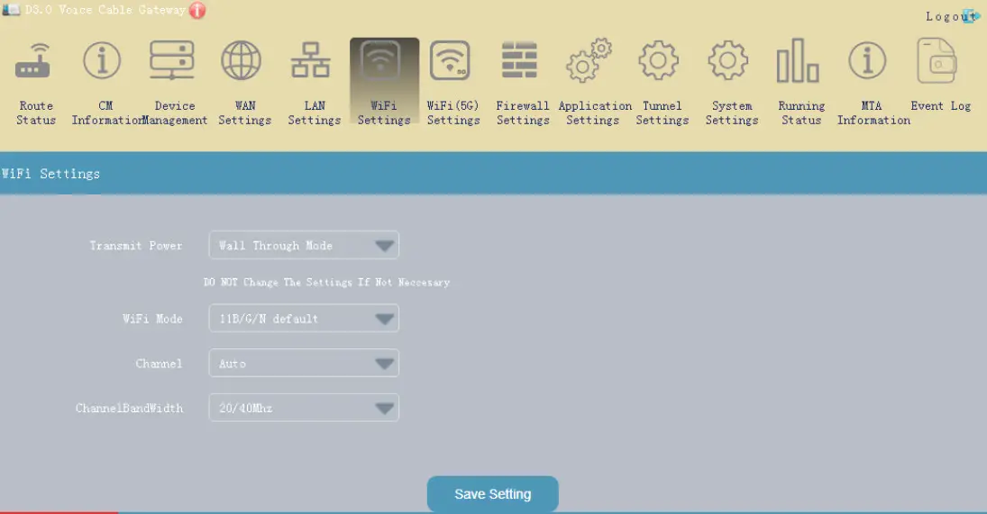
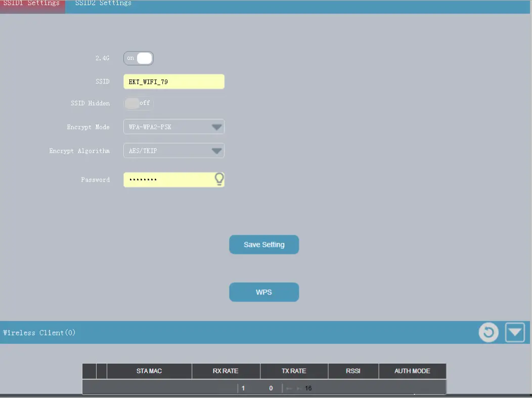
- WiFi/WiFi(5G) settings
You can set the wifi parameters on these menus

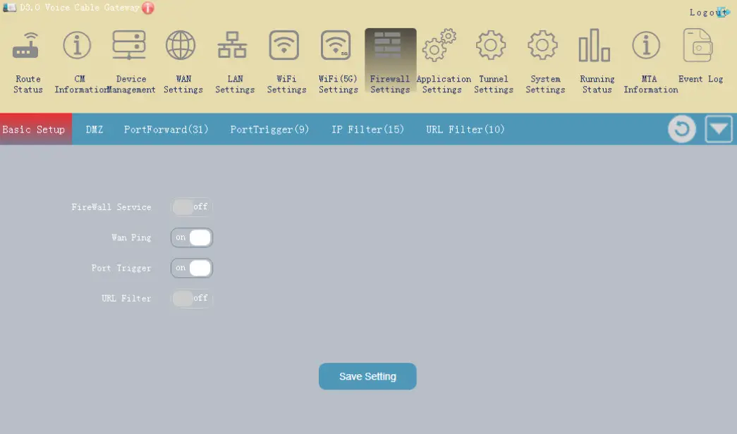
- Firewall Settings
You can access firewall settings at this menu.
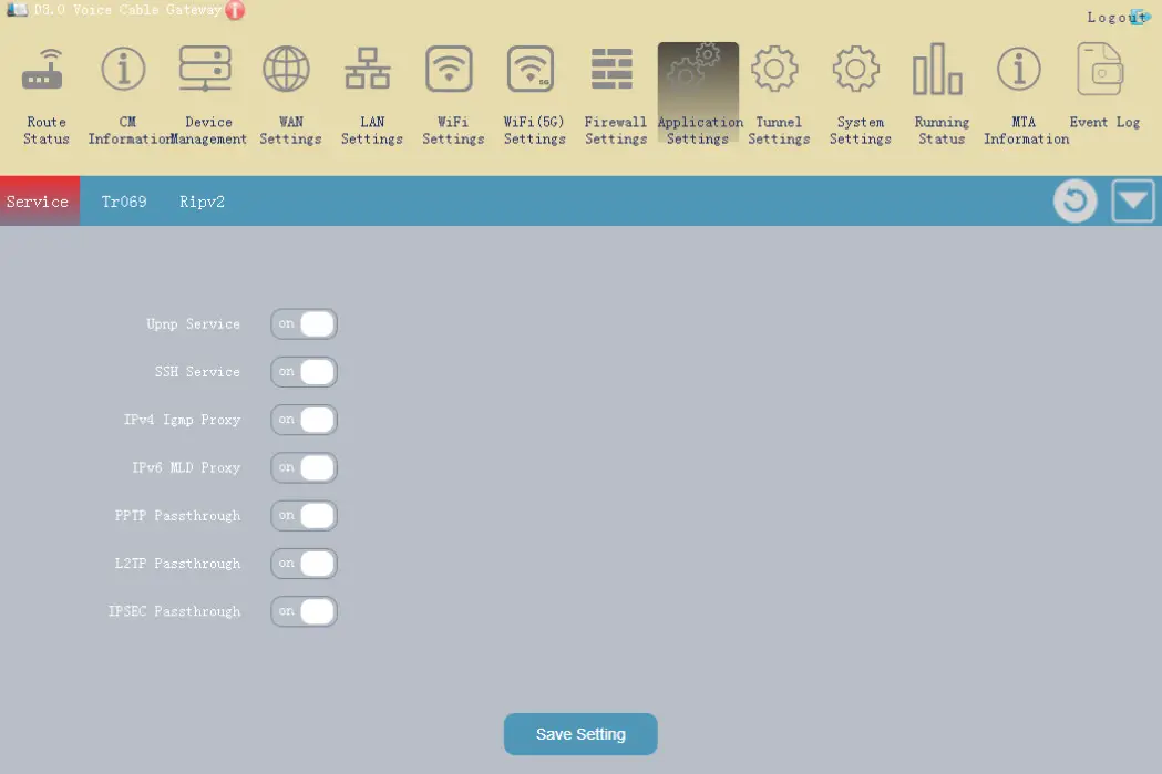
- Application Settings
You can set some particular functions on the menu.
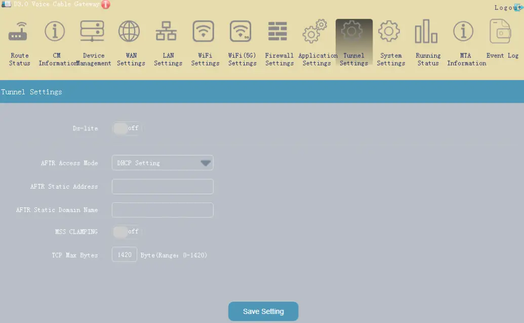
- Tunnel Settings
You can access DS-LITE functions on this menu.
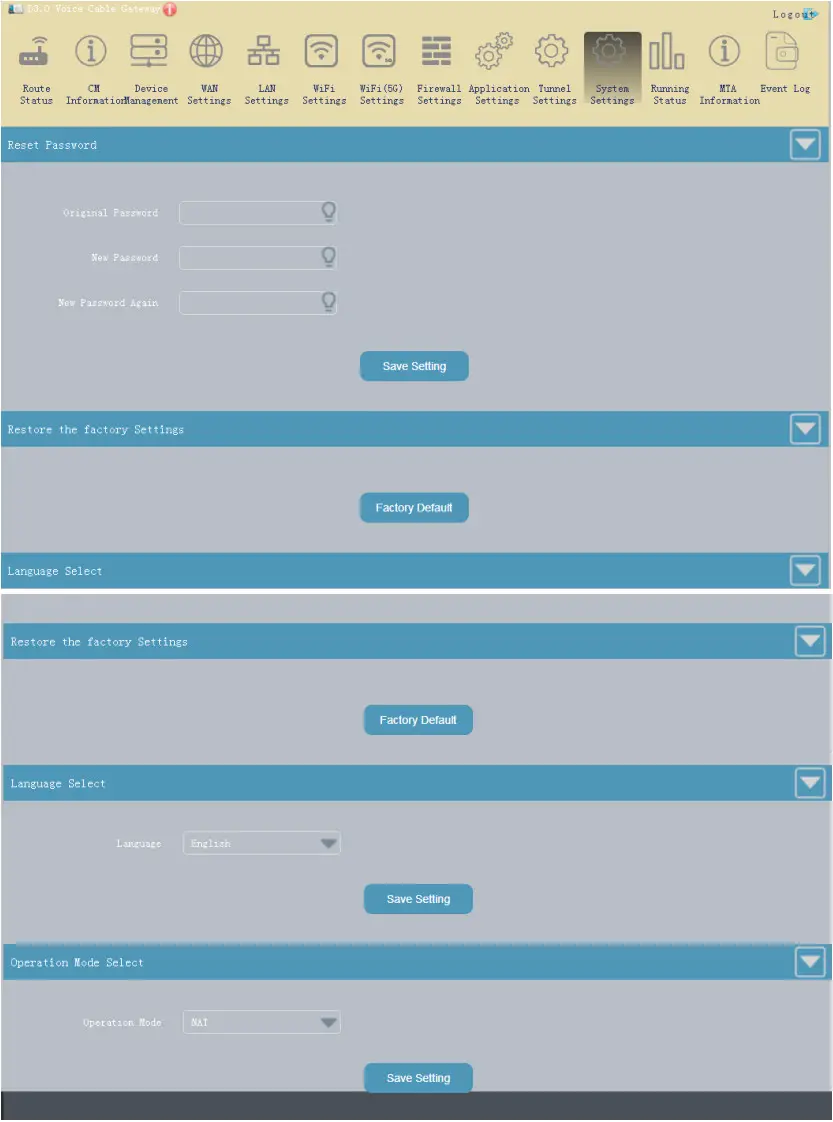
- System Settings
You can some system changes on this menu.
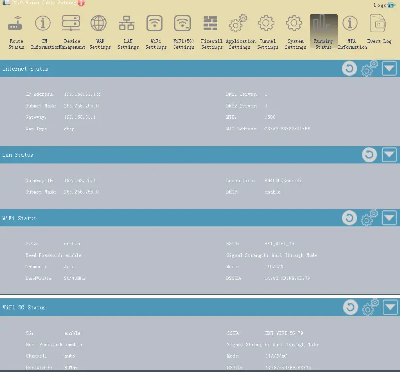
- Running Status
This Page shows the running status information.
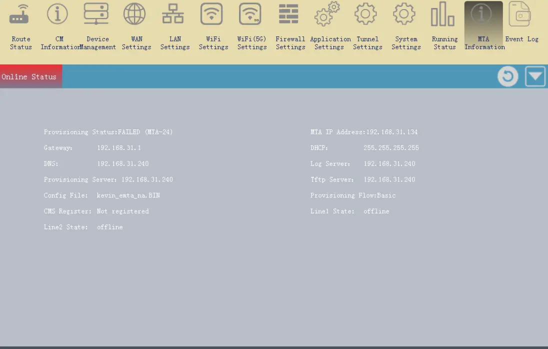
- MTA Information
This page shows the MTA running status information.
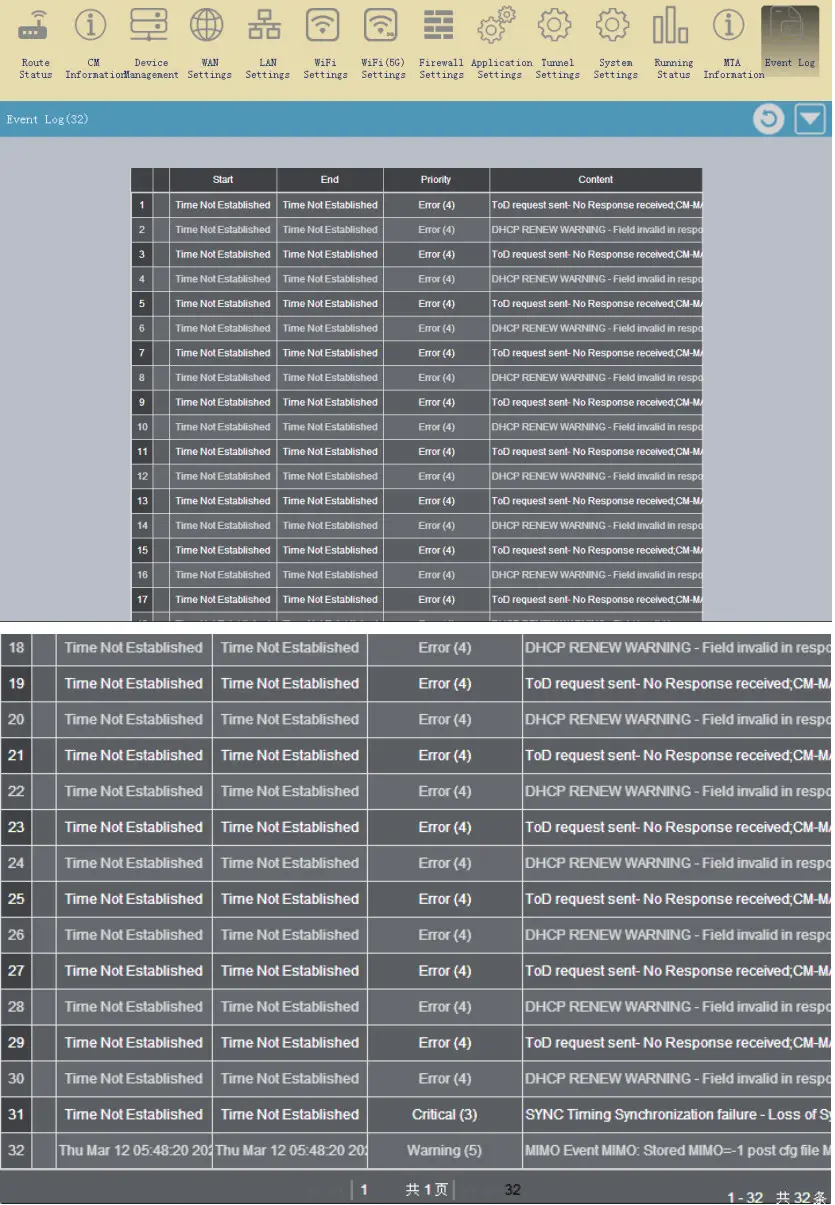
- Event Log
This page shows the Event Log record.

Useful Q & A
Q: Why is Power LED off?
➢ Check your power supply
➢ Plug and unplug your power supply t
Q: Why is Ethernet LED off?
➢ Check your CAT-5 wire.
➢ Check the connection of your RJ-45 to CAT-5 wire
➢ Check your network card on your computer
Q: Why is Online LED off?
➢ Check the connection of your RF-cable to the device
➢ Check the cable-network function is available
Q: Should I turn off the device when I am off of Internet?
➢ The device has been specially designed to operate for several years. It does not need to turn off the power. However, if you do not use it, it is recommended to turn off the power to extend the life of the device. DO NOT unplug the cable directly, you should turn off the related electrical outlet, then unplug the cable.
Q: How to find what causes the device not to boot?
➢ The LEDS Status of the device indicator can reflect whether the device boot normally. If the status indicator is not displayed correctly, refer to the following steps :
➢ Make sure that the Cable Modem and CATV coaxial cable connections are secure, and there is no damage, loose joints, etc.。
➢ Check if cable TV reception is normal if the effect of television programs is significantly worse than the program or simply watch, call your cable customer service center.
➢ Check Power adapter is connected correctly to 220V AC and to the device
➢ Turn off the power, restart the device
Q: Can multiple computers use one device?
➢ At most 16 equipment can connect to the device, but also the MSO setup determines the capacity
FCC Statement
Changes or modifications not expressly approved by the party responsible for compliance could void the user’s authority to operate the equipment.
This equipment has been tested and found to comply with the limits for a Class B digital device, pursuant to Part 15 of the FCC Rules. These limits are designed to provide reasonable protection against harmful interference in a residential installation. This equipment generates uses and can radiate radio frequency energy and, if not installed and used in accordance with the instructions, may cause harmful interference to radio communications. However, there is no guarantee that interference will not occur in a particular installation. If this equipment does cause harmful interference to radio or television reception, which can be determined by turning the equipment off and on, the user is encouraged to try to correct the interference by one or more of the following measures:
- Reorient or relocate the receiving antenna.
- Increase the separation between the equipment and receiver.
- Connect the equipment into an outlet on a circuit different from that to which the receiver is connected.
- Consult the dealer or an experienced radio/TV technician for help
This device complies with part 15 of the FCC rules. Operation is subject to the following two conditions
- This device may not cause harmful interference, and
- This device must accept any interference received, including interference that may cause undesired operation.
This equipment complies with FCC radiation exposure limits set forth for an uncontrolled environment. This equipment should be installed and operated with a minimum distance of 20cm between the radiator & your body.
![]()


