TOPWAY LM6063AFW-A LCD Module
Product Information
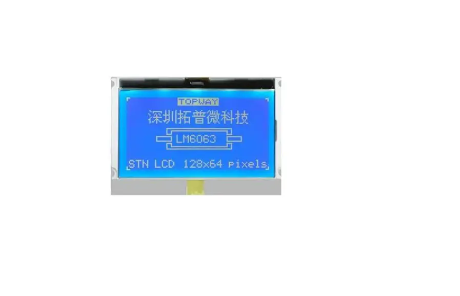
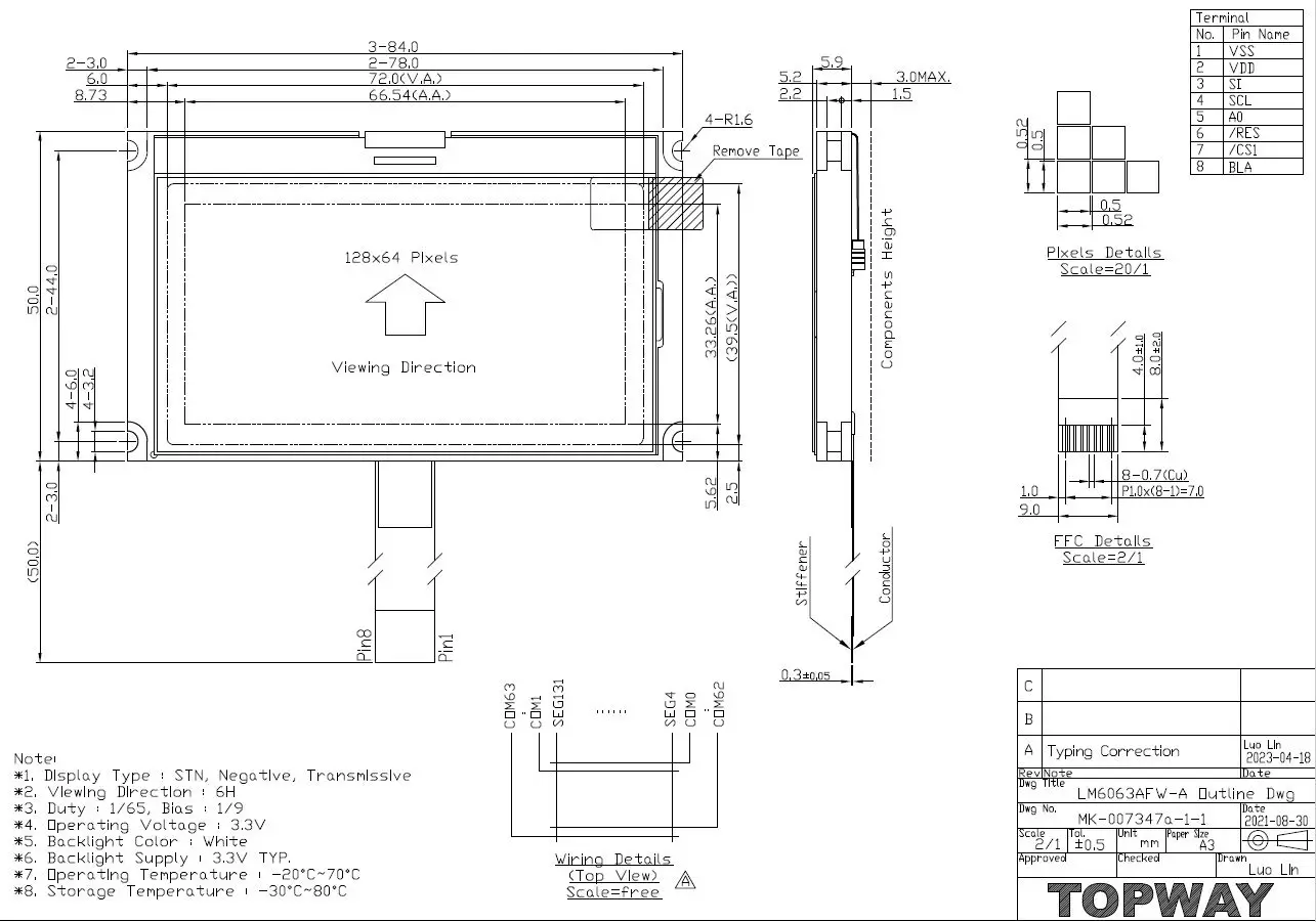
The LM6063AFW-A is an LCD module manufactured by Topway. It features an STN-BLUE, negative, transmissive LCD display mode with a viewing angle of 6H. The display data of 1 is represented by light gray, while the display data of 0 is represented by dark blue. The module has a 1/65 duty and 1/9 bias driving method and uses a white LED backlight. The module has an outline dimension of 84.0 x 50.0 x 8.7 mm. It has a backlit circuit and uses the ST7567A or equivalent as its driver IC. The module has eight pins, each with a specific function, including supply input, input, and control data transfer.
Product Usage Instructions
The LM6063AFW-A is a display module that can be used in various applications, including industrial equipment, medical devices, and consumer electronics. To use the module, connect the module to a power supply and input device using the pins specified in the Terminal Functions section of the user manual. Ensure that the supply voltage does not exceed the maximum limit of +4.0V and that the operating temperature is within the -20°C to +70°C range. If the device is exposed to conditions beyond these limits, it may affect its reliability. When transferring data to the module, ensure that the A0 pin is set to H when transferring display data and L when transferring control data. To initialize the module, set the /RES pin to L, and to disable access to the module, set /CS1 pin to H.It is important to note that any stresses exceeding the Absolute Maximum Ratings specified in the user manual may cause substantial damage to the device. Therefore, ensure that the module is operated within the specified conditions to avoid damage and ensure its longevity.
| Prepared by:
Caiwei
Date: 2023-05-18 | Checked by:
Date: | Approved by:
Date: |
| Rev. | Descriptions | Release Date |
| 0.1 | Preliminary release | 2021-10-15 |
| 0.2 | Update Outine Dwg | 2023-05-18 |
Basic Specifications
Display Specifications
- LCD Display Mode: STN-BLUE, Negative, Transmissive
- Display Color : Display Data = “1” : Light Gray(*1) : Display Data = “0” : Dark Blue (*2)
- Viewing Angle: 6H
- Driving Method : 1/65 duty, 1/9 bias
- Backlight: White LED backlight
Note:
- Color tone may slightly change by Temperature and Driving Conditions.
- The Color is defined as the inactive / background color
Mechanical Specifications
- Outline Dimension: 84.0 x 50.0 x 8.7MAX (mm) (See attached Outline Drawing for details)
Block Diagram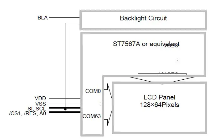
Terminal Functions
| Pin No. | PIN Name | I/O | Descriptions |
| 1 | VSS | Supply | Negative power supply,0V |
| 2 | VDD | Supply | Positive power supply |
| 3 | SI | Input | Serial data input |
| 4 | SCL | Input | Serial clock input |
| 5 | A0 | Input | Register Select A0 = H, Transferring the Display Data A0 = L, Transferring the Control Data |
| 6 | /RES | Input | Reset signal /RES = L, Initialization is executed /RES = H, Normal running. |
| 7 | /CS1 | Input | Chip Select /CS1=L, enable access to the LCD module /CS1=H, disable access to the LCD module |
| 8 | BLA | Supply | Positive power for LED backlight |
Absolute Maximum Ratings
| Items | Symbol | Min. | Max. | Unit | Condition |
| Supply Voltage | VDD | -0.3 | +4.0 | V | VSS = 0V |
| Input Voltage | VIN | -0.3 | VDD+0.3 | V | VSS = 0V |
| Operating Temperature | TOP | -20 | +70 | °C | No Condensation |
| Storage Temperature | TEST | -30 | +80 | °C | No Condensation |
- Cautions: Any Stresses exceeding the Absolute Maximum Ratings may cause substantial damage to the device. Functional operation of this device at other conditions beyond those listed in the specification is not implied and prolonged exposure to extreme conditions may affect device reliability.
Electrical Characteristics
DC Characteristics
| Items | Symbol | MIN. | TYP. | MAX. | Unit | Condition / Application Pin |
| Operating Voltage | VDD | 3.0 | 3.3 | 3.6 | V | VDD |
| Input High Voltage | VIH | 0.7xVDD | – | VDD | V | /RES, /CS1, A0, SI, SCL |
| Input Low Voltage | VIL | VSS | – | 0.3xVDD | V | |
| Operating Current | IDD | – | 0.3 | 1.3 | mA | VDD |
LED Backlight Circuit Characteristics
| Items | Symbol | MIN. | TYP. | MAX. | Unit | Applicable Pin |
| Forward Voltage | VfBLA | – | 3.3 | – | V | BLA |
| Forward Current | IfBLA | – | 85 | 100 | mA | BLA |
Cautions: Exceeding the recommended driving current could cause substantial damage to the backlight and shorten its lifetime.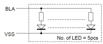
AC Characteristics
Serial Mode Interface
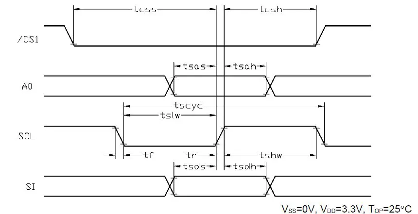
| Item | Symbol | MIN. | TYP. | MAX. | Unit |
| Serial Clock Period | tscyc | 65 | – | – | ns |
| Address setup time (A0) | tsas | 26 | – | – | ns |
| Address hold time (A0) | tsah | 13 | – | – | ns |
| SCL “H” pulse width | tshw | 33 | – | – | ns |
| SCL “L” pulse width | tslw | 33 | – | – | ns |
| Data setup time | tsds | 26 | – | – | ns |
| Data hold time | tsdh | 13 | – | – | ns |
| CS-SCL time | toss | 26 | – | – | ns |
| CS-SCL time | tcsh | 52 | – | – | ns |
Note:
- Input signal rise/fall time should be less than 15ns.
- CL=100pF
- All timing is using 20% and 80% of VDD as the reference.
Reset Timing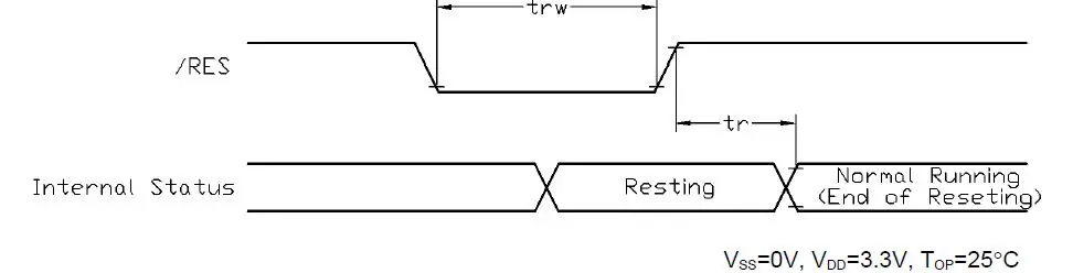
| Item | Symbol | MIN. | TYP. | MAX. | Unit |
| Reset time | tr | – | – | 2.5 | μs |
| Reset LOW pulse width | trw | 2.5 | – | – | μs |
Note: 1.All timing is using 20% and 80% of VDD as the reference.
Function specifications
The Serial Interface
When the serial interface has been selected then when the chip is in active state the serial data input(SI) and the serial clock(SCL) can be received. The serial data is read from the serial data input pin in the rising edge of the serial clock . When “A0”=“H”, the data is display data, and when “A0”=“L”, the data is command.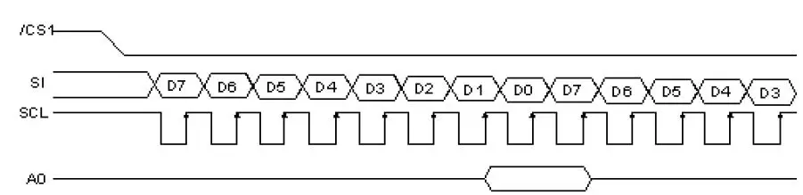 Basic Setting
To drive the LCD module correctly and provide normally display, please use the following setting
- MX = 1 (reverse)
- MY = 0 (normal)
- LCD Bias Select = 1/9
- Initial Display Line = 0
- Entire Display ON/OFF = OFF (normal)
- Reverse Display ON/OFF = OFF (normal)
- Set Power Control Set:
- voltage follower = ON, voltage converter = ON, voltage regulator = ON
- Display ON/OFF = ON
Note:
- These settings/commands should issue the LCD module while starting up.
- See the Display Commands section for details.
Resetting the LCD module
The LCD module should be initialized by using /RES terminal. While turning on the VDD and VSS power supply, maintain /RES terminal at LOW level. After the power supply stabilized, release the reset terminal (/RES=HIGH)
Display Memory Map
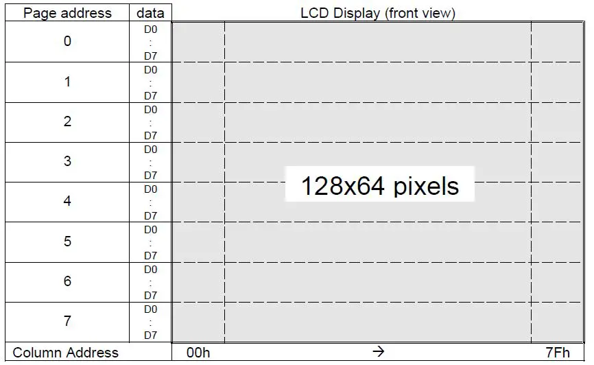
Note:
- MX = 1 (reverse)
- MY = 0 (normal)
- Initial Display Line = 0 URL:
Display Commands
| INSTRUCTION | A0 | /RD | /WR | COMMAND BYTE |
DESCRIPTION | |||||||
| D7 | D6 | D5 | D4 | D3 | D2 | D1 | D0 | |||||
| (1) Display ON/OFF | 0 | 1 | 0 | 1 | 0 | 1 | 0 | 1 | 1 | 1 | D | D=1, display ON D=0, display OFF |
| (2) Set Start Line | 0 | 1 | 0 | 0 | 1 | S5 | S4 | S3 | S2 | S1 | S0 | Set display start line |
| (3) Set Page Address | 0 | 1 | 0 | 1 | 0 | 1 | 1 | Y3 | Y2 | Y1 | Y0 | Set page address |
| (4)Set Column Address | 0 | 1 | 0 | 0 | 0 | 0 | 1 | X7 | X6 | X5 | X4 | Set column address (MSB) |
| 0 | 1 | 0 | 0 | 0 | 0 | 0 | X3 | X2 | X1 | X0 | Set column address (LSB) | |
| (5) Read Status | 0 | 0 | 1 | 0 | MX | D | RST | 0 | 0 | 0 | 0 | Read IC Status |
| (6) Write Data | 1 | 1 | 0 | D7 | D6 | D5 | D4 | D3 | D2 | D1 | D0 | Write display data to RAM |
| (7) Read Data | 1 | 0 | 1 | D7 | D6 | D5 | D4 | D3 | D2 | D1 | D0 | Read display data from RAM |
| (8) SEG Direction | 0 | 1 | 0 | 1 | 0 | 1 | 0 | 0 | 0 | 0 | MX | Set scan direction of SEG MX=1, reverse direction MX=0, normal direction |
| (9) Inverse Display | 0 | 1 | 0 | 1 | 0 | 1 | 0 | 0 | 1 | 1 | INV | INV =1, inverse display INV =0, normal display |
| (10) All Pixel ON | 0 | 1 | 0 | 1 | 0 | 1 | 0 | 0 | 1 | 0 | AP | AP=1, set all pixel ON AP=0, normal display |
| (11) Bias Select | 0 | 1 | 0 | 1 | 0 | 1 | 0 | 0 | 0 | 1 | BS | Select bias setting 0=1/9; 1=1/7 (at 1/65 duty) |
| (12) Read-modify-Write | 0 | 1 | 0 | 1 | 1 | 1 | 0 | 0 | 0 | 0 | 0 | Column address increment: Read:+0 , Write:+1 |
| (13) END | 0 | 1 | 0 | 1 | 1 | 1 | 0 | 1 | 1 | 1 | 0 | Exit Read-modify-Write mode |
| (14) RESET | 0 | 1 | 0 | 1 | 1 | 1 | 0 | 0 | 0 | 1 | 0 | Software reset |
| (15) COM Direction | 0 | 1 | 0 | 1 | 1 | 0 | 0 | MY | – | – | – | Set output direction of COM MY=1, reverse direction MY=0, normal direction |
| (16) Power Control | 0 | 1 | 0 | 0 | 0 | 1 | 0 | 1 | VB | VR | VF | Control built-in power circuit ON/OFF |
| (17) Regulation Ratio | 0 | 1 | 0 | 0 | 0 | 1 | 0 | 0 | RP1 | RP1 | RP0 | Select regulation resistor ratio |
| (18) Set EV | 0 | 1 | 0 | 1 | 0 | 0 | 0 | 0 | 0 | 0 | 1 | Double command!! Set electronic volume (EV) level |
| 0 | 1 | 0 | 0 | 0 | EV5 | EV4 | EV3 | EV2 | EV1 | EV0 | ||
|
(19) Set Booster | 0 | 1 | 0 | 1 | 1 | 1 | 1 | 1 | 0 | 0 | 0 | Double command!! Set booster level: BL=0: 4X BL=1: 5X |
| 0 | 1 | 0 | 0 | 0 | 0 | 0 | 0 | 0 | 0 | BL | ||
| (20) Power Save | 0 | 1 | 0 | Compound Command | Display OFF + All Pixel ON | |||||||
| (21) NOP | 0 | 1 | 0 | 1 | 1 | 1 | 0 | 0 | 0 | 1 | 1 | No operation |
Note:
- Do not use any other command not listed, or the system malfunction may result.
- For the details of the Display Commands, please refer to the ST7567A data sheet.
Power off the LCD Module
It recommends that enter Sleep Mode before powering off the LCD module.
Refreshing The LCD Module
It recommends that the operating modes and display contents be refreshed periodically to prevent the effect of unexpected noise.
Design and Handling Precaution
- The LCD panel is made by glass. Any mechanical shock (eg. dropping form a high place) will damage the LCD module.
- Do not add excessive force on the surface of the display, which may cause the Display color change abnormally.
- The polarizer on the LCD is easily get scratched. If possible, do not remove the LCD protective film until the last step of installation.
- Never attempt to disassemble or rework the LCD module.
- Only Clean the LCD with Isopropyl Alcohol or Ethyl Alcohol. Other solvents (eg. water) may damage the LCD.
- When mounting the LCD module, make sure that it is free from twisting, warping and distortion.
- Ensure to provide enough space (with cushion) between the case and LCD panel to prevent external force adding on it, or it may cause damage to the LCD or degrade the display result.
- Only hold the LCD module by its side. Never hold the LCD module by add force on the heat seal or TAB.
- Never add force to a component of the LCD module. It may cause invisible damage or degrade of reliability.
- LCD modules could be easily damaged by static electricity. Be careful to maintain an optimum anti-static work environment to protect the LCD module.
- When peeling off the protective film from LCD, static charge may cause an abnormal display pattern. It is normal and will resume to normal in a short while.
- Take care and prevent get hurt by the LCD panel sharp edge.
- Never operate the LCD module exceed the absolute maximum ratings.
- Keep the signal line as short as possible to prevent noisy signal from applying to LCD module.
- Never apply signal to the LCD module without power supply.
- IC chip (eg. TAB or COG) is sensitive to the light. Strong lighting environment could possibly cause malfunction. Light sealing structure casing is recommend.
- LCD module reliability may be reduced by temperature shock.
- When storing the LCD module, avoid exposure to the direct sunlight, high humidity, high temperature or low temperature. They may damage or degrade the LCD module

Document Name: LM6063AFW-A-Manual-Rev0.2.DOC
URL: www.topwaydisplay.com.


