


WELCOME
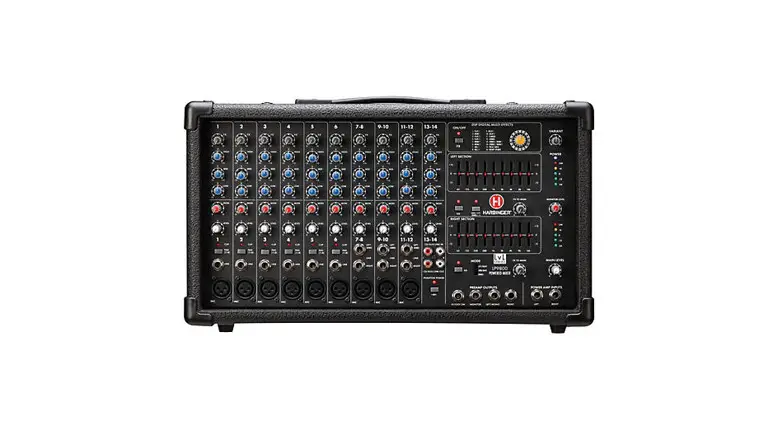
Thank you for your purchase of this Harbinger® Powered Mixer. It’s packed with quality features usually found only on larger, more expensive systems. To get the most from your new LP7800, take a moment and read through this entire manual to learn about all its important features.
Your new PA includes:
- 800W output power with Stereo, Main/Monitor, or Bridge Mono operation
- 7 XLR inputs with 48v Phantom power
- 4 XLR mic/line channels with -25 dB pad and clip indicator
- 3 XLR mic/stereo line channels
- Built-in effects with 24-bit DSP processor with 16 presets
- Two 9-band Graphic Equalizers
- 3-band EQ per channel
- Level control and bi-color Signal/Peak LED on 4 channels
- Stereo Output for recording, Stereo Input for CD/MP3 playback
- Monitor Send per channel
IMPORTANT SAFETY INSTRUCTIONS
DANGER
Exposure to extremely high noise levels may cause permanent hearing loss. Individuals vary considerably to noise-induced hearing loss but most will lose some hearing if exposed to intense noise for a sufficient period of time.
The U.S. Government’s Occupational Safety and Health Administration (OSHA) has specified the following permissible noise level exposures:
| DURATION PER DAY (HOURS) | 8 6 4 3 2 1 |
| SOUND LEVEL (dB) | 90 93 95 97 100 103 |
According to OSHA, any exposure to the above permissible limits could result in some hearing loss. Earplugs or protectors in the ear canal or over the ears must be worn when operating this amplification system in order to prevent permanent hearing loss. If exposure in excess of the limits as put forth above, to ensure against potentially harmful exposure to high sound pressure levels, it is recommended that all persons exposed to equipment capable of inducing high sound pressure levels, such as this amplification the system, be protected by hearing protectors while this unit is in operation.

CAUTION: To reduce the risk of electric shock, do not remove the chassis. No user-serviceable parts inside.
Refer servicing to qualified service personnel.
![]()
THIS SYMBOL IS INTENDED TO ALERT THE USER TO THE PRESENCE OF NON-INSULATED “DANGEROUS VOLTAGE” WITHIN THE PRODUCT’S ENCLOSURE THAT MAY BE OF SUFFICIENT MAGNITUDE TO CONSTITUTE A RISK OF ELECTRIC SHOCK TO PERSONS.![]()
THIS SYMBOL IS INTENDED TO ALERT THE USER TO THE PRESENCE OF IMPORTANT OPERATING AND MAINTENANCE (SERVICING) INSTRUCTIONS IN THE LITERATURE ACCOMPANYING THE UNIT.![]()
APPARATUS SHALL NOT BE EXPOSED TO DRIPPING OR SPLASHING AND THAT NO OBJECTS FILLED WITH LIQUIDS, SUCH AS VASES, SHALL BE PLACED ON THE APPARATUS.
IMPORTANT SAFETY INSTRUCTIONS
- Read all safety and operating instructions before using this product.
- All safety and operating instructions should be kept for future reference.
- Read and understand all warnings listed on the operating instructions.
- Follow all operating instructions to operate this product.
- This product should not be used near water, i.e. a bathtub, sink, swimming pool, wet basement, etc.
- Use only a dry cloth to clean this product.
- Do not block any ventilation openings. The product should not be placed flat against a wall or placed in a built-in enclosure that will impede the flow of cooling air.
- Do not install this product near any heat sources, such as radiators, heat registers, stoves or any other apparatus (including heat-producing amplifiers) that produces heat.
- Do not defeat the safety purpose of the polarized or grounding-type plug. A polarized plug has two blades with one wider than the other. A grounding-type plug has two blades and a third grounding prong. The wide blade or the third prong is provided for your safety. If the provided plug does not fit into your outlet, consult an electrician for the replacement of the obsolete outlet.
- Protect the power cord being walked on or pinched, particularly at plugs, convenience receptacles, and the point where they exit from the apparatus. Do not break the ground pin of the power supply cord.
- When a cart is used, use caution when moving the cart/apparatus combination to avoid injury from tip-over.

- Unplug this apparatus during lightning storms or when unused for long periods of time.
- Care should be taken so that objects do not fall and liquids are not spilled into the unit through the ventilation ports or any other openings.
- Refer all servicing to a qualified service professional. Servicing is required when the apparatus does not operate normally or has been damaged in any way, including damage to the power cord or plug, damage due to liquids spilled or objects dropped inside the unit, dropping the unit, or anything else that interrupts normal use of the unit.
- WARNING: To reduce the risk of fire or electric shock, do not expose this apparatus to rain or moisture.
- Protective Ground Terminal. The apparatus shall be connected to an AC main socket with a protective earth-ground connection.
BASIC OPERATION
- Ensure the LP7800’s AC power switch is turned off.
- Place the LP7800 on the floor, a table, or a sturdy stand.
- Turn down all Level, Monitor Level, and Main Level Controls.
- Plug speakers into the rear panel speaker jacks.
NOTE: Speakers should be placed in a location that allows for unobstructed (line-of-sight) sound projection to the audience. In many venues, it is beneficial to place speakers on speaker stands for best results. - Plug sources such as microphones, instruments, or CD/MP3 players into the front panel jacks.
- Turn AC Power switch to “On”.
- Slowly turn the Main Level to 12 o’clock.
- Slowly turn the Level control on each input Channel up to the desired volume level.
FRONT AND REAR PANEL DIAGRAMS
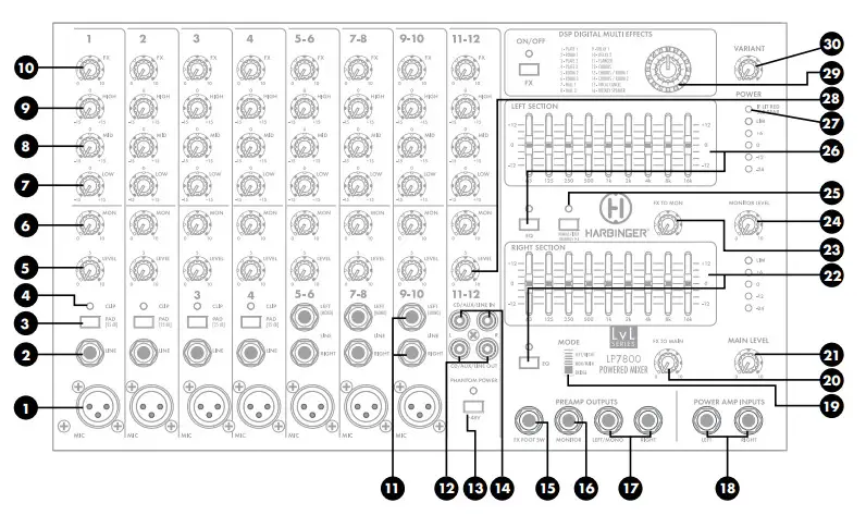
FRONT PANEL


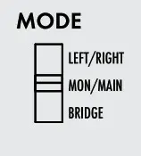
Note: The Mode switch is recessed to help avoid accidental changes when the amplifier is being used. To change modes, turn off the amp and use a flat-wedged screwdriver to change the assignment.
MAIN L – MAIN R
- Stereo Mode
- Output 1 is Left signal
- Output 2 is the Right signal
- Monitor outputs to Monitor Out jack only
- 4Ω minimum speaker load per output
MAIN L+R – MONITOR
- Dual Mono Mode
- Output 1 is Main
- Output 2 is Monitor
- 4Ω minimum speaker load per output
Bridge – Bridge
- Amplifiers 1 and 2 combines into a single, larger amplifier (Mono)
- Bridge Output is typically used for the subwoofer, with Main and Monitor Line Outputs connected to powered speakers
- 8Ω minimum speaker load
| 20. | FX to Main Level This control sends a signal from the FX/Aux return to the Main speakers and Main Line Output. |  |
| 21. | Main Level This knob controls the overall output level delivered to the speakers. |  |
| 22. | Monitor & Main 9-Band Graphic EQ Graphic Equalizer contains 9 filters that each cut or boost +/- 12dB around their center frequency. These filters can be used to contour the overall sound of all inputs and reduce feedback (cut only). LED per EQ band. Press EQ button to engage Equalizer | 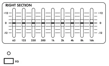 |
| 23. | FX to Mon Level This control sends a signal from the FX/Aux return. |  |
| 24. | Monitor Level This knob controls the output level of the Monitor Out jack. Each input Level control feeds both the Main Out (power amp) and Monitor Line Out. |  |
| 25. | Rumble Filter This switch engages a low-cut filter on channels 1–4 to reduce unwanted low-frequency rumble vibration in the mic stand or cable. |  |
| 26. | Main 9-Band Graphic EQ Graphic Equalizer contains 9 filters that each cut or boost +/- 12dB around their center frequency. These filters can be used to contour the overall sound of all inputs and reduce feedback (cut only). LED per EQ Band. Press EQ bottom to engage Equalizer | 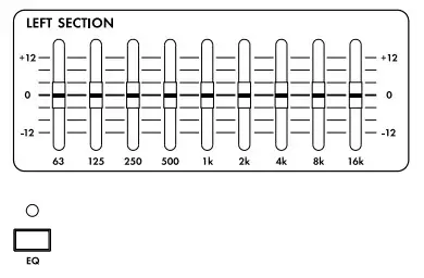 |
| 27. | Power/Protection LED This LED is lit blue when the unit is powered on and functioning normally. If lit red, the built-in protection circuit has activated. Please consult the rear of unit for troubleshooting tips and avoid incompatible speaker load, blocked vents, lack of airflow, or extreme heat. |  |
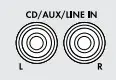
| 28. | Stereo-In Level This is the volume level for any devices connected to the CD/AUX inputs. The sound from CD/MP3 IN goes directly to the MAIN Output. |  |
| 29. | DSP Program This knob is used to select the 16 preset FX programs from the built-in 24-bit DSP FX processer. Turn the knob to the desired FX preset. | 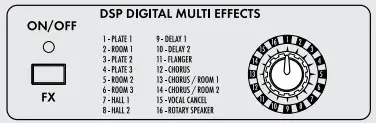 |
| DSP 24-BIT FX PRESET TABLE | ||
| NO. | PRESET | PARAMETER |
| 1 | Plate 1 | Reverb Delay Time: 50ms |
| 2 | Room 1 | Decay Time: 50ms |
| 3 | Plate 2 | Reverb Delay Time: 50ms |
| 4 | Plate 3 | Reverb Delay Time: 80ms |
| 5 | Room 2 | Decay Time: 50ms |
| 6 | Room 3 | Decay Time: 80ms |
| 7 | Hall 1 | Decay Time: 50ms |
| 8 | Hall 2 | Decay Time: 80ms |
| 9 | Delay 1 | Delay Time: 100mS |
| 10 | Delay 2 | Delay Time: 300mS |
| 11 | Flanger | Decay Time: 50mS |
| 12 | Chorus | Rate: 44.1K |
| 13 | Chorus/Room1 | Rate: 22K |
| 14 | Chorus/Room2 | |
| 15 | Vocal Cancel | Modulation Depth: 6dB |
| 30. | Variant Knob This knob changes the character of the effect depending on the effect type. It either changes the length of reverb, the feedback/repeat amount of a delay, or the depth of a modulation effect. See the preset descriptions above for more information on how this control works. |  |
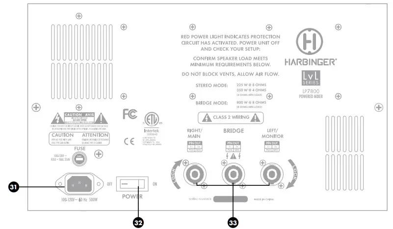
| 31. | AC Power Cord Input This is the AC Mains connection. Use only the supplied IEC cable or a UL listed replacement IEC Cable and 100-120V/60Hz switching power supply. | 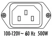 |
| 32. | On-Off Switch This switch turns on the LP7800 and off. When powered on the blue power led will light. |  |
| 33. | Speaker Outputs L/Monitor Connect up to two (2) loudspeakers to the speaker output jacks. Note that the LP7800 power amp is rated at 4Ω Minimum Load. You may safely connect 2 x 8Ω speakers or 1 x 4Ω speaker. | 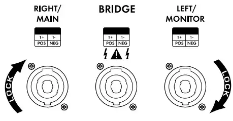 |
Bridge Output (Mono) Connect one (1) 8Ω speaker to this output.
Note that damage may occur to the LP7800 if using Bridge Mode with more than one 8Ω speaker.
R/Main Connect up to two (2) loudspeakers to the speaker output jacks. Note that the LP7800 power amp is rated at 4Ω Minimum Load. You may safely connect 2 x 8Ω speakers or 1 x 4Ω speakers.
Note: Twist-lock outputs are configured 1+ (pos)/1- (neg). If Bridge Mono is used, no speakers should be connected to Right/Main or Left Monitor
SPECIFICATIONS
| Power Amplifier (Output): | ||
| Input Channels | Microphone Inputs Frequency Response Gain Line Inputs Frequency Response Gain | -60dBu 20Hz-20KHz(±1dB) 36dB -50dBu 20Hz-20KHz(±0.5dB) 24dB |
| Impedance | Microphone Input All Other Inputs Tape Out All Other Outputs | 2.2KΩ balanced/ 1.1KΩ unbalanced 47KΩ unbalanced 120Ω 100Ω |
| Equalization | High Shelving Mid Shelving Low Shelving Graphic EQ | 10KHz ±15dB 2KHz ±15dB 60Hz ±15dB 65Hz/125Hz/250Hz/500Hz/1KHz /2KHz/4KHz/8KHz/16KHz (±12dB) |
| DSP section | A/D and D/A Converters DSP Resolution Type of Effects Presets Controls | YES 24BIT AL3201 YES encoder |
| Main Mix Section | Noise (Bus noise) Monitor Max Out FX Sends Max Out Total Harmonic Distortion Signal to Noise Ratio Static Power Consumption Power Source | ≤0.5mV +21dBu +21dBu 1% 90dB 50W 115V-50/60Hz |
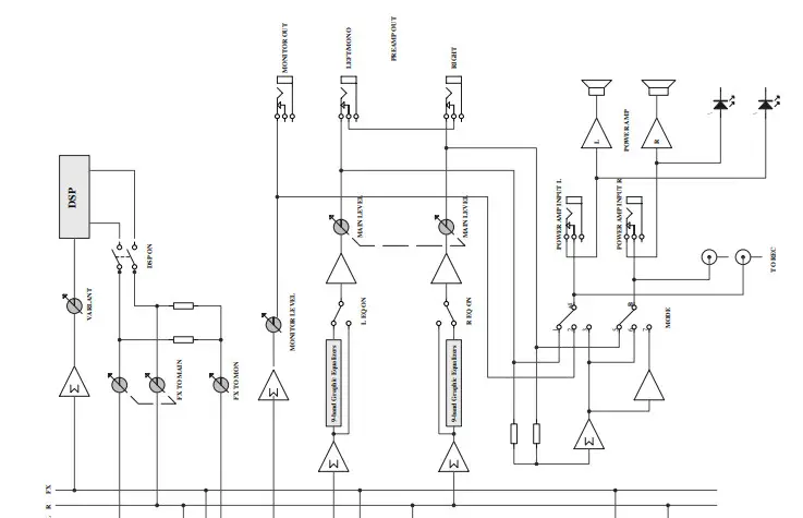
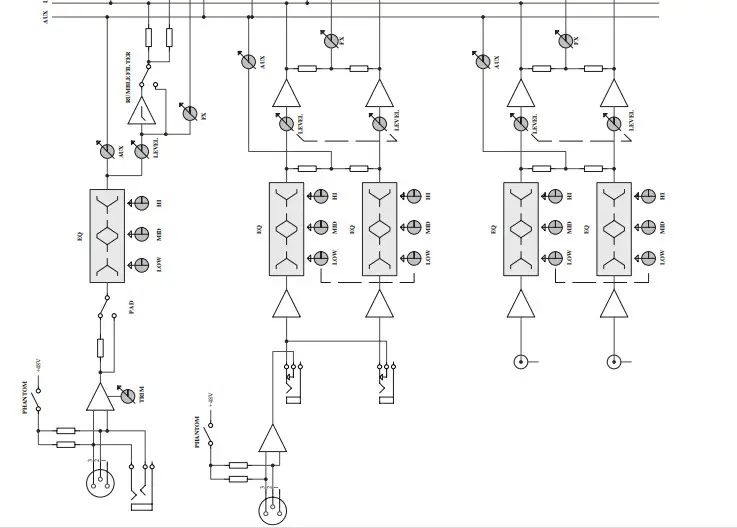
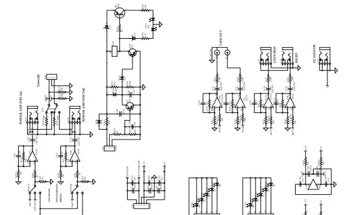
SIGNAL FLOW DIAGRAM

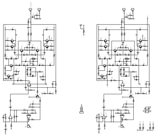
POWER AMPLIFIER DIAGRAM
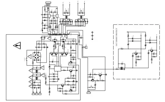
OUTPUT BLOCK DIAGRAM
WARRANTY
Have a question about service, warranty or parts?
Call 888-286-1809 (Toll-Free)
So we may serve you better, please register online at www.HarbingerProAudio.com
2 YEAR HARBINGER LIMITED WARRANTY
Harbinger provides, to the original purchaser, a two (2) year limited warranty on materials and workmanship on all Harbinger cabinets, loudspeaker, and amplifier components from the date of purchase.
For warranty support, please visit our website at www.HarbingerProAudio.com, or contact our Support Team at 888-286-1809 for assistance. Harbinger will repair or replace the unit at Harbinger’s discretion.
This warranty does not cover service or parts to repair damage caused by neglect, abuse, normal wear, and tear and cosmetic appearance to the cabinetry not directly attributed to defects in materials or workmanship. Also excluded from coverage are damages caused directly or indirectly due to any service, repair(s), or modifications of the cabinet, which has not been authorized or approved by Harbinger. This two (2) year warranty does not cover service or parts to repair damage caused by accident, disaster, misuse, abuse, burnt voice coils, over-powering, negligence, inadequate packing, or inadequate shipping procedures.
The sole and exclusive remedy of the foregoing limited warranty shall be limited to the repair or replacement of any defective or non-conforming component. All warranties including, but not limited to, the express
FCC STATEMENTS
- Caution: Changes or modifications to this unit not expressly approved by the party responsible for compliance could void the user’s authority to operate the equipment.
- Note: This equipment has been tested and found to comply with the limits for a Class B digital device, pursuant to Part 15 of the FCC Rules. These limits are designed to provide reasonable protection against harmful interference in a residential installation. This equipment generates, uses, and can radiate radio frequency energy and, if not installed and used in accordance with the instructions, may cause harmful interference to radio communications. However, there is no guarantee that interference will not occur in a particular installation. If this warranty and the implied warranties of merchantability and fitness for a
particular purpose are limited to the two (2) year warranty period. Some states do not allow limitations on how long an implied warranty lasts, so the above limitation may not apply to you. There are no express warranties beyond those stated here. In the event that applicable law does not allow the limitation of the duration of the implied warranties to the warranty period, then the duration of the implied warranties shall be limited to as long as is provided by applicable law. No warranties apply after that period.
Retailer and manufacturer shall not be liable for damages based upon inconvenience, loss of use of the product, loss of time, interrupted operation or commercial loss or any other incidental or consequential damages including but not limited to lost profits, downtime, goodwill, damage to or replacement of equipment and property, and any costs of recovering, reprogramming, or reproducing any program or data stored in equipment that is used with Harbinger products. This guarantee gives you specific legal rights; you may have other legal rights, which vary from state to state.
Harbinger P.O. Box 5111, Thousand Oaks, CA 91359-5111
All trademarks and registered trademarks mentioned herein are recognized as the property of their respective holders.
Equipment does cause harmful interference to radio or television reception, which can be determined by turning the equipment off and on, the user is encouraged to try to correct the interference by one or more of the following measures:
•Reorient or relocate the receiving antenna
• Increase the separation between the equipment and receiver
• Connect the equipment into an outlet on a circuit different from that to which the receiver is connected
•Consult the dealer or an experienced radio/TV technician for help