ELTEC CYBOX AP-A Wireless Access Point with Integrated Antenna
DISCLAIMER
Copyright
© 2022 ELTEC Elektronik AG. The information, data, and figures in this document including respective references have been verified and found to be legitimate. In particular in the event of error they may, therefore, be changed at any time without prior notice. The complete risk inherent in the utilization of this document or in the results of its utilization shall be with the user; to this end, ELTEC Elektronik AG shall not accept any liability. Regardless of the applicability of respective copyrights, no portion of this document shall be copied, forwarded or stored in a data reception system or entered into such systems without the express prior written consent of ELTEC Elektronik AG, regardless of how such acts are performed and what system is used (electronic, mechanic, photocopying, recording, etc.). All product and company names are registered trademarks of the respective companies.
Our General Business, Delivery, Offer, and Payment Terms and Conditions shall otherwise apply.
SAFETY INFORMATION
Electrical safety
![]() WARNING
WARNING
The device can be operated with voltages up to 56 V DC. Incorrect handling risks causing a fatal electrical shock.
General advice
- Only qualified personnel is allowed to install, operate and maintain the devices.
- Please take safety precautions against electrostatic discharge (ESD).
- To prevent the risk of electric shock, turn off the external power supply and remove the power supply cable from the electrical outlet before handling or disassembling the system.
- When adding or removing devices to or from the system, ensure that the power cables for the devices are unplugged before the signal cables are connected.
- Make sure that your power supply is set to the correct voltage in your area. If you are not sure about the voltage of the electrical outlet you are using, contact your local power company.
- If the power supply is broken, do not try to fix it by yourself. Contact a qualified service technician or your retailer.
Operation safety
![]() WARNING
WARNING
The device can become hot during operation (~ 60 ° C). Make sure it is protected from accidental contact. The device must be installed so that it is not accessible to children.
To prevent burns, switch off the device and allow to cool down for half an hour before disassembling or working on it.
- Before installing the device and connecting cables to it, carefully read the related manuals.
- Before using the device, make sure all cables are correctly connected and the power cables are not damaged. If you detect any damage, contact your dealer immediately.
- Connect cables and use cable holder to avoid any tension forces on the connectors.
- Avoid dust, humidity, and temperature extremes. Do not place the product in any area where it may become wet.
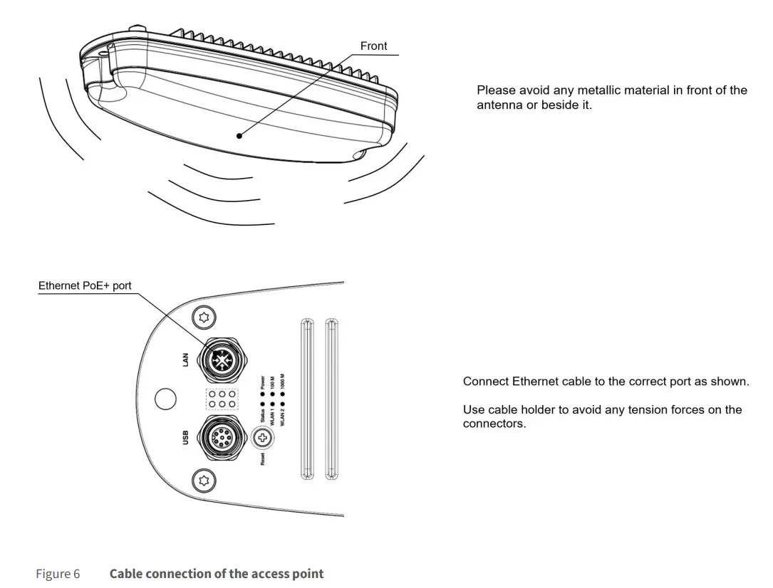
- Please avoid any metallic material in front of the antenna or beside it.
- Place the product on a stable surface.
- If you encounter technical problems with the product, contact a qualified service technician or your retailer.
Radio Frequency Exposure Statement
At least 20 cm separation distance between the antenna and the user’s body must be maintained at all times.
RECYCLING
Please recycle packaging environmentally friendly:
![]() Packaging materials are recyclable. Please do not dispose packaging into domestic waste but recycle it.
Packaging materials are recyclable. Please do not dispose packaging into domestic waste but recycle it.
Please recycle old or redundant devices environmentally friendly:
![]() Old devices contain valuable recyclable materials that should be reutilized. Therefore, please dispose old devices at collection points which are suitable.
Old devices contain valuable recyclable materials that should be reutilized. Therefore, please dispose old devices at collection points which are suitable.
EU DECLARATION OF CONFORMITY
![]() ELTEC Elektronik AG herewith declares that the device is compliant to the basic requirements of the directive 2014/53/EU. The full text of the EU declaration of conformity is available in the Download Center at www.eltec.com.
ELTEC Elektronik AG herewith declares that the device is compliant to the basic requirements of the directive 2014/53/EU. The full text of the EU declaration of conformity is available in the Download Center at www.eltec.com.
UNITED STATES – FCC
This device complies with FCC Rules Part 15. Operation is subject to the following two conditions:
- this device may not cause harmful interference and
- this device must accept any interference received including interference that may cause undesired operation.
This equipment has been tested and found to comply with the limits for a Class A digital device, pursuant to part 15 of the FCC Rules. These limits are designed to provide reasonable protection against harmful interference when the equipment is operated in a commercial environment. This equipment generates, uses, and can radiate radio frequency energy and, if not installed and used in accordance with the instruction manual, may cause harmful interference to radio communications. Operation of this equipment in a residential area is likely to cause harmful interference in which case the user will be required to correct the interference at his own expense.
CANADA – ISED
This device complies with Industry Canada’s license-exempt RSSs. Operation is subject to the following two conditions:
- this device may not cause interference and
- this device must accept any interference, including interference that may cause undesired operation.
This equipment has been tested and found to comply with the limits for a Class A digital device, pursuant to the Interference-Causing Equipment Standard ICES-003.
CONTACT
ELTEC Elektronik AG
Galileo-Galilei-Straße 11
55129 Mainz
Germany
Fon +49 6131 918 100
Fax +49 6131 918 195
Email [email protected]
www www.eltec.com
ABOUT THIS DOCUMENT
This installation manual is intended only for system developers and integrators; it is not intended for end users.
It describes the hardware functions of the product, connection of peripheral devices and integration into a system. Additional information on special applications and the configuration of the product is available in a separate configuration manual which can be downloaded from the Download Center at www.eltec.com.
OVERVIEW
PRODUCTS
This installation manual comprises all information to set-up the following product.
HARDWARE
DEVICE CONNECTORS
POWER OVER ETHERNET (POE+)
The CyBox AP-A is designed to be supplied via the Ethernet uplink, as class 4 powered device, according to IEEE 802.3at. In this case the supply voltage is provided remotely over the injector.
ETHERNET INTERFACES
The LAN port of the CyBox AP-A is utilizing a M12 X-coded connector (CAT-6A) with the pin assignment as shown in Table 1. Mating connectors are available from several manufacturers.
| PIN | SIGNAL NAME | DESCRIPTION | |
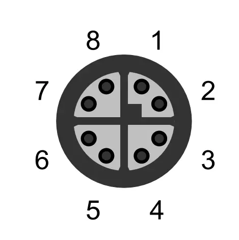 | 1 | D1+ | First data line plus |
| 2 | D1- | First data line minus | |
| 3 | D2+ | Second data line plus | |
| 4 | D2- | Second data line minus | |
| 5 | D4+ | Fourth data line plus | |
| 6 | D4- | Fourth data line minus | |
| 7 | D3- | Third data line minus | |
| 8 | D3+ | Third data line plus |
Table 1 Pin Assignment of M12 Ethernet Connector (LAN 1)
ANTENNAS
The Cybex AP-A consists of a single housing with integrated antennas which are located behind the plastic cover of the device. There is no need for external RF cable installation because each of the two radio modules is connected internally to the antennas via pigtails.
The CyBox AP-A is equipped with a USB and serial port. The USB port can be used to attach a memory device to update the firmware or to configure the device. Note that the USB port is a dedicated maintenance port. It is not designed to be used while the device is in operation inside rolling stock equipment.
Table 2 shows the pin assignment of the power supply connector
| PIN | SIGNAL NAME | DESCRIPTION | |
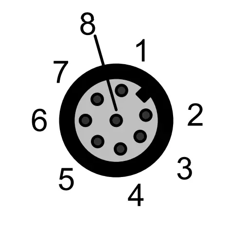 | 1 | USB-VCC | USB positive power supply voltage |
| 2 | USB-D- | USB negative data line | |
| 3 | USB-D+ | USB positive data line | |
| 4 | USB-GND | USB negative power supply voltage | |
| 5 | DNC | Do not connect | |
| 6 | RS232-TX | Console port transmit data | |
| 7 | RS232-RX | Console port receive data | |
| 8 | RS232-GND | Console port ground |
Table 2 Pin Assignment of M12 Service Connector
COVER PLATE WITH INTERFACES
The figure below provides an overview of the cover plate.
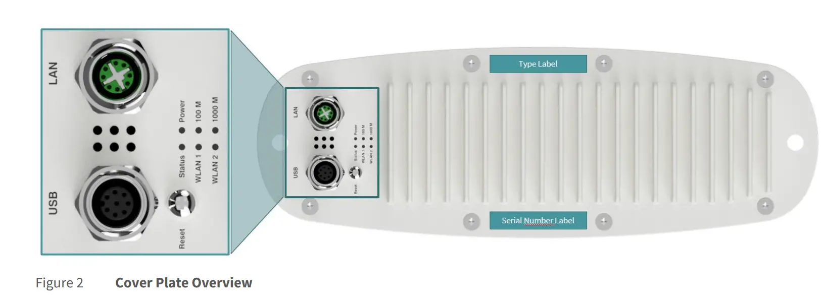
LED INDICATORS
The LEDs on the cover plate of CyBox AP-A provide quick indication of the device status.
POWER LED STATUS
| LED COLOR | STATE | DESCRIPTION |
| Green | On | Device is receiving correct input power |
| Green | Off | Device is not powered |
Table 3 Power LED Status
STATUS LED STATUS
| LED COLOR | STATE | DESCRIPTION |
| Green | On | Normal operation |
| Green | Off | Device is booting | self-testing |
| Green | Blinking | Device is resetting to factory settings |
| Green/Red | Toggle Green/Red | Emergency system booted |
| Red | On | Software | Configuration error |
| Red | Off | Normal operation |
Table 4 Status LED Status
WLAN 1 LED STATUS
| LED COLOR | STATE | DESCRIPTION |
| Green | On | Indicates module 1 is in use |
| Green | Blinking | Indicates data transfer on module 1 |
| Green | Off | Indicates module 1 is inactive |
Table 5 WLAN 1 LED Status
WLAN 2 LED STATUS
| LED COLOR | STATE | DESCRIPTION |
| Green | On | Indicates module 2 is in use |
| Green | Blinking | Indicates data transfer on module 2 |
| Green | Off | Indicates module 2 is inactive |
Table 6 WLAN 2 LED Status
LAN LED (100 M) STATUS
| LED COLOR | STATE | DESCRIPTION |
| Green | On | 100 Mbit/s link established |
| Green | Blinking | Indicates 100 Mbit/s data transfer |
| Green | Off | No 100 Mbit/s link |
Table 7 LAN LED (100 M) Status
LAN LED (1000 M) STATUS
| LED COLOR | STATE | DESCRIPTION |
| Green | On | 1000 Mbit/s link established |
| Green | Blinking | Indicates 1000 Mbit/s data transfer |
| Green | Off | No 1000 Mbit/s link |
Table 8 LAN LED (1000 M) Status
RESET SWITCH
The CyBox AP-A is equipped with a hidden reset switch behind the cover plate, close to the service connector. The button is accessible with a straightened paper clip pushed through the little hole behind the sealing screw on the cover plate. The sealing screw must be tightened with a torque of 1.2 Nm. The effect of pressing the reset switch depends on the duration of its activation, as indicated in Table 9 below. The timing behavior is only valid if the device has completely booted (after approx. 1 min). While the device is booting or executing U-Boot, pushing the button will always reset the device.
The following table describes the functions of the reset switch.
| HOLD TIME | STATUS LED BEHAVIOR | ACTION |
| < 2 seconds | Off | Reset after release |
| 2-5 seconds | Off | No action |
| > 5 seconds | Green blinking | Remove custom configuration then reset |
Table 9 Reset Switch Behavior
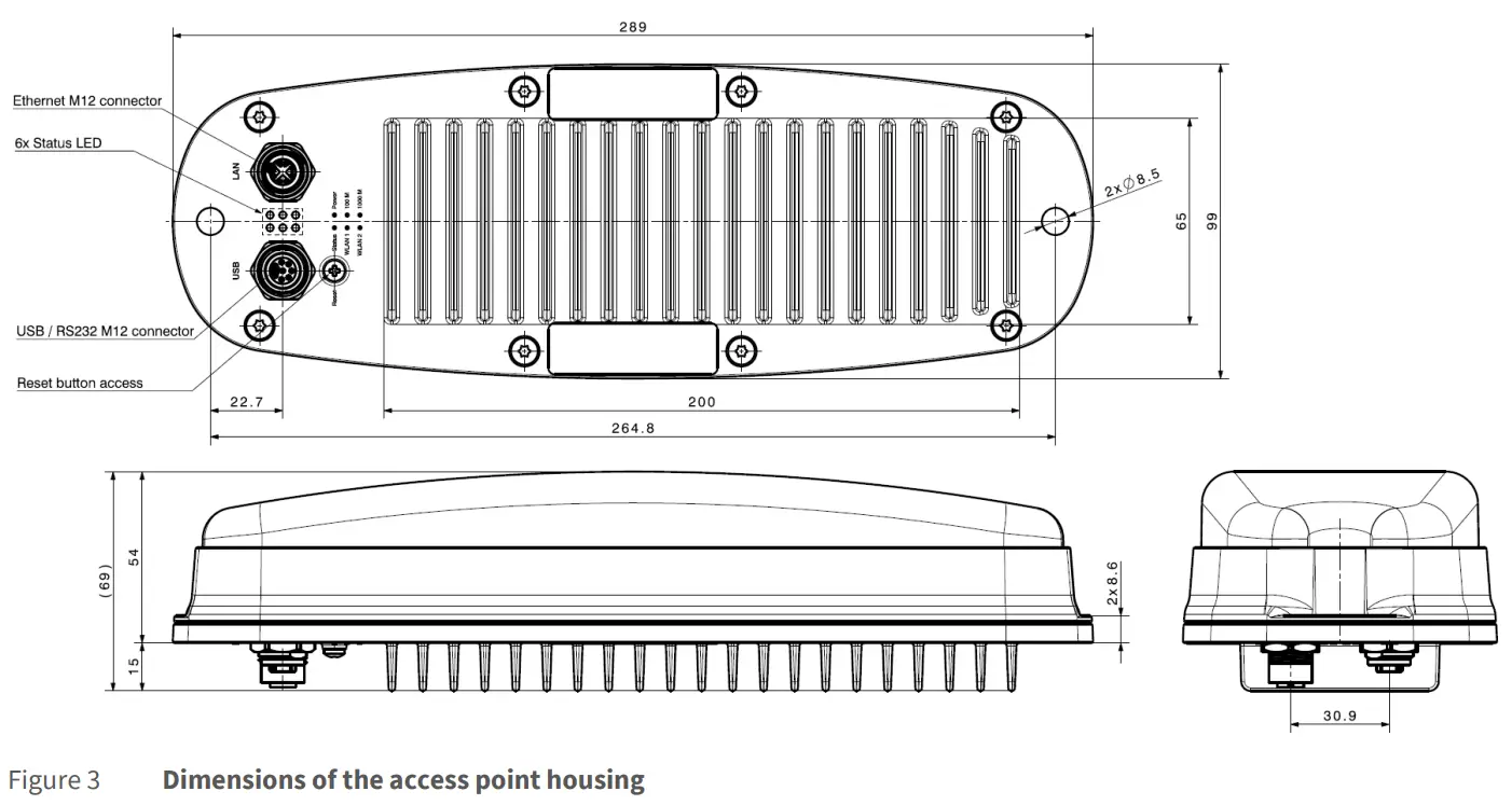
MOUNTING
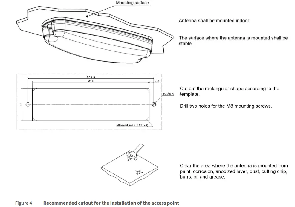
When mounting the CyBox AP-A please consider the following aspects:
- Do not install the device close to any sources of heat such as radiators or heat registers.
- Keep the device away from any liquids. The protection class of the housing is IP54.
- Keep a free space of at least 150 mm around the cooling fins to ensure adequate heat dissipation capabilities.
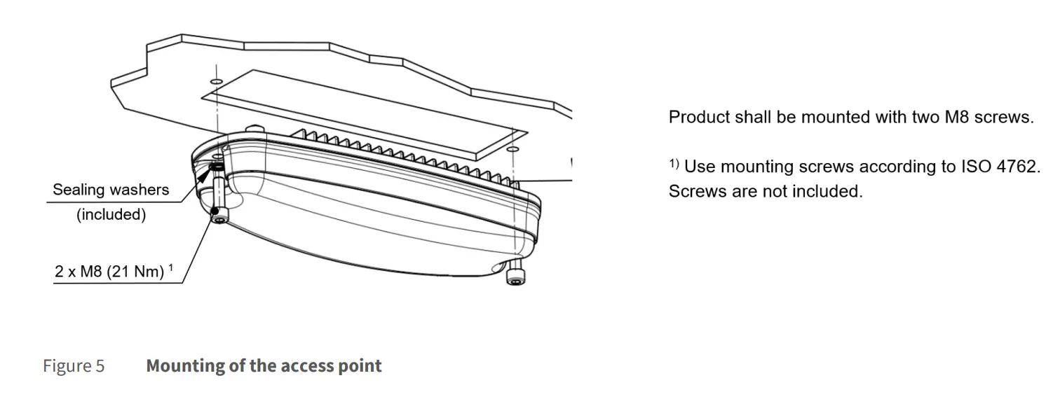
- The housing provides two mounting holes to install the device in horizontal or vertical orientation on a planar, flat and stable surface with a cutout for the connectors and cooling fins.
- For fixation use two M8 screws of sufficient length (ISO 4762) with the included M8 washers.
The drawings in Figure 3 to Figure 5 show the outer dimensions of the housing and installation process for the access point, including the position of the mounting holes.
ELECTRICAL CONNECTION
- Establish a connection to the network by plugging a M12 patch cable to M12 ethernet connector on the cover plate which is shown in Figure 6.
- Make sure to use a PoE+ injector for correct operation.
- Ensure that the ethernet cable is intact and undamaged. Do not switch on the system if there are damages on the ethernet cable or plug.
- Use power cables which are approved for the power supply in your country.
- The device itself has no on/off switch It starts as soon as it is supplied with power.