![]()
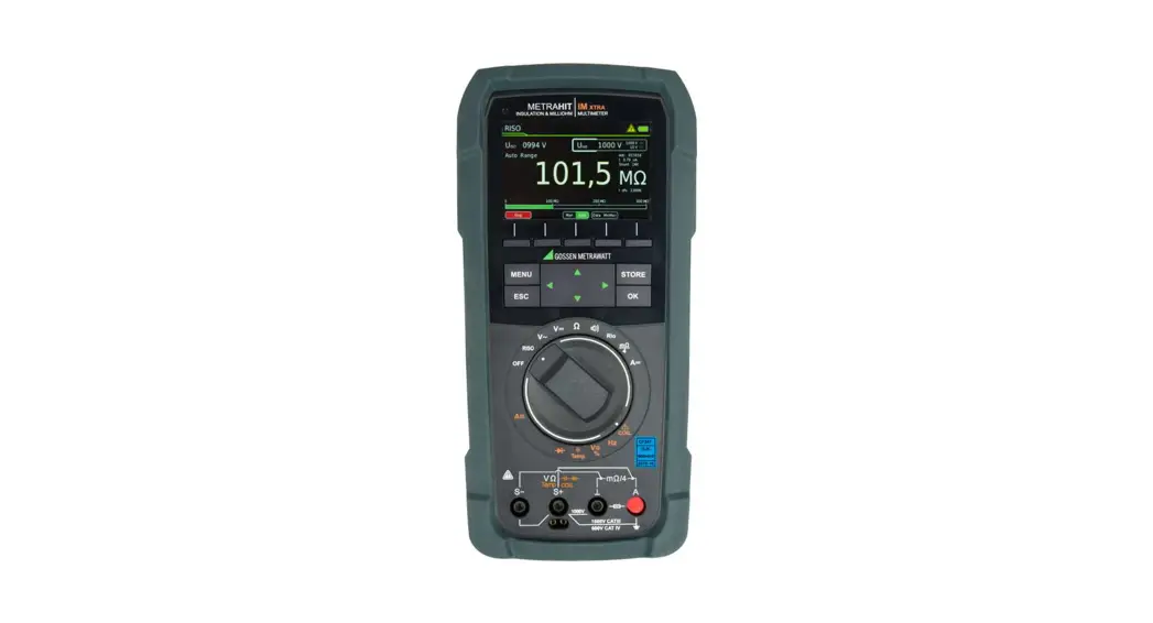
METRAHIT IM XTRA Short-Circuited Coil Tester
User Manual
![]()
![]()
reddot award 2018 winner industrial design
METRAHIT IM XTRA Short-Circuited Coil Tester
- Insulation resistance measurement up to 3.1 GΩ with interference voltage detection, test voltages:50, 100, 250, 500 and 1000 V per DIN EN 61557-2 / VDE 0413-2
- DAR: dielectric absorption rate, PI: polarization index
- 4-wire milliohm measurement (Kelvin connection), 200 mA or 1 A measuring current for precise measurement of extremely small resistances with a resolution of 1 μ
- 2-wire Rlo measurement with 200 mA test current per DIN EN 61557-4 / VDE 0413-4
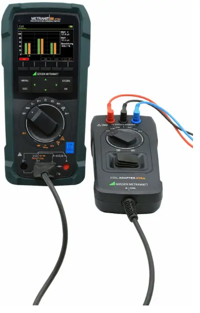
- Short-circuited coil test with 1000 V and optional COIL adapter
- Multifunctional measuring instrument (V, A, Ω, F, Hz, %, RPM, °C/°F)
- TRMS AC / AC+DC measurement for current/voltage value up to 10/100 kHz
- Low-pass filter can be activated, 1 kHz (-3 dB) in the V AC, AC+DC range
- Direct current measurement, 10 nA to 1 A
- Current measurement with clamp sensors – transformation ratio can be adjusted with CLIP from 1:1 to 1:1000 and is taken into account in the amperage display
- Capacitance measurement
- Precision temperature measurement – °C, and °F for RTD and TC-K sensors
- Diode measurement (IK = 1 mA, UFlow up to 5.1 V) and continuity testing
- Acoustic signals
- Acquisition of min./max. values, DATA Hold
- Data logger thanks to integrated memory module and real-time clock, individual measurements as well
- Push/print function transfers measured values to software by pressing a key
- Programmable sequences for test routines
- Color graphic display
- Modular supply power: standard quick-change rechargeable lithium battery, optional WPC module for inductive charging and mains module with USB port, change without interrupting the measuring circuit thanks to touch protected module socket
- Automatic blocking sockets for the current input
- Remote probe with START (ISO) and STORE keys
- Housing with IP52 protection, dust and splash protected, replaceable rubber holster
- Interfaces: Bluetooth or WLAN integrated, USB with optional mains module
- IZYTRONIQ windows software for documentation, preparation of test reports and graphic evaluation of measurements
Applications
The METRAHIT IM XTRA and the METRAHIT IM E-DRIVE are portable, extremely rugged multimeters designed for use in the field. They’re suitable for maintenance, service and diagnosis at electric machines, drive units and systems, for example in automotive, energy and automation applications.
METRAHIT IM XTRA and METRAHIT IM E-DRIVE multimeters are all-inone instruments: insulation tester, milliohmmeter, short-circuited coil tester and universal
multimeter. They’re ideal for safety testing and diagnosis at electric and hybrid vehicles, as wellas all types of electric machines.
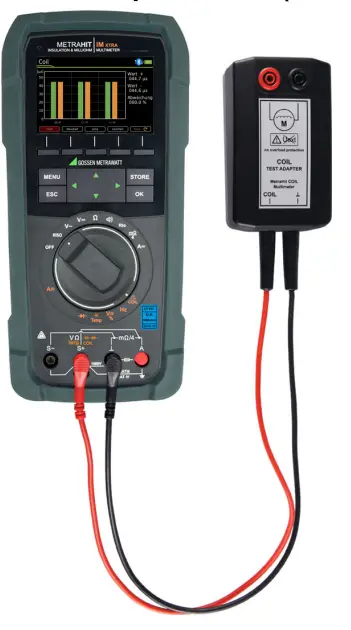
The METRAHIT IM XTRA and the METRAHIT IM E-DRIVE make it possi- ble to test coils for short-circuits within an inductance range of 10 μH to 50 mH (at 100 Hz) in combination with the optional COILAdapter 50mH. This range corresponds to motors in accordance with DIN standards with power ratings of roughly 15 kVA to 80 MVA. A universal adapter for motors with medium power ratings is in preparation.
Features
Insulation Resistance Measurement with Interference Voltage Detection
Insulation resistance measurement with test voltages of 50 to 1000 V. If interference voltage of greater than 15 V AC or 25 V DC is detected during insulation measurement, an error message appears briefly at the display, after which automatic switching to TRMSAC+DC voltage measurement at 1 MΩ takes place.
Polarization Index (PI):
When test voltage is applied, insulation resistance is measured after one minute and after ten minutes. The polarization index is the ratio which results from the two measured values. In the case of electric drive units, a value of at least 2 indicates intact insulation and a value of greater than 4 indicates very good insulation.
Absorption Index (DAR)
Practically speaking, the absorption index test is a quick polarization index measurement. The ISO values measured after 30 and 60 seconds are used to generate a ratio.
METRAHIT IM XTRA & METRAHIT IM E-DRIVE
Isolation Tester, Milliohmmeter, TRMS Multimeter, Short-Circuited Coil Tester
Kelvin Connection for 4-Wire Measurement (4-L) (milliohm measurement)
The 4-wire measurement compensates for influences resulting from cable and contact resistances which must not be neglected when measuring very small resistances. Measuring current can be set to 200 mA or 1 A. In this way, even extremely small contact resistances can be measured, for example at welded and riveted joints and on aircraft outer skins (lightning protection and wick test), or equipotential bonding is measured in accordance with UN ECE R100 in hybrid and electric vehicles.
2-Wire Rlo Measurement with 200 mA Test Current per EN 61557 / VDE 0413
Low-resistance measurement per EN 61557-4 / VDE 0413, part 4, for earth, protective and equipotential bonding conductors.
RMS Value with Distorted Waveform
The utilized measuring method allows for waveform-independent TRMS measurement of periodic quantities (AC) and pulsating quantities (AC and DC) for voltage and current at up to 100 kHz.
Activatable Filter for V AC Measurement
A 1 kHz low-pass filter can be activated if required, for example when measuring cables with parasitic external signals. The input signal is checked by a voltage comparator for dangerous voltages as long as the low-pass filter is activated, and these are indicated at the display if applicable.
Diode Testing with Constant Current Ik = 1 mA
Testing of the polarity of diodes and checking for short-circuits and interruptions in electrical circuits. The test voltage source makes it possible to measure LEDs and reference diodes up to 4.5 V, e.g. also white LEDs.
Fast Acoustic Continuity Test Ik = 1 mA
Testing for short-circuiting or interruption in the ![]() switch position. The threshold value for acoustic signaling can be set to 1, 10, 20, 30, 40 or 90 Ω.
switch position. The threshold value for acoustic signaling can be set to 1, 10, 20, 30, 40 or 90 Ω.
Automatic/Manual Measuring Range Selection
Measured quantities are selected with the rotary switch.
The measuring range can be automatically matched to the mesured value, or selected manually for quick, repetitive measurements.
Color Graphic Display
A high-resolution transmissive 3½” TFT color graphic display with320 x 480 dots is used for measured values and menu navigationThe display is easily readable from all directions, as well as undedifficult lighting conditions (controllable with light sensor). Graphic representation permits user-friendly menu navigation including help texts.
Analog Bar Graph for Quick Trend Displays
The bar graph (with additional negative axis range for zero-frequency quantities) permits faster detection of measured value changes as compared with digital value displays.
Display Resolution
High resolution with 30,000 digits and a basic accuracy of 0.15%.
Automatic Storage of Measured Values
The DATA HOLD function automates the storage of measured values after they have settled in. A patented process assures that random values are not saved to memory in the case of rapidly changing measured quantities, but rather the actual measured value. The stored measured value is displayed as a digital value. The bar graph continuously indicates the momentary measured value.
Overload Protection
Overload protection safeguards the instrument in all measuring functions for up to 1000 V. Voltages of greater than 1000 V and currents of greater than 1 A are indicated acoustically. FUSE appears at the display if the fuse for the current or mΩ measurement input blows.
Battery Charge Level – Power Saving Circuit
The battery charge level is accurately indicated in the graphic display.
The device is switched off automatically if the measured value remains unchanged for a period of between 10 and 59 minutes (adjustable), if none of the controls are activated during this time and continuous operation is not activated.
Automatic Blocking Sockets (ABS) *
All current ranges are implemented via a single connector jack which prevents any possibility of operator error. The automatic blocking sockets prevent incorrect connection of the measurement cables, as well as selection of the wrong measured quantity. Danger to the user, the instrument and the device under test resulting from operator error is
thus ruled out.
* Patented (patent no. EP 1801 598 and US 7,439,725)
Housing and Protective Cover for Harsh Conditions
- New housing design
- Separate fuse compartment
- Quick-change rechargeable battery
The instrument is protected against damage in the event of impacts or dropping by means of a soft rubber cover with tilt stand. The rubber material also assures that the instrument doesn’t wander if it’s set up on a vibrating surface
Data Interfaces
The instrument can be remote configured and momentary and saved measurement data can be read out via a bidirectional wireless interface, Bluetooth or WLAN, or the USB port at the optional mains module. IZYTRONIQ software is required to this end. Interface protocol and device driver software for LabVIEW (National Instruments™)
are available upon request.
Voluntary Manufacturer’s Guarantee
36 months for materials and workmanship.
1 year for calibration.
DAkkS calibration certificate
The METRAHIT IM XTRA multimeter is furnished with a DAkkS cali-bration certificate, which is also recognized internationally (EA, ILAC).
After the user-specified calibration interval has elapsed (recommended interval: 1 to 3 years),the multimeter can be inexpensively recalibrated in our own DAkkS calibration
laboratory.
Overview of Included Features
| Function | METRAHIT IM XTRA (BT) METRAHIT IM E-DRIVE (BT) |
| VDc (RI = 9 MS2) | • |
| Vpic / Hz TRMS (Ri = 9 MΩ) | |
| VAc+Dc TRMS (Ri = 9 MΩ)’ | |
| VAC+DC TRMS (Ri =1 MΩ) Risc, range (interference voltage) | • |
| Hz OW | … 300 kHz |
| VAc. AC+DC bandwidth | 100 kHz |
| ADC, AC, AC+DC / Hz TRMS | 10 nA…1 A |
| Fuse | 1 A/1000 V-30 kA |
| Current sensor transformation ratio | 1 mV :1 610 6100 61000 mA |
| Hz (A AC) | … 300 kHz |
| Insulation resistance RISO: test voltages | 50 • 100 .250 .500 .1000 V |
| Short-circuited coil test (1 kV) with COIL adapter | Opfion |
| Duty cycle measurement as % = | • |
| Speed measurement in RPM | • |
| Resistance Rlo with 200 mA per EN 61557 / VDE 0413 | • |
| Milliohm with 4-wire method, mΩ with 200 mA | • |
| Milliohm with 4-wire method, mΩ with 1 A pulse | • |
| Fuse | 1 A/1000 V-30 kA |
| Resistance Ω | • |
| Continuity | • |
| Diode … 5.1v | • |
| Temperature: °C/°F TC type K and Pt100/1000 2 | • |
| Capacitance | • |
| Min-Max / data hold | • |
| Test sequence | 20 steps |
| 64 MBit memory3 | • |
| Bluetooth interface | METRAHIT IM XTRA BT METRAHIT IM E-DRIVE BT |
| WIFI interface | Option |
| 3.5″ ITT color graphic display | • |
| 2-key Remote probe: start/stop and store | • |
| Quick-change battery with USB charging | • |
| Mains module with electrical isolation and USB charger | Option |
| WPC quick change battery for inductive charging | Option |
| Protection | IP 52 |
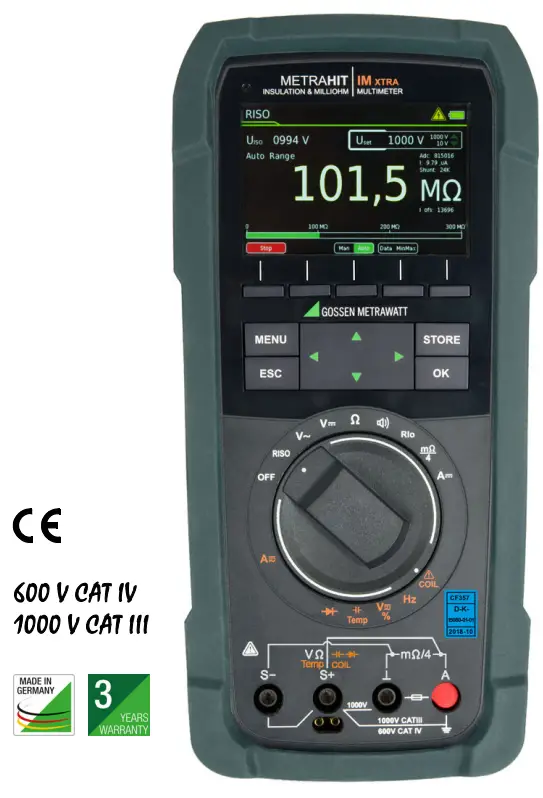
| Measuring category | 1000 V CAT III, 600 V CAT IV |
- Due to the system, the DC component indicated in the smallest measuring range (300 mV) has an offset. For a precise measurement of the DC component, please select measuring function VDC.
- with optional temperature sensors
- For 300,000 measured values, sampling rate adjustable from 0.1 seconds to 9hours
Standard Equipment (depending on Device Variant)
1 METRAHIT IM XTRA or METRAHIT IM E-DRIVE multimeter with rubber holster
1 Remote probe with start/stop and store/send functions
1 Type KS17-2 cable set: 1 pair of safety measurement cables with 4 mm test tip red/black
1 Type KC4 Kelvin clip, 1 pair (only METRAHIT IM XTRA)
1 Type KC&S Kelvin clip and Kelvin probe (only METRAHIT IM EDRIVE)
1 Quick change, rechargeable lithium polymer battery with micro USB charging socket
1 USB mains power pack (5 V DC, 2 A) with cable and micro USB charging plug
1 DAkkS calibration certificate
1 Hard case for the multimeter and accessories
1 Condensed operating instructions, German/English
– Comprehensive operating instructions in German and English available on the Internet for download at www.gossenmetrawatt.com
1 Card with registration key for the software
![]()
Overview Supply
| Accessories | Type | Article No. | M273S | M274S |
| METRAHIT IM XTRA | M273D | |||
| METRAHIT IM E-DRIVE BT | M274B | X | ||
| Lilon module & USB charger | Z270A+ | X | X | |
| Mains module with electrical isolation and USB charger | 0 | 0 | ||
| Remote probe | Z270S | Z270S | X | X |
| Cable set | KS17-2 | GTY362003 P0002 | X | X |
| 1 pair Kelvin clips | KC4 | Z227A | X | 0 |
| 1 pair Kelvin probes | KC27 | Z227B | 0 | 0 |
| 1 Kelvin clip & 1 Kelvin probe | KC&S | Z227C | — | X |
| Hard case | HC40 | Z270K | X | X |
| COIL Adapter 10 pH „, 50 mH | COIL Adapter 50mH | Z270F | 0 | 0 |
| COIL Adapter 10 pH „, 500 mH | COIL Adapter XTRA | Z270M | 0 | 0 |
| Adapter cable 4 mm male to 6 mm female | AK-4M16F | Z110L | 0 | 0 |
| IZYTRONIO Business Starter Licence | S101S & Z956A | S101S & Z956A | X | X |
Legend
X = Standard
O = Option
— = not possible, not provided for
Characteristic Values
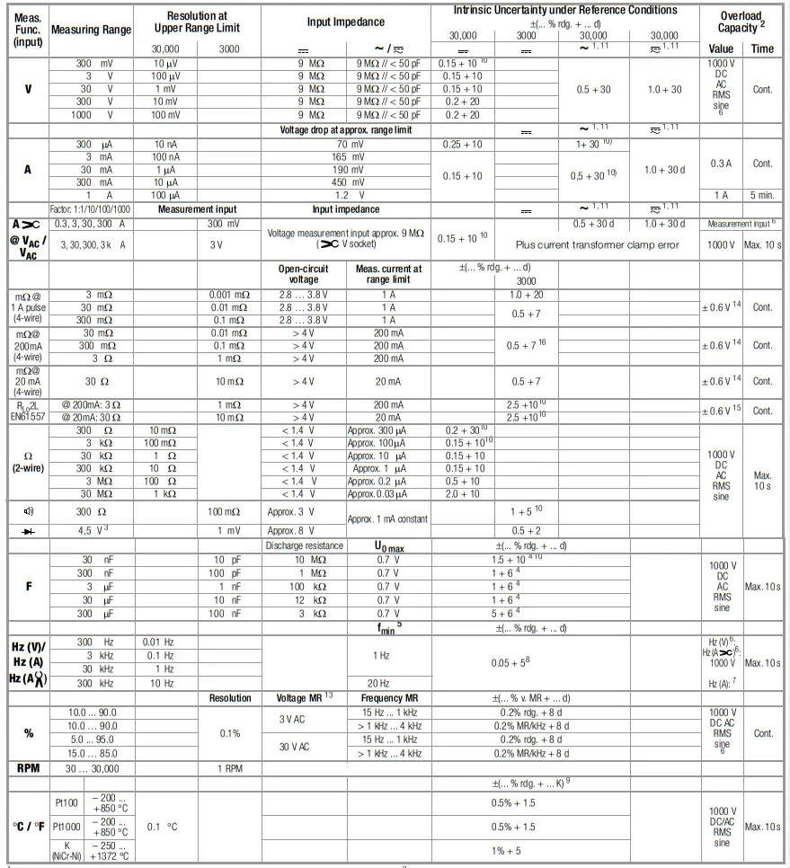
- 15 … 45 … 65 Hz … 100 kHz sinusoidal. For influence see page 5.
- At 0° … + 40 °C
- Display of up to max. 5.1 V, “OL” in excess of 5.1 V.
- Applies to measurements at film capacitors during battery operation
- Lowest measurable frequency for sinusoidal measuring signals symmetrical to the zero point
- Overload capacity of the voltage measurement input: power limiting: frequency x voltage max. 6 x 10⁶ V x Hz at > 100 V
- Overload capacity of the current measurement input: See current measuring ranges for maximum current values.
- Input sensitivity, sinusoidal signal: 10% to 100% of the voltage or current measuring range, restriction in mV measuring range: 30% rdg. The voltage measuring ranges with max. 10 kHz apply in the A measuring range.
- Plus sensor deviation
- With ZERO function active
- Accuracy applies as from 1 % of MR; due to the TRMS converter, values < 50 digits are suppressed in the zero point.
- 10 minute cool-down period
- Required signal range: 30% to 100% of the voltage measuring range
- The integrated FF1A/1000 V fuse blows in the event of overloading
- The integrated FF0.315A/1000 V fuse blows in the event of overloading
- For measuring range 30 mΩ and 300 mΩ with function TComp active
Insulation Measurement
| Measuring Range | Resolution | Nominal Voltage UISO | Intrinsic Uncer- tainty at Reference Conditions ±(% rdg. + d) |
| 3 … 1000 V ≅1 | Ri = 1MW | 3 + 3 | |
| 300 kW | 0.1 kΩ | 50/100/250/500 V | 2 + 10 |
| 3 MW | 1 kΩ | 50/100/250/500/1000 V | 2 + 10 |
| 30 MW | 10 kΩ | 50/100/250/500/1000 V | 2 + 10 |
| 300 MW | 100 kΩ | 50/100/250/500/1000 V | 5 + 10 |
| 3000 MW | 1 MΩ | 250/500/1000 V | 5 + 10 |
1 TRMS interference voltage measurement (V AC+DC) with 1 MΩ input resistance, frequency response width: > 65 … 500 Hz, accuracy: 3% + 30 digits
| Measuring Function | Nom. Voltage UN | Open- Circuit Voltage Uo Max. | Nom. Cur- rent IN | Short- Circuit Cur- rent Ik | Acoustic Signal for | Overload Capacity | |
| Value | Time | ||||||
| Uint./MW@UISO | — | — | — | — | U > 1000 V | 1000 V | Cont. |
| MW@UISO | 50 100 | 1.2x UIso | 1.0 mA | < 1.4 mA | U > 1000 V | 1000 V | 10 s |
| 250 500 V 1000 V | 1.12x UIso | ||||||
Short-Circuited Coil Test (only with optional COIL adapter)
| Measuring Range | Resolution | Nominal Voltage UISO | Intrinsic Uncer- tainty at Reference Conditions ±(% rdg. + d) |
| 0.3 … 1000 V | Ri = 1MW | 3 + 30 > 100 digits | |
| 10.0 30.9 μs | 0.1 [μs] | 1000 V | 10 + 5 digits |
| 31 … 250 μs | 1 [μs] |
1 TRMS interference voltage measurement (V AC+DC) with 1 M input resistance, frequency response width: > 65 … 500 Hz, accuracy: 3% + 30 digits
2) The time value may vary for differnt COIL adapters by up to 10 %. This has no influence whatsoever if you perform the measurements with the same COIL adapter and compare them with each other.
Inductance measuring ranges of optional COIL adapters:
- COIL adapter XTRA (Z270M): 10 μH up to 5 H
- COIL adapter 50mH (Z270F): 10 μH up to 50 mH
Internal Clock
| Time format Resolution Accuracy Temperature influence | DD.MM.YYYY hh:mm:ss 0.1 s (measured values time stamp) ±1 minute per month 50 ppm/K |
Reference Conditions
| Ambient temperature Relative humidity Measured quantity frequency Measured quantity waveform Supply voltage | +23 °C 2K 40% …… 75% 45 Hz …. 65 Hz Sinusoidal 4.0 V ±0.1 V |
Influencing Quantities and Influence Error
| Influencing Quantity | Sphere of Influence | Measured Quantity / Measuring Range 1 | Influence Error (…% rdg. + … d) / 10 K |
| Temperature | 0 °C … +21 °C and +25 °C … +40 °C | V | 0.2 + 5 |
| V≅ | 0.4 + 5 | ||
| 300 W … 3 MW | 0.5 + 5 | ||
| 30 MW | 1 + 5 | ||
| mA/A | 0.5 + 5 | ||
| mA/A≅ | 0.8 + 5 | ||
| 30 nF … 300 mF | 2 + 5 | ||
| Hz | 0.2 + 5 | ||
| °C/°F (Pt100/Pt1000) | 0.5 + 5 |
1 With zero balancing
Frequency Influence for VAC VAC+DC Voltage Ranges
| Deviation 1 | |||
| Frequency Range | 300 mV range ± (… % rdg. + … d) | 3 V, 30 V, 300 V range 2 ± (… % rdg. + … d) | 1000 V range 2 ± (… % rdg.) |
| 15 Hz … 45 Hz | 2 + 30 | 2 + 30 | 2 + 30 |
| > 65 Hz … 1 kHz | 0.5 + 30 | 0.5 + 30 | 1 + 30 |
| > 1 kHz … 10 kHz | 2 + 30 | 1.5 + 30 | 10 + 30 |
| > 10 kHz … 20 kHz | 3 + 30 | 1.5 + 30 | — |
| > 20 kHz … 50 kHz | 3 + 30 | 5 + 30 | — |
| > 50 kHz … 100 kHz | 10 + 30 | 10 + 30 | — |
- For sinusoidal input signals > 10% to 100% of the range (mV range: as of 30% of range, at 1% to 10% of the range: f < 50 kHz, intrinsic error increased by 0.2% of
the upper range limit. - Overload capacity of the voltage measurement input: power limiting: frequency x voltage max. 6 x 10⁶ V x Hz at > 100 V
Frequency Influence for IAC / IAC+DC Current Measuring Ranges
| Influence Error 1 | ||
| Frequency Range | 300 mA to 300 mA ± (… % rdg. + … digits) | 1 A range ± (… % rdg. + … digits) |
| 15 Hz … 45 Hz | 2 + 30 | 2 + 30 |
| > 65 Hz … 1 kHz | 1 + 30 | 1 + 30 |
| > 1 kHz … 2 kHz | 1 + 30 | 1 + 30 |
| > 2 kHz … 5kHz | 1 + 30 | 3 + 30 |
| > 5 kHz … 10 kHz | 5 + 30 | 5 + 30 |
1 For sinusoidal input signals > 10% to 100% of the range.
| Influencing Quantity | Sphere of Influence | Measured Quantity / Measuring Range | Influence Error 1 |
| Crest Factor CF | 1 … 3 | V ∼, A∼ | ± 1% rdg. |
| > 3 … 5 | ± 3% rdg. |
1 Except for sinusoidal waveform
| Influencing Quantity | Sphere of Influence | Measured Quantity | Influence Error |
| Relative Atmospheric Humidity | 75% 3 days instrument off | V, A, W, Ω F, Hz, °C | 1 x intrinsic uncertainty |
| Battery Voltage | ditto | Included in intrinsic uncertainty |
| Influencing Quantity | Sphere of Influence | Measured Qty. / Measuring Range | Damping |
| Common Mode Interference Voltage | Interference quantity max. 1000 V∼ | V | > 90 dB |
| Interference quantity max. 1000 V∼ 50 Hz … 60 Hz, sinusoidal | 3 V∼ | > 90 dB | |
| 30, 300 V∼ | > 150 dB | ||
| 1000 V | > 150 dB | ||
| Series Mode Interference Voltage | Interference quantity: V ∼ , respective nominal value of the measuring range, max. 1000 V ∼, 50 Hz … 60 Hz sinu- soidal | V | > 50 dB |
| Interference quantity max. 1000 V | V∼ | > 50 dB |
Response Time (after manual range selection)
| Measured Quantity / Measuring Range | Digital Display Response Time | Measured Quantity Jump Function |
| V A | 1.5 s | From 0 to 80% of upper range limit value |
| 300 W … 3 MW | 2s | From ¥ to 50% of upper range limit value |
| 30 MW, MW@UISO | Max. 5 s | |
| Continuity | < 50 ms | |
| °C (Pt 100) | Max. 3 s | |
| 1.5 s | ||
| 30 nF … 300 mF | Max. 5 s | From 0 to 50% of upper range limit value |
| >10 Hz | 1.5 s |
Fuse
| Current measuring ranges & 4L mW measuring ranges | F1: FF 1 A/1000 V AC/DC, 6.3 x 32 mm Fuse with breaking capacity of 30 kA at 1000 V AC/DC, protects the current measurement input in the 300 mA to 1 A ranges |
| 2L mW measuring ranges | F2: FF 0,315 A/1000 V 6.3 x 32 mm Fuse with breaking capacity of 30 kA at 1000 V AC/DC |
Display
TFT color graphic display (55 x 36 mm) with analog and digital display including unit of measure, type of current and various special functions
Background Illumination
Activated background illumination can be regulated by means of a light sensor.
Analog Bar Graph
| Scaling | Linear |
| Polarity display | With automatic switching |
| Measuring rate | 40 measurements per second and display refresh |
Digital Measured Value Display
| Resolution /char. height Number of places | 320 x 480 dots, 12 mm 31,000 / 3100 4¾-place in the V, A, Hz and W measuring functions, depending on parameter setting |
| Overflow display | “OL” is displayed for ³ 31,000 digits or ³ 3100 digits |
| Polarity display | “–” (minus sign) is displayed if plus pole is connected to “⊥” |
| Measuring rate | 10 and 40 measurements per second with the Min-Max function except for the capacitance, frequency and duty cycle measuring functions |
| Refresh Rate | 2 times per second, every 500 ms |
Electrical Safety
| Protection category | II per EN 61010-1:2010/VDE 04111:2011 |
| Measuring category | CAT III CAT IV |
| Nominal Voltage | 1000 V 600 V |
| Pollution degree | 2 |
| Test voltage | 7.4 kV~ per EN 61010-1:2011/VDE 0411-1:2011 |
Power Supply
| Battery module | 3.7 V, 4000 mAh, LiPo (approx. 25% self-discharge per year) |
| Service life | Approx. 20 hours (without MWISO mea- surement / RLo / R 4-wire) |
| Battery indicator | Battery capacity display via battery |
| Power OFF function | The multimeter is switched off automatically: – When battery voltage drops to below approx. 3.6 V – If none of the keys or the rotary switch are activated for an adjustable duration (10 to 59 min.) and the multimeter is not in the continuous operation mode |
Rechargeable battery modules can only be recharged externally.
| Measuring Function | Nominal Voltage UN | Resistance of the DUT | Service Life in Hours | Number of Possible Mea- surements with Nominal Current per VDE 0413 |
| V | 20 1 | |||
| V∼ | 15 1 | |||
| RINS | 100 V | 1 MΩ | 5 | |
| 100 V | 100 kΩ | 300 | ||
| 500 V | 500 kΩ | 60 | ||
| 1000 V | 2 MΩ | 20 |
Electromagnetic Compatibility (EMC)
Interference emission EN 61326-1:2013 class B
Interference immunity EN 61326-1:2013
Short-term measured value deviation of up to 10% may occur during electromagnetic interference thus reducing the specified operating quality.
Ambient Conditions
| Accuracy range Operating temperatures (Storage temperature with batteries) | 0 °C to +40 °C -10 °C … +50 °C -20 °C … +50 °C with rubber holster |
| Storage temperatures | -25 °C … +70 °C (without battery) |
| Relative humidity | 40 to 75%, no condensation allowed |
| Elevation | To 2000 m |
| Deployment | Indoors, except within specified ambient conditions |
Data Interface
| Type | Bluetooth 4.2 |
| Frequency band | 2.402 … 2.480 GHz |
| Transmitting power Functions | max. 91 mW – Query measuring functions and parameters – Query momentary measurement data |
Internal Measured Value Storage
| Housing Dimensions | Impact resistant plastic (ABS) 235 x 105 x 56 mm (without rubber holster) |
| Weight Protection | Approx. 0.7 kg with battery module Housing: IP 52 (pressure equalization by means of the housing) Excerpt from table on the meaning of IP Codes |
| IP XY (1st digit X) | Protection against foreign object entry | IP XY (2nd digit Y) | Protection against the penetration of water |
| 0 | not protected | 0 | not protected |
| 1 | ³ 50.0 mm dia. | 1 | vertically falling drops |
| 2 | ³ 12.5 mm dia. | 2 | vertically falling drops with enclosure tilted 15° |
| 3 | ³ 2.5 mm dia. | 3 | spraying water |
| 4 | ³ 1.0 mm dia. | 4 | splashing water |
| 5 | dust protected | 5 | water jets |
Applicable Regulations and Standards
| DIN EN 61010– VDE 0411-1 | Safety requirements for electrical equipment for measurement, control and laboratory use – Part 1: General requirements |
| DIN EN 61326-1 VDE 0843-20-1 | Electrical equipment for measurement, control and laboratory use – EMC requirements – Part 1: General requirements |
| DIN EN 60529 VDE 0470-1 | Test instruments and test procedures – degrees of protection provided by enclosures (IP code) |
| DIN EN 61557-1 VDE 0413-1 | Electrical safety in low voltage distribution systems up to 1000 V a.c. and 1500 V d.c. – Equipment for testing, measuring or moni- toring of protective measures Part 1: General requirements |
| DIN EN 61557-2 VDE 0413-2 | Part 2: Insulation resistance |
| DIN EN 61557-4 VDE 0413-4 | Part 4: Resistance of earth connection and equipotential bonding |
METRAHIT IM XTRA
with Accessory COIL Adapter 50mH (Z270F)
METRAHIT IM XTRA
with Accessory COIL Adapter XTRA (Z270M)
METRAHITIM XTRA & METRAHITIM E-DRIVE Isolation Tester, Milliohmmeter, TRMS Multimeter, Short-Circuited Coil Tester
Order Information
| Designation | Type | Article Number |
| multimeter, milliohm-meter and isolation resistance tester (COIL Ready) with graphic display, Bluetooth, and software IZYTRONIQ Business Starter. R-ISO up to 1kV & mW @ 200 mA 2-wire & mW @ 200 mA 4-wire & mW @ 1 A 4-wire, delivery content comprises multimeter (M273D), push-button probe, cable set, kelvin-clips, hard case,rechargeable lithium battery, USB wall supply, calibration certificate, and SW licence. | METRAHIT IM XTRA BT | M273S |
| All-in-One Tester for electric machines, multimeter, milliohm-meter and isolation resis- tance tester (COIL Ready) with graphic display, Bluetooth, and software IZYTRONIQ Business Starter. R-ISO up to 1kV & mW @ 200 mA 2-wire & mW @ 200 mA 4-wire & mW @ 1 A 4-wire, delivery content comprises multimeter (M274B), push-button probe, cable set, each one kelvin-clip and kelvin-probe, hard case, rechargeable lith-ium battery, USB wall supply, calibration certificate, and SW licence. | METRAHIT IM E-DRIVE BT | M274S |
| Accessory cables and adapters | ||
| Cable set (1 pair of measurement cables) 1.2 m, with VDE-GS mark, 600 V CAT IV 1 A 1, 1000 V CAT III 1 A 1 1000 V CAT II 16 A 2 | KS17-2 | GTY3620034P0002 |
| Cable set with 2 mm diameter steel tips and 120 cm cable, 1000 V / CAT III | KS17-S | Z110H |
| Adapter cable 4 mm male to 6 mm female for the charging plug of hybrid and electric vehicles | AK-4M/6F | Z110L |
| Cable set including Remote probe, clamps and US test probes (1000 V CAT II / III 20 A) | KS-NTS | Z110W |
| Alligator clips (1 pair) for KS17-2 1000 V CAT III 16 A | KY95-3 | Z110J |
| Current clamp sensor, 10 mA ¼ 100 A, 1 mV/10 mA, clamp opening: 15 mm dia. | WZ12B | Z219B |
| Kelvin clips (1 set of 2 ea.) for 4-pole connection of low-resistance DUTs, cable length: 150 cm | KC4 | Z227A |
| Kelvin probes (1 set of 2 ea.) with double steel tips for 4-pole connection of low-resistance DUTs | KC27 | Z227B |
| Set including 1 Kelvin clip and 1 Kelvin probe, as well as 2 stainless steel tips for 4-wire measurement, 120 cm cable length with 4 mm angle plugs | KC&S | Z227C |
| Rechargeable lithium polymer battery M27x 14,8 Wh | Z270A | Z270A |
| Rechargeable lithium polymer battery M27x 14,8 Wh | Z270G | Z270G |
| USB+Power Module M27x | Z270E | Z270E |
| Charger M27x | Z270L | Z270L |
| Coil adapter for interturn short circuit detection at inductivities from 10 μH to 50 mH | COIL Adapter 50mH | Z270F |
| Coil adapter for interturn short circuit detection at inductivities from 10 μH to 5 H | COIL Adapter XTRA | Z270M |
| Probe with keys | Z270S | Z270S |
| AC/DC current clamp sensor, 5 mA … 30 A, 100 mV/A | CP30 | Z201B |
| AC/DC current clamp sensor, 0.5 … 30 A, 5 … 300 A, 10 mV/A, 1 mV/A | CP330 | Z202B |
| AC/DC current clamp sensor, 0.5 … 100 A, 5 … 1000 A, 10 mV/A, 1 mV/A | CP1100 | Z203B |
| AC/DC current clamp sensor, 0.5 … 125 A, 5 … 1250 A, 10 mV/A, 1 mV/A | CP1800 | Z204A |
| Accessories for temperature measurement with resistance thermometer | ||
| Pt100 temperature sensor for surface and immersion measurements, –40 ¼ +600 °C | Z3409 | GTZ3409000R0001 |
| Pt1000 temperature sensor for measurement in gases and liquids, –50 ¼ +220 °C (for servicing household appliances) | TF220 | Z102A |
| Pt100 oven sensor, –50 ¼ +550 °C | TF550 | GTZ3408000R0001 |
| Protection and transport accessories | ||
| Hard case with foam insert and compartments for 1 METRAHIT IM XTRA or METRAHIT IME-DRIVE and 2 batteries, as well as 2 universal compartments for accessories. | HC40 | Z270K |
| Replacement fuses | ||
| Fuse F1 for current measuring ranges FF1 A/1000 V AC/DC (10 pcs.) | FF1 A/1000 V AC/DC | Z109O |
| Fuse F2 for milliohm measuring ranges FF0,315 A/1000 V AC/DC (10 pcs.) | FF0,315 A/1000 V AC/DC | Z109P |
- With plugged on safety caps
- Without plugged on safety caps
For additional information regarding accessories please refer to:
- Measuring Instruments and Testers catalog
- www.gossenmetrawatt.com
© GMC-I Messtechnik GmbH
Edited in Germany, Subject to change without notice / Errors excepted.
All trademarks, registered trademarks, logos, product names, and company names are property of their respective owners.
![]()
![]()
GMC-I Messtechnik GmbH
Südwestpark 15
90449 Nürnberg • Germany
Phone +49 911 8602-111
Fax +49 911 8602-777
E-Mail: [email protected]
www.gossenmetrawatt.com
![]()


