LMI TECHNOLOGIES Gocator 2600 Series Smart 3D Laser Line Profilers User Guide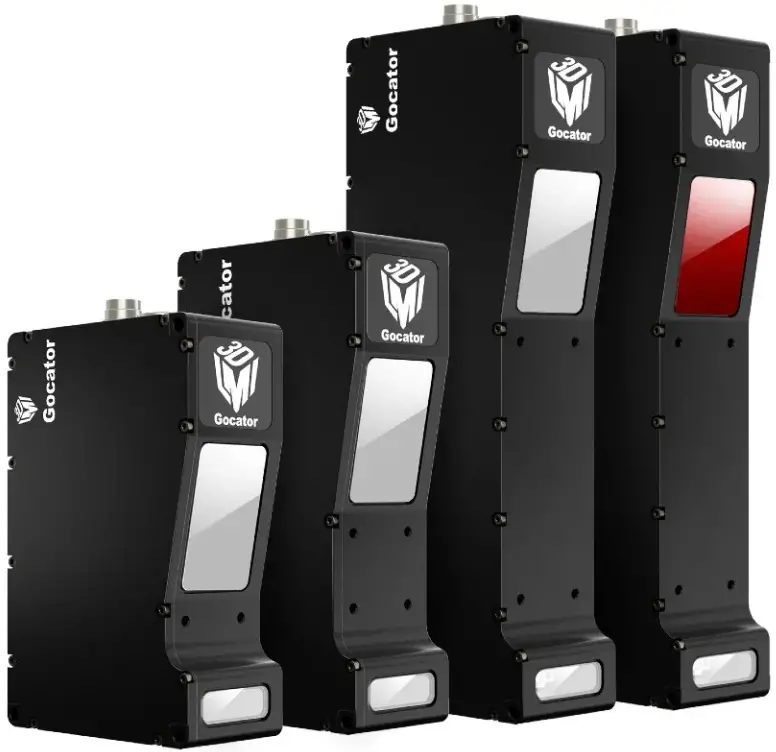
MOUNTING
NOTE: Mounting the Gocator is recommended before applying power. Ensure that a proper earth ground is established and that a heat sink is properly installed before applying power.
Side mount (shown): Use three 5 mm bolts of appropriate length.
Top mount: Use three or five M4 screws of suitable length (modeldependant). Recommended thread engagement into the housing is 4.7 mm.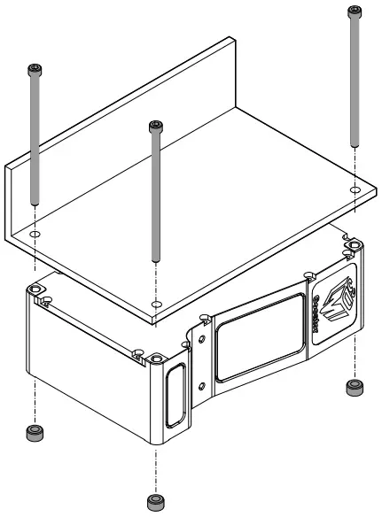
Do not occlude camera’s view of the laser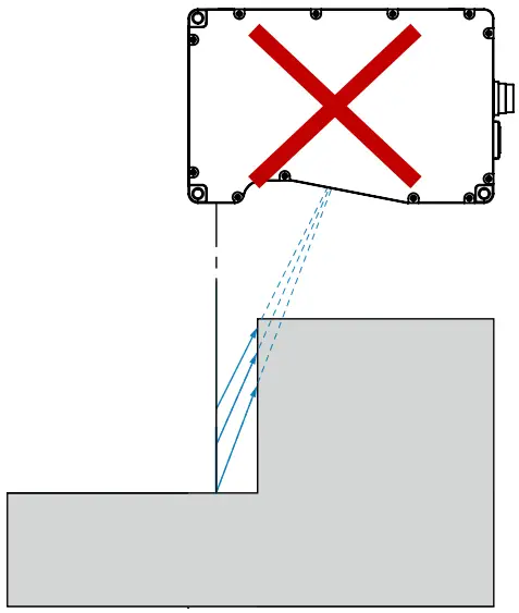
Do not install near surfaces that might create unexpected laser reflections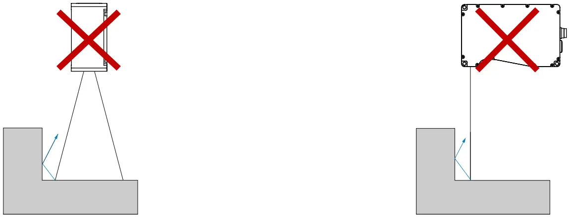
CONNECTING GOCATOR TO A HOST COMPUTER
Standalone System
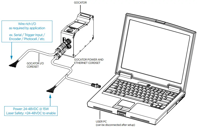
![]() Always power down sensor before removing cables from the sensor
Always power down sensor before removing cables from the sensor
Dual / Multi-Sensor System
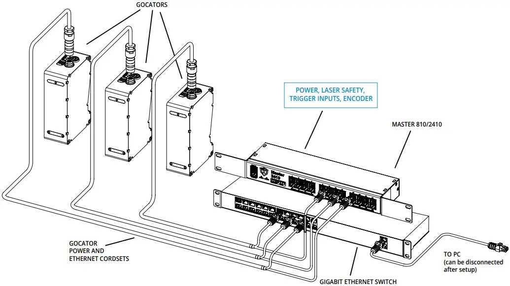
![]() Leave protective caps on any connectors that are not used.
Leave protective caps on any connectors that are not used.
Connector Pin Details
| Power/LAN Pin | Function | Conductor Color (Standard) | Conductor Color (High Flex) |
View: Looking into the connector on the sensor.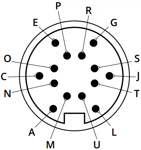 | GND_24-48V | White/Orange & Black | Orange/Red |
| GND_24-48V | Orange/Black | Orange/Black | |
| DC_24-48V | White/Green & Black | Green/Red | |
| DC_24-48V | Green/Black | Green/Black | |
| Safety- | White/Blue & Black | Blue/Black | |
| Safety+ | Blue/Black | Blue/Red | |
| Sync+* | White/Brown & Black | Brown/Red | |
| Sync-* | Brown/Black | Brown/Black | |
| Ethernet MX1+ | White/Orange | White/Orange | |
| Ethernet MX1- | Orange | Orange | |
| Ethernet MX2+ | White/Green | White/Green | |
| Ethernet MX2- | Green | Green | |
| Ethernet MX3- | White/Blue | White/Blue | |
| Ethernet MX3+ | Blue | Blue | |
| Ethernet MX4+ | White/Brown | White/Brown | |
| Ethernet MX4- | Brown | Brown | |
| * The Sync leads are not connected in the open wire versions of the Power/LAN cordsets. | |||
| I/O Pin | Function | Conductor Color (Standard) | Conductor Color (High Flex) |
View: Looking into the connector on the sensor.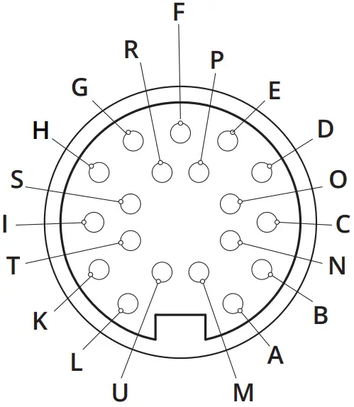 | Trigger_in+ | Grey | Blue/Red |
| Trigger_in- | Pink | Blue/Black | |
| Out_1+ (Digital Output 0) | Red | Brown/Red | |
| Out_1- (Digital Output 0) | Blue | Brown/Black | |
| Out_2+ (Digital Output 1) | Tan | Green/Red | |
| Out_2- (Digital Output 1) | Orange | Green/Black | |
| Encoder_A+ | White/Brown & Black | Pink/Red | |
| Encoder_A- | Brown/Black | Pink/Black | |
| Encoder_B+ | Black | Yellow/Red | |
| Encoder_B- | Violet | Yellow/Black | |
| Encoder_Z+ | White/Green & Black | White/Red | |
| Encoder_Z- | Green/Black | White/Black | |
| Serial_out+ | White | Purple/Red | |
| Serial_out- | Brown | Purple/Black | |
| Reserved | Blue/Black | Red | |
| Reserved | White/Blue & Black | Black | |
| Reserved | Green | Gray/Red | |
| Reserved | Yellow & Maroon/White | Gray/Black & Orange/Black | |
| Reserved | Maroon (not connected) | Orange/Red (not connected) | |
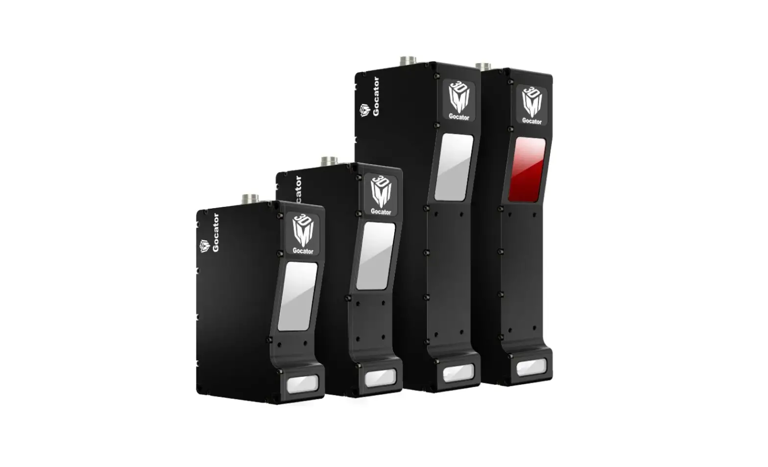
GOCATOR OVERVIEW
Each sensor model in the Gocator 2600 series is designed with a unique Clearance Distance (CD), Measurement Range (MR) and Field of View (FOV). Models have different numbers of mounting holes. Refer to the user manual for more information about your model.
LED Indicators
When starting the Gocator, the Power indicator and the Laser indicator (if safety is enabled) should light. If not, refer to the troubleshooting table below or the user manual.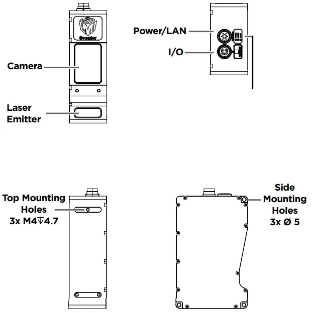
GROUNDING GOCATOR
Gocator housings should be grounded to the earth and the grounding shield of the Gocator I/O cordsets. Gocator sensors are designed to provide adequate grounding through the M4 screws. Always check grounding with a multi-meter to ensure electrical continuity between the mounting frame and the Gocator connectors.
The frame or electrical cabinet that the Gocator is mounted to must be connected to earth ground.
GROUNDING CORDSET (RECOMMENDED)
To minimize interference with other equipment, the Power & Ethernet or the Power & Ethernet to Master cordset (depending on cordset used in system) can be grounded by terminating the cordset shield before the split. The most effective grounding method is to use a 360-degree clamp. For instructions, see the user manual.
ELECTRICAL SAFETY
Minimize voltage potential between system ground (ground reference for I/O signals) and sensor ground Use shielded cables with shield grounded at both ends. Sensor housing should be connected to earth ground.
Use a suitable power supply
The +24-48V power supply used with Gocator 2600 sensors should be an isolated supply with inrush current protection.
Use care when handling powered devices
Wires connecting to the sensor should not be handled while the sensor is powered. Doing so may cause electrical shock to the user or damage to the equipment.
![]() Failure to adhere to the guidelines described in this section may result in electrical shock or equipment damage.
Failure to adhere to the guidelines described in this section may result in electrical shock or equipment damage.
LASER SAFETY
The full laser safety details including precautions, responsibilities and requirements are stated in the Gocator user manual. Use of controls or adjustments or performing procedures other than those specified in the user manual may result in hazardous radiation exposure.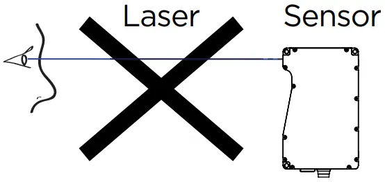
![]() The light emitted from these devices has been set in accordance with IEC60825. However, staring into the beam, whether directly or indirectly, must be avoided. IEC60825 classifies laser products into three different categories depending on light emitted, wavelength and eye safety.
The light emitted from these devices has been set in accordance with IEC60825. However, staring into the beam, whether directly or indirectly, must be avoided. IEC60825 classifies laser products into three different categories depending on light emitted, wavelength and eye safety.
This product is designated for use solely as a component and as such it does not fully comply with the standards relating to laser products specified in U.S. FDA CFR Title 21 part 1040 and IEC 60825-1.
- CLASS 2 LASER PRODUCT
LASER RADIATION
DO NOT STARE INTO THE BEAM - CLASS 3R LASER PRODUCT
LASER RADIATION
AVOID DIRECT EYE EXPOSURE - CLASS 3B LASER PRODUCT
LASER RADIATION
AVOID EXPOSURE TO THE BEAM
STARTING GOCATOR
NOTE: Gocator must be connected to a host computer in order to launch the user interface and set up the sensor.
Gocator sensors are configured by connecting with a web browser. For details on browser compatibility, see the user manual.
LAUNCHING THE INTERFACE
Step 1
Change network setting on the host computer
In Windows 10
- From the Start menu, launch the Settings app and click Network & Internet, and then click Change adapter options under Advanced network settings..
- Right-click desired network connection, and then click Properties.
- On the Networking tab, click Internet Protocol Version 4 (TCP/IPv4), and then click Properties.
- Select “Use the following IP address” option.
- Enter IP Address “192.168.1.5” and Subnet Mask “255.255.255.0”, then click OK.
In Mac OS 11
- Click Apple menu > System Preferences, and then click Network.
- In the list to the left, select Ethernet.
- Click Advanced, click Hardware, click the Configure pop-up menu, and set it to “Manually”.
- Enter IP Address “192.168.1.5” and Subnet Mask “255.255.255.0”, and then click Apply.
Gocator is shipped with the following default network configuration:
| Setting | Default |
| DCHP | Disabled |
| IP Address | 192.168.1.10 |
| Subnet Mask | 255.255.255.0 |
| Gateway | 0.0.0.0 |
Step 2
Open a web browser and enter the sensor address.
The Gocator interface loads.
RUNNING GOCATOR
Step 1
Select the Manage page.

Step 2
Ensure that Replay mode is off (slider set to left) and that the Laser Safety switch is enabled or the Laser Safety input is high. Press the Start button in the toolbar to start the sensor (a laser line should now be visible).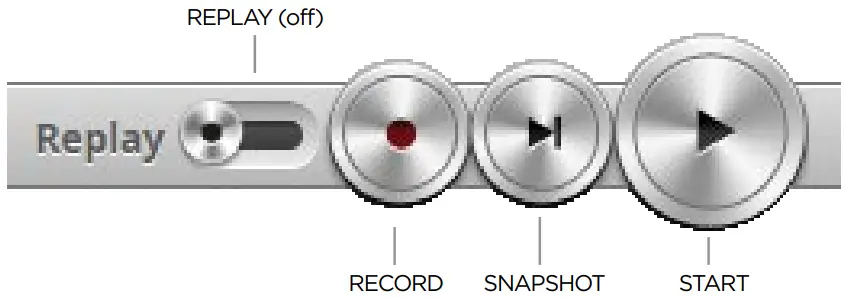
Step 3
Move target into the laser plane and measure!
NOTE
Gocator sensors can also interface directly with HexSight.
Refer to the HexSight Quick Start Guide for more information.
An example of the user interface in use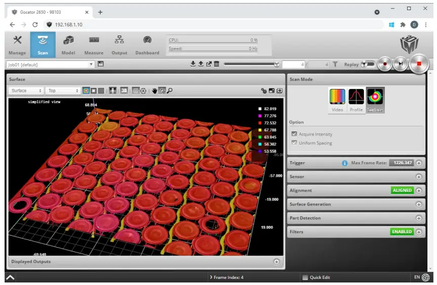
TROUBLESHOOTING
| PROBLEM | SUGGESTED RESOLUTION |
| Mechanical / Environmental | |
| The sensor is warm. |
|
| Connection | |
| When connecting with a web browser, the sensor is not found (page does not load). |
See Getting Started > Network and Sensor Setup in the Gocator user manual or your computer’s documentation on configuring a network adapter.
Unzip and run the Sensor Discovery Tool [Tools\Discovery\kDiscovery.exe] to verify that the sensor has the correct network settings. |
| When attempting to log in, the password is not accepted. |
Unzip and run the Sensor Discovery Tool [Tools\Discovery\kDiscovery.exe] to find the sensor on the network and click Factory Restore. WARNING: Performing a factory restore resets your configuration settings to their original values. These settings can be recovered from backup files if you have previously saved them. |
| Laser Profiling | |
| When the Play button is pressed, the sensor does not emit laser light. |
|
| The sensor emits laser light, but the Range indicator does not illuminate and/or points are not displayed in the data viewer. |
|
| The sensor CPU level is near 100%. |
|
Customer Support
Americas
LMI Technologies (Head Office)
Vancouver, Canada +1 604 636 1011
EMEAR
LMI Technologies GmbH
Germany Berlin,
+49 (0)3328 9360 0
Asia Pacific
LMI (Shanghai) Trading Co., Ltd.
China Shanghai,
+86 21 5441 0711
LMI Technologies has sales offices and distributors orldwide. All contact information is listed at
lmi3D.com/contact/
Proprietary
This document, submitted in confidence, contains proprietary information which shall not be reproduced or transferred to other documents or disclosed to others or used for manufacturing or any other purpose without prior written permission of LMI Technologies Inc.
No part of this publication may be copied, photocopied, reproduced, transmitted, transcribed, or reduced to any electronic medium or machine readable form without prior written consent of LMI Technologies Inc.
Trademarks and Restrictions
GocatorTM is a registered trademark of LMI Technologies Inc. Any other company or product names mentioned herein may be trademarks of their respective owners.
Information contained within this manual is subject to change without notice.
This product is designated for use solely as a component and as such it does not comply with the standards relating to laser products specified in U.S. FDA CFR Title 21 Part 1040.
©2021 LMI Technologies Inc. All rights reserved.


