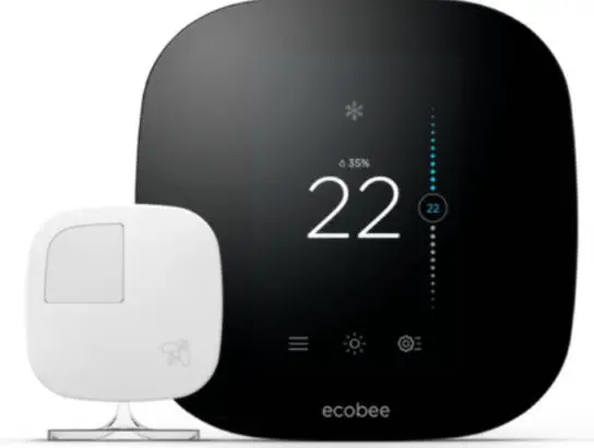
Carrier EB-STATE3LTCB-01 Ecobee Smart Thermostat Pro with Voice Control
Safety Considerations
- Read and follow manufacturer instructions carefully. Follow all local electrical codes during installation. All wiring must conform to local and national electrical codes. Improper wiring or installation may damage Thermostat.
- Recognize safety information. This is the safety-alert symbol . When you see this symbol on the equipment and in the instruction manual, be alert to the potential for personal injury.
- Understand the signal words DANGER, WARNING, and CAUTION. These words are used with the safety-alert symbol. DANGER identifies the most serious hazards which will result in severe personal injury or death.
- WARNING signifies a hazard which could result in personal injury or death.
- CAUTION is used to identify unsafe practices which may result in minor personal injury or product and property damage.
- NOTE is used to highlight suggestions which will result in enhanced installation, reliability, or operation.
Introduction
The ecobee Smart Thermostat Pro with voice control, Powered by Carrier and the ecobee3 lite Pro, Powered by Carrier provides your customers with freedom and flexibility to manage their home environment. These thermostats help homeowners conserve energy, save money and reduce their environmental impact. They support a furnace with AC and up to 2-stages of heat. For heat pumps (air to air or Geothermal) they support up to four stages of heat (2-stage heat pump, 2-stage auxiliary heat) and two stages of cool. For these systems the thermostats can control a single accessory, such as a humidifier, dehumidifier, ventilator, HRV or ERV. Also, the thermostats can be installed with the PEK if a C wire isn’t present. Additionally, the thermostats can control boilers with or without an AC. When connected to a boiler, the thermostats support up to 2-stage of heat and 2-stages of cool and a single accessory, such as a humidifier, dehumidifier ventilator, HRV or ERV. When used with a boiler they cannot be installed with the PEK if a C wire isn’t present, the C wire must come from the air handler, not the boiler.
How to use this document
The advanced installation and configuration instructions are intended to supplement the standard installation instructions shipped with the thermostat or available for download on www.HVACpartners.com. The advanced settings and configuration options detailed in this document are intended for professional installers only. Incorrect configuration may lead to improper operation and equipment damage. Each section of this document is outlined in the following structure:
Section Title
Location of this section within the thermostat menus. Image showing available features in this section on the thermostat.
Feature Title
- Feature Description
- Default Configuration
- Configuration Options
Image showing screen on the thermostat.
WARNING
ELECTRICAL OPERATION HAZARD
Failure to follow this warning could result in personal injury or death. Before installing, modifying, or servicing system, main electrical disconnect switch must be in the off position. There may be more than 1 disconnect switch. Lock out and tag switch with a suitable warning label.
CAUTION
ELECTRICAL OPERATION HAZARD
Failure to follow this caution may result in equipment damage or improper operation. Improper wiring or installation may damage the thermostat. Check to make sure wiring is connect before proceeding with installation or turning on unit.
Hardware Differences
Conventional System
For single stage heat and single stage cooling applications, 5 wires are required instead of the traditional 4.
A common wire to power is needed to power the thermostat. Additional wires are shown as dotted lines for 2-stage equipment. Most Carrier 2 stage furnace equipment can be operated with a single stage thermostat using the algorithm in the furnace circuit board to engage 2nd stage. While a 2-stage thermostat can control the equipment, it is preferred to allow the Carrier equipment to determine the staging by not connecting W2. See furnace installation instructions for heat staging setup.
Power Extender Kit (PEK)
The Power Extender Kit, also known as the PEK, allows the thermostat to operate with 4 wires instead of 5, which helps with retrofit applications. The thermostat has a PEK terminal which digitally combines the G and Y1 signal. The PEK device, which gets installed at the equipment, separates that combined signal back into separate 24v wires. The PEK can go from 5 to 6 wires or from 8 to 9 wires. It can always add one more wire to the available wires. The 4 wires at the thermostat should be wired as shown above. Additional wires would bypass the PEK and connect directly to the equipment.
Power Extender Kit (PEK)
In the example above, the PEK is shown with wire labels. The Red wire goes to Rc and the White wire goes to W. However, the Green wire, which is labeled G in the drawing does not go to G. Instead it becomes the common wire. The Yellow wire, labeled Y, goes to the PEK terminal.
Add-A-Wire Kit

The Venstar Add-a-Wire Kit, works similar to the PEK. Normally this would not be needed because the PEK comes with the ecobee. However, the PEK is limited to one extra wire and only one PEK can be used per system. Several Add-a-Wire Kits can be used if needed. Each wire in the wall can be split using the diode to take care of two terminals on the thermostat. The only rule is that R and C cannot be split. For example, if 6 wires are needed and only 4 wires are in the wall and you needed 6, two kits could accomplish it. A Fast-Stat Wiring Extender can be used instead of an Add-a-Wire. The Honeywell Wiresaver cannot be used since it has a proprietary language and only works with certain Honeywell thermostats.
Heat Pump With Auxiliary Heat
For a traditional heat pump, Y1 is the compressor and O/B is the reversing valve. During the startup process, the O/B should be configured to act as an O terminal with Carrier equipment, since the equipment defaults to heating and needs the reversing valve to be energized on a cooling call. W1 is used for the auxiliary heat – typically, electric resistance.
Boiler with Fan Coil
The ecobee thermostat can control two pieces of equipment where each has its own transformer, such as a fan coil with a boiler. Both Rc and Rh are needed in this application.
Air Conditioner with Boiler
Boiler-Only System
A boiler only system still needs a common. The best solution is to run a 3rd wire to the boiler and tie into the common. Many boilers will only have T-T terminals and not have a common terminal. In these cases, the common can be picked up directly from the transformer. If it is not possible to run a wire, Fast-Stat makes a different accessory called a Common Maker that can be used. The ecobee PEK, Venstar Add-a-Wire, or Fast-Stat Wiring Extender accessories mentioned above cannot be used. The W call gets piggy-backed on the common wire with the small black sender module installed at the thermostat. Then the Common Maker is installed at the boiler where it separates the W signal from the common.
Humidifier (1-wire)
When the accessory is NOT internally powered, it needs power from the furnace or fan coil. Connect one wire to the ACC+ terminal on the thermostat and the other wire should be connected to Common. Because there is already a common wire from the stat to the air handler, and since the humidifier is likely right next to the furnace, this is referred to as a 1-wire application because only one extra wire needs to run through the walls.
Dehumidification with DH or DEHUM Terminal (FV Fan Coil and Variable Speed Furnaces)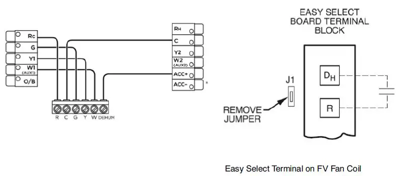
If the accessory terminals are not being used for a humidifier or whole house dehumidifier, then they may be used for the dehumidification feature integrated into Carrier FV fan coils and select variable speed furnaces. The ACC+ terminal will wire to the DH or DHUM terminal on the equipment in these applications. On the FV fan coils, remove jumper J1 from the Easy Select board to enable this feature. Please also note that the equipment is expecting DH or DHUM to be energized during normal operation and DE-ENERGIZED on a dehumidification call from the thermostat. It is a reverse logic input, as compared to Y, G, W, etc.
Initial Start-Up
When the thermostat is first powered up, or after resetting the stat, a bee will be buzzing around the screen. This will be followed by the start of the initial configuration.
Initial Start-Up –> Power Source
A standard furnace with A/C or a fan coil with heat pump will only have a single transformer and so only Rc is connected. It is important to note that in these applications, Rc must be used instead of Rh like some Carrier thermostats. If the heating and cooling equipment have separate transformers, such as a boiler with a fan coil and A/C, then both Rc and Rh are connected
Start-Up –> Wiring -> Standard
In rare cases, the thermostat will not be able to detect certain wires. When this happens they can be added manually by selecting modify and then the connected wires on the thermostat display.
Start-Up –> Wiring -> Accessory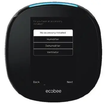
If an accessory is wired to the ACC terminals, the type of accessory must be selected. The screens that follow will depend on the selection made here.
Start-Up –> Dehum for Fan Coil or Furnace
Initial Start-Up –> Wiring -> Standard
During installation, the thermostat will automatically detect which terminals have wires connected. If something is incorrect, check the terminations at the thermostat backplate and at the equipment. In rare cases, the thermostat will not be able to detect certain wires. In this case they will need to be manually Modified on the screen. Select Modify and then select the wires that are connected. An example of this would be if a Venstar Add-A-Wire Kit is installed.
Initial Start-Up –> Wiring -> Accessory
Select which accessory is installed if any; No accessory, Humidifier, Dehumidifier, or Ventilator.
Initial Start-Up –> Wiring -> Accessory -> Dehumidifier for Fancoil or Furnace
When selecting dehumidifier for using the equipment’s DHUM or DH terminal, select the appropriate relay action. A fan coil or furnace will dehumidify when the Dehum input is Open.
Initial Start-Up –> Heat Pump
Carrier heat pumps need the reversing valve (O terminal) to be energized on a cooling call, so On cool should be selected. Some other equipment manufacturers could energize the reversing valve on a heat call.
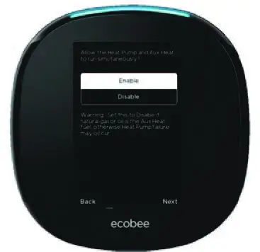
Select Enable If the auxiliary heat source is electric resistance and it is desired to have heat pump and electric heat to run at the same time. The system will provide heat pump heating at lower stage and then turn on electric heat along with the heat pump at higher stages. If it is a “dual fuel system,” meaning the auxiliary heat is a fossil fuel furnace, including natural gas, propane, or oil, then select Disable. Do not run the compressor and furnace at the same time to condition the home.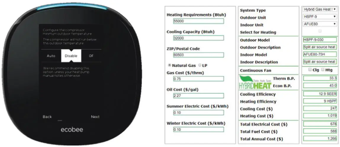
The minimum compressor outdoor temperature is based on the specific model of heat pump used in the system. Nearly all heat pumps can operate in the heating mode down to at least 17 degrees, as this temperature, along with 47 degrees, are the two AHRI standard testing points. The best temperature to disable the compressor depends on a lot of factors. If the auxiliary heat is electric resistance, then shut off the compressor when either…
a. The manufacturer has a published lowest operating temperature (for example, our 5-stage inverters can only run down to 10 degrees) or
b. The COP of the heat pump drops below 1.0, which is the COP of electric resistance heat Until that low temperature is reached, it is best to use the heat pump as the primary heat source and use the electric resistance as additional stages. Then below that temperature, shut off the compressor and use the electric heat only.
If the auxiliary heat is fossil fuel, then consider the cost of the fuel vs the cost of electricity, as well as the load of the house, the size of the equipment, and the models of the equipment. The online OpCost Calculator found on HVAC Partners can be used to determine the “thermal balance point” and the “economic balance point.” This tool takes only a couple of minutes to use. The thermal balance point is the outdoor temperature at which the heat pump can no longer handle the load of the house on its own. The economic balance point is the outdoor temperature at which the furnace would be less expensive to run. Set the thermostat for the higher of these two numbers, so 43 degrees in the example above.
Initial Start-Up –> Furnace
The fan should be controlled by the furnace for all current CBP and ICP furnaces. This allows the furnace to delay the fan on a W1 allowing the heat exchanger to warm-up before engaging airflow so the occupants do not get a blast of cold air. This setting only affects the gas heat startup sequence, it will not delay continuous fan or ventilation schedules, etc.
Initial Start-Up –> Humidifier
Typically, Steam should be selected as the humidifier choice even when an evaporative humidifier is installed. The ONLY difference between the two choices is that steam provides the option to humidify with fan. There are no other differences.
Installation Settings > Equipment > Humidifier > DeHum for Fan Coil or Furnace
When this feature is wired and set up along with AC Overcool Max, it allows multiple modes of cooling operation, including temperature only demand, dehumidification demand, and both. When the DH or DHUM terminal on the equipment is energized, it will slow down the variable speed blower to increase latent capacity of the evaporator coil, while reducing sensible capacity.
Installation Settings > Thresholds > Cool Dissipation
Cool Dissipation Time is default on, but the feature should only be used in very dry climates, such as Phoenix or Las Vegas. For the rest of the country, the fan should not to run at all after the cooling cycle is over. Setting the Cool Dissipation Time from Auto to 0 will allow the moisture on the evaporator coil to run down into the drain pain and leave the system. If the fan were to continue running, much of that moisture would re-evaporate back into the home. The graph on the right illustrates humidity going back into the home after a cooling cycle as the fan blows air across a wet evaporator.
Installation Settings > Thresholds > Reverse Staging

The Compressor Staging and Heat Staging settings work the same. If Reverse Staging is enabled, then the installer must configure values for Stage 2 delta, which is the space temperature deviation required to engage second stage. It is recommended that a Stage 2 Delta of TWO degrees be used when stage 1 was previously set for the standard half degree. This will allow the maximum runtime with just stage 1 operational which will minimize electrical usage and maximize dehumidification. Standard staging should be selected for geothermal systems. Standard Staging example: If there is a 74 degree cooling setpoint the 1st stage of cooling will energize when the room temperature climbs to 74.5 degrees. Then, if the temperature continues to climb to 76 degrees, the 2nd stage will come on. Then both will run together until the room temperature is satisfied at 74.
Reverse staging works example: If there is a 74 degree cooling setpoint the 1st stage of cooling will energize when we reach 74.5 degrees. Then, if the temperature continues to climb to 76 degrees, the 2nd stage will come on. Instead of both stages running to finish the cycle together, stage 2 will de-energize when the room temperature gets back down to 74.5 degrees. Stage 1 then finishes on its own until the room temperature is satisfied at 74. This helps get a longer total run cycle. If the space temperature continues to climb to 76 degrees, then stage 2 could be re-energized if needed.
Installation Settings > Thresholds > Heat Pump Optimization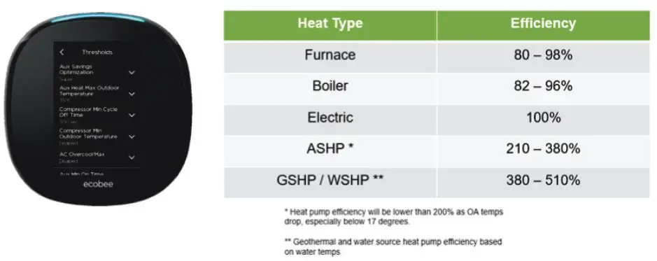
There are lot of settings related to heat pump optimization located in different areas of the thermostat setup. To be energy efficient, a big goal is to minimize the use of auxiliary electric resistance heat. As shown in the table above, a heat pump is often 2 to 3 times more efficient that electric heat, and since both use electricity at the same price, electric heat should only be used when it has to be used.

ecobee has an Auxiliary Savings Optimization algorithm with settings that are in language that is supposed to be homeowner friendly. Essentially this setting determines how many degrees out of setpoint before auxiliary heat will be engaged. It starts at a half degree with Minimum, but up to 2.5 degrees if set on Maximum.
The Auxiliary Heat Maximum Outdoor Temperature specifies when the heat pump should be able to handle the heating load solo without the need for auxiliary electric heat to assist. Aux heat will be locked out above this temperature. The OpCost Calculator mentioned on page 13 above can be used to determine the “Thermal Break Point” based on the house load and the heat pump model selected. The “Thermal Break Point” number often varies between 10 and 35 degrees. The default number is conservatively high at 35, and this should be lowered for most modern systems.
Alternatively, the house’s load profile can be manually plotted on the balance point worksheet in the product data book for each heat pump.
If Manual staging is selected instead of Automatic, then 5 additional staging options for the Auxiliary heat need to be configured. Unlike straight cooling projects where Manual Staging is recommended be enabled so Reverse Staging could be utilized, the same recommendation is not made for heat pumps. The Auxiliary Staging adds an extra layer of complexity into the mix, especially if there are 2 compression stages plus 2 auxiliary stages, so Automatic Staging should be selected on heat pump applications.
Installation Settings > Thresholds > Thermal Protect

The Thermal Protect range tells the thermostat the maximum difference allowed between the thermostat and hottest or coldest rooms in the home. If a sensor measures a temperature that is significantly outside of this range, it probably means the reading is inaccurate. The thermostat will ignore this inaccurate reading to prevent the heating or cooling from running excessively. This setting is adjustable from 10 to 25 degrees.
Installation Settings > Thresholds > Installer Code
It is recommended that professionally installed thermostats be locked out by enabling the Installer Code. This prevents the homeowner from accidentally changing any of the settings in the Equipment, Thresholds, or Test Equipment settings. This lockout feature is separate from the Access Control lockout and password that the homeowner can set for the homeowner settings. Write this code down as it is not well documented or easy to find online. The code cannot be changed, as is the same for all thermostats.
Installation Settings > Sensor Settings
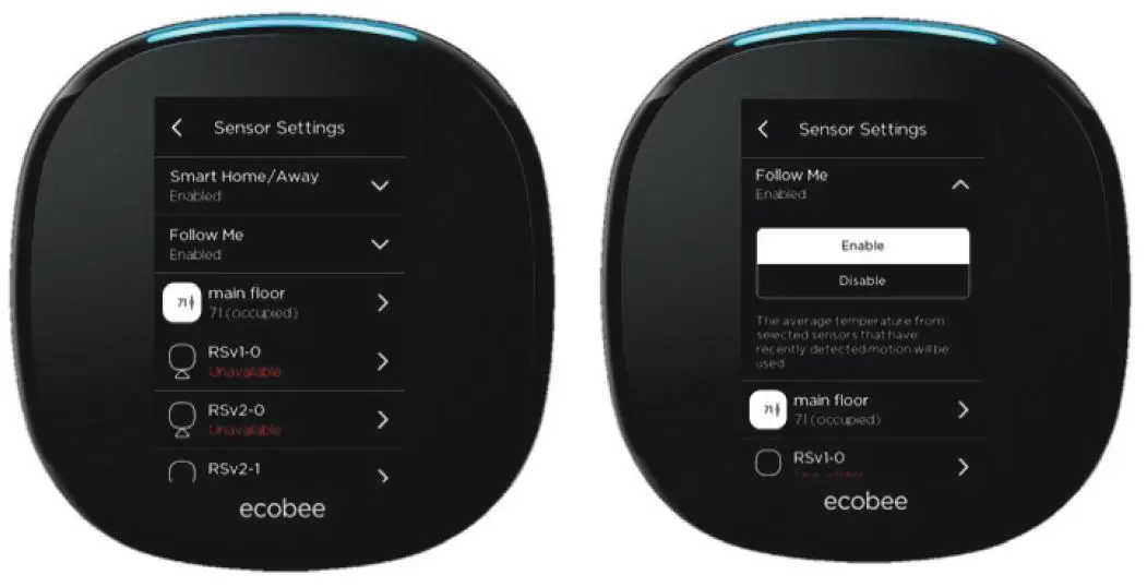
Several settings can be adjusted for the main thermostat’s sensor and the remote sensors. For users with remote sensors, the “Follow Me” feature allows sensors that have occupancy detected to become the active sensors being used. Other sensors without occupancy will be ignored. If more than one sensor detects occupancy (or, motion), they will be averaged. The ecobee thermostat makes changes gradually when multiple sensors are detecting occupancy to make sure there are no sudden changes for the heating and cooling system to deal with. Similarly, once someone leaves a room and the sensor stops detecting occupancy, the thermostat’s temperature data is gradually (and not immediately) removed from the calculation.
Each sensor can be used with a Comfort Setting (Home, Away, & Sleep). At least one sensor (or the thermostat’s internal sensor) must be selected (or, checked) per Comfort Setting. If more than one sensor is selected per Comfort Setting, then they will be averaged. If “Follow Me” is on, then only the sensors that are enabled for that Comfort Setting AND are detecting occupancy will be used. The Name of the sensor can also be adjusted.
Resources
ecobee provides multiple online resources and phone support for both homeowners and contractors. The phone numbers here are specific to the Pro thermostat models. Since all of the ecobee units are the Pro models, they all have the 5-year warranty. These Pro Support numbers are dedicated for Carrier: customer support is provided by ecobee. And as always, go to HVAC Partners and My Learning Center to learn more.
Training
My Learning Center is your central location for professional residential HVAC training resources that help strengthen careers and businesses. We believe in providing high quality learning experiences both online and in the classroom. Access My Learning Center with your HVACpartners credentials at www.mlctraining.com.
Documents / Resources
 | Carrier EB-STATE3LTCB-01 Ecobee Smart Thermostat Pro with Voice Control [pdf] Instruction Manual EB-STATE3LTCB-01, EB-STATE3LTCR-01, EB-STATE3LTCB-01 Ecobee Smart Thermostat Pro with Voice Control, EB-STATE5CB-01, EB-STATE5CR-01, Ecobee Smart Thermostat Pro with Voice Control, A200451, A200452 |


")

