![]()
![]()
DX PTG_2021 Final Power-Actuated Tool
Listings/Approvals
ICC-ES (International Code Council)
ESR-2196 with LABC/LARC Supplement (Steel and Metal Screws)
ESR-3891 with LABC/LARC Supplement
Interior Finishing/Drywall Screws
ICC-ES ESR-2196 and ESR-3891
together, provide IBC recognition of Hilti’s Self-Drilling Screw fasteners for most common applications (e.g. CFS connections, gypsum to CFS, etc.),
including HWH, HHWH, PPH, PPFH, PBH, PWH, PTH, PPCH, TPCH, and PFTH head style screws. Wood screws are not covered in the ICC-ESRs.
3.6.2 SELF-DRILLING SCREWS
PRODUCT DESCRIPTION
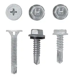
Hilti self-drilling screws are designed to drill their own hole in steel base materials up to 1/2″ thick. These screws are available in a variety of head styles, thread lengths and drill-flute lengths for screw diameters #6 through 1/4″. Hilti self-drilling screws meet ASTM C1513, ASTM C954 and SAE J78 standards, as applicable.
Product features:
- Hex head for metal-to-metal applications
- Flush head for wood-to-metal applications
- For metal from 0.035″ to 0.500″ thick
- Winged reamers for wood over 1/2″ thick
- Stitch screws for light gauge metal-to-metal
- Sealing screws for water-resistant fastenings
MATERIAL SPECIFICATIONS
| Material | ASTM A510 Grade 1018-1022 |
| Heat treatment | Case hardened and tempered • Sizes 8, 10 and 12: 0.004″ to 0.009″ case depth • Size 1/4″: 0.005″ to 0.011″ case depth |
| Plating | Refer to Section 3.6.2.5 for screw coating information. |
Warning: Because of the potential for delayed hydrogen-assisted stress corrosion cracking, many hardened steel fasteners are not recommended for use with dissimilar metals or chemically treated wood when moisture may be present or in corrosive environments. For further information, contact Hilti Technical Support at 1-877-749-6337.
TECHNICAL DATA
Ultimate tensile strengths – pullout (tension), Ib (kN)’23+5%7
| Screw designation | Nominal diameter in. | The thickness of steel member not in contact with the screw head, ga (in.) | |||||
| 20 (0.036) | 18 (0.048) | 16 (0.060) | 14 (0.075) | 12 (0.105) | 10 (0.135) | ||
| #6 | 0.138 | 190 (0.85) | 250 (1.11) | 320 (1.42) | 395 (1.76) | 555 (2.47) | 715 (3.18) |
| #7 | 0.151 | 210 (0.93) | 275 (1.22) | 345 (1.53) | 435 (1.93) | 605 (2.69) | 780 (3.47) |
| #8 | 0.164 | 225 (1.00) | 300 (1.33) | 375 (1.67) | 470 (2.09) | 660 (2.94) | 845 (3.76) |
| #10 | 0.190 | 260 (1.16) | 350 (1.56) | 435 (1.93) | 545 (2.42) | 765 (3.40) | 980 (4.36) |
| #12 | 0.216 | 295 (1.31) | 395 (1.76) | 495 (2.20) | 620 (2.76) | 870 (3.87) | 1120 (4.98) |
| 1/4 in. | 0.250 | 345 (1.53) | 460 (2.05) | 575 (2.56) | 715 (3.18) | 1000 (4.45) | 1290 (5.74) |
- The lower of the ultimate pullout, pullover, and tension fastener strength of screw should be used for design.
- Load values based upon calculations done in accordance with Section J4 of the AISI $100.
- AISI S100 recommends a safety factor of 3.0 be applied for allowable strength design, a ® factor of 0.5 be applied for LRFD design or a ® factor of 0.4 be applied for LSD design.
- ANSI/ASME standard screw diameters were used in the calculations and are listed in the tables.
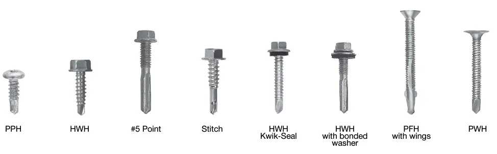
- The screw diameters in the table above are available in head styles of pan, hex washer, pancake, flat, wafer and bugle.
- The load data in the table is based upon sheet steel with F, = 45 ksi. For F, = 55 ksi steel, multiply values by 1.22. For F, = 65 ksi steel, multiply values by 1.44.
- Refer to Section 3.6.2.5 to ensure drilling capacities.
Direct Fastening Technical Guide, Edition 21
Ultimate tensile strengths — pullover (tension), Ib (kN)’?>+567
| Screw designation | Washer or head diameter in. | The thickness of steel member in contact with the screw head, ga (in.) I | ||||||
| 22 (0.030) | 20 (0.036) | 18 (0.048) | 16 (0.060) | 14 (0.075) | 12 (0.105) | 10 (0.135) | ||
Hex Washer head (HWH)
| #8 | 0.335 | 675 (3.00) | 815 (3.63) | 1000 (4.45) | 1000 (4.45) | 1000 (4.45) | 1000 (4.45) | 1000 (4.45) |
| #10 | 0.399 | 805 (3.58) | 970 (4.31) | 1290 (5.74) | 1370 (6.09) | 1370 (6.09) | 1370 (6.09) | 1370 (6.09) |
| #12-14 | 0.415 | 835 (3.71) | 1010 (4.49) | 1340 (5.96) | 1680 (7.47) | 2100 (9.34) | 2325 (10.34) | 2325 (10.34) |
| #12-24 | 0.415 | 835 (3.71) | 1010 (4.49) | 1340 (5.96) | 1680 (7.47) | 2100 (9.34) | 2940 (13.08) | 3780 (16.81) |
| 1/4 in. _ | 0.500 | 1010 (4.49) | 1220 (5.43) | 1620 (7.21) | 2030 (9.03) | 2530 (11.25) | 3540 (13.75) | 4560 (20.28) t |
Phillips Pan Head (PPH)
| #7 | 0.303 | 615 (2.74) | 735 (3.27) | 980 (4.36) | 1000 (4.45) | 1000 (4.45) | 1000 (4.45) | 1000 I (4.45) |
| #8 | 0.311 | 630 (2.80) | 755 (3.36) | 1000 (4.45) | 1000 (4.45) | 1000 (4.45) | 1000 (4.45) | 1000 (4.45) |
| #10 | 0.364 | 740 (3.29) | 885 (3.94) | 1180 (5.25) | 1370 (6.09) | 1370 (6.09) | 1370 (6.09) | 1370 (6.09) |
Phillips Truss Head (PTH)
| #8 | 0.411 | 830 (3.69) | 1000 (4.45) | 1000 (4.45) | 1000 (4.45) | 1000 (4.45) | 1000 (4.45) | 1000 (4.45) |
| #10 | 0.433 | 875 (3.89) | 1050 (4.67) | 1390 (6.18) | 1390 (6.18) | 1390 (6.18) | 1390 (6.18) | 1390 (6.18) |
Phillips Pancake Head (PPCH)
| #10, #12 | 0.409 | 830 (3.69) | 995 (4.43) | 1325 (5.89) | 1370 (6.09) | 1370 (6.09) | 1370 (6.09) | 1370 (6.09) |
| Phillips Flat Truss Head (PFTH) | ||||||||
| #10 | 0.364 | 740(3.) | 885(4.) | 1180(5.) | 1475(7.) | 1840 (8.) | 2170 (10.) | 2170 (9.65) 4 |
- The lower of the ultimate pullout, pullover, and tension fastener strength of screw should be used for design.
- Load values are based upon calculations done in accordance with Section J4 of the AISI S100.
- AISI S100 recommends a safety factor of 3.0 is applied for allowable strength design, a factor of 0.5 be applied for LRFD design or a ® factor of 0.4 be applied for LSD design.
- ANSI/ASME standard screw head diameters were used in the calculations and are listed in the tables.
- Phillips Bugle Head (PBH) and Phillips Wafer Head (PWH) styles are not covered by this table because they are not intended for the attachment of steel to steel.
- The load data in the table is based upon sheet steel with F, = 45 ksi. For F, = 55 KSI steel, multiply values by 1.22. For F, = 65 ksi steel, multiply values by 1.44.
- Refer to Section 3.6.2.5 for drilling capacities.
Nominal ultimate fastener strength of the screw
| Screw designation | Nominal diameter (in.) | Nominal fastener strength | |||
| Tension, Pts lb (kN)1 | Shear, P ss lb (kN)2,3 | ||||
| #6-20 | 0.138 | 1000 | (4.45) | 890 | (3.96) |
| #7-18 | 0.151 | 1000 | (4.45) | 890 | (3.96) |
| #8-18 | 0.164 | 1000 | (445.) | 1170 | (5.20) |
| #10-12 | 0.190 | 2170 | (10.65) | 1645 | (7.32) |
| #10-16 | 0.190 | 1370 | (6.09) | 1215 | (5.20) |
| #10-18 | 0.190 | 1390 | (6.18) | 1645 | (7.32) |
| #12-14 | 0.216 | 2325 | (10.34) | 1880 | (8.36) |
| #12-24 | 0.216 | 3900 | (17.35) | 2285 | (10.16) |
| 1/4 in. | 0.250 | 4580 | (20.37) | 2440 | (10.85) , |
- The lower of the ultimate pullout, pullover, and tension fastener strength of screw should be used for design. The Pullout and Pullover tables in this section have already been adjusted where screw strength governs.
- The lower of the ultimate shear fastener strength and shear bearing should be used for design. The Shear Bearing table in this section has already been adjusted where screw strength governs.
- AISI S100 recommends a safety factor of 3.0 be applied for allowable strength design, a ® factor of 0.5 be applied for LRFD design or a ® factor of 0.4 be applied for LSD design.
Torsional strength’1,2
| Size | Min. torsional strength in-lb (Nm) | |
| 6-20 | 24 | (2.7) |
| 7-18 | 38 | (4.3) |
| 8-18 | 42 | (5.8) |
| 10-12 | 61 | (7.9) |
| 10-16 | 61 | (6.9) |
| 10-18 | 61 | (6.9) |
| 10-24 | 65 | (6.9) |
| 12-14 | 92 | (10.) |
| 12-24 | 100 | (11.) |
| 1/4/14 | 150 | (17.) |
| 1/4/20 | 156 | (18.) |
- Based on screw only. Does not consider base material limitations.
- Values in table are ultimate torsional strengths. To obtain maximum setting torque, multiply values in table by 0.66.
Ultimate shear strengths — bearing (shear), Ib (KN)’234567
| Screw designation | Nominal diameter in. | Thickness of steel member in contact with screw head ga (in.) | Thickness of steel member not in contact with the screw head, ga (in.) | ||||||||
| 20 (0.036) | 18 (0.048) | 16 (0.060) | 14 (0.075) | ? 12 (0.105) | |||||||
| #7
| 0.151
| 20 (0.036) | 500 | (2.) | 660 | (3.) | 660 | (3.) | 660 | (3.) | 660 (2.94) |
| 18 (0.048) | 500 | (2.) | 770 | (3.) | 880 | (4.) | 880 | (4.) | 880 (3.91) | ||
| ? 16 (0.060) | 500 | (2.) | 770 | (3.) | 890 | (4.) | 890 | (4.) | 890 (3.96) | ||
| 20 (0.036) | 525 | (2.) | 715 | (3.) | 715 | (3.) | 715 | (3.) | 715 (3.18) | ||
| #8
| 0.164
| 18 (0.048) | 525 | (2.) | 805 | (4.) | 955 | (4.) | 955 | (4.) | 955 (4.25) |
| ? 16 (0.060) | 525 | (2.) | 805 | (4.) | 1120 | (5.) | 1170 | (5.) | 1170 (5.20) | ||
| 20 (0.036) | 565 | (3.) | 830 | (4.) | 830 | (4.) | 830 | (4.) | 830 (3.69) | ||
| 18 (0.048) | 565 | (3.) | 865 | (4.) | 1110 | (5.) | 1110 | (5.) | 1110 (4.94) | ||
| 16 (0.060) | 565 | (3.) | 865 | (4.) | 1210 | (5.) | 1390 | (6.) | 1390 (6.18) | ||
| ? 14 (0.075) | 565 | (3.) | 865 | (4.) | 1210 | (5.) | 1645 | (7.) | 1645 (7.32) | ||
| 20 (0.036) | 565 | (3.) | 830 | (4.) | 830 | (4.) | 830 | (4.) | 830 (3.69) | ||
| #10-16
| 0.190
| 18 (0.048) | 565 | (3.) | 865 | (4.) | 1110 | (5.) | 1110 | (5.) | 1110 (4.94) |
| 16 (0.060) | 565 | (3.) | 865 | (4.) | 1210 | (5.) | 1215 | (5.) | 1215 (5.40) | ||
| 20 (0.036) | 565 | (3.) | 830 | (4.) | 830 | (4.) | 830 | (4.) | 830 (3.69) | ||
| 18 (0.048) | 565 | (3.) | 865 | (4.) | 1110 | (5.) | 1110 | (5.) | 1110 (4.94) | ||
| 16 (0.060) | 565 | (3.) | 865 | (4.) | 1210 | (5.) | 1390 | (6.) | 1390 (6.18) | ||
| 14 (0.075) | 565 | (3.) | 865 | (4.) | 1210 | (5.) | 1645 | (7.) | 1645 (7.32) | ||
| 20 (0.036) | 600 | (3.) | 930 | (4.) | 945 | (4.) | 945 | (4.) | 945 (4.20) | ||
| 18 (0.048) | 600 | (3.) | 925 | (4.) | 1260 | (6.) | 1260 | (6.) | 1260 (5.60) | ||
| 16 (0.060) | 600 | (3.) | 925 | (4.) | 1290 | (6.) | 1570 | (7.) | 1570 (6.98) | ||
| ? 14 (0.075) | 600 | (3.) | 925 | (4.) | 1290 | (6.) | 1800 | (8.) | 1880 (8.36) | ||
| 20 (0.036) | 600 | (3.) | 930 | (4.) | 945 | (4.) | 945 | (4.) | 945 (4.20) | ||
| 18 (0.048) | 600 | (3.) | 925 | (4.) | 1260 | (6.) | 1260 | (6.) | 1260 (5.60) | ||
| #12-24
| 0.216
| 16 (0.060) | 600 | (3.) | 925 | (4.) | 1290 | (6.) | 1570 | (7.) | 1570 (6.98) |
| 14 (0.075) | 600 | (3.) | 925 | (4.) | 1290 | (6.) | 1800 | (8.) | 1970 (8.76) | ||
| ? 12 (0.090) | 600 | (3.) | 925 | (4.) | 1290 | (6.) | 1800 | (8.) | 2285 (10.16) | ||
| 20 (0.036) | 645 | (3.) | 1020 | (5.) | 1090 | (5.) | 1090 | (5.) | 1090 (4.85) | ||
| 18 (0.048) | 645 | (3.) | 995 | (4.) | 1400 | (6.) | 1460 | (6.) | 1460 (6.49) | ||
| 1/4 in.
| 0.250
| 16 (0.060) | 645 | (3.) | 995 | (4.) | 1390 | (6.) | 1820 | (8.) | 1820 (8.10) |
| 14 (0.075) | 645 | (3.) | 995 | (4.) | 1390 | (6.) | 1940 | (9.) | 2280 (10.14) | ||
| 2 12 (0.090) | 645 | (3.) | 995 | (4.) | 1390 | (6.) | 1940 | (9.) | 2440 (10.85) | ||
- The lower of the ultimate shear bearing and shear fastener strength of the screw should be used for design.
- Load values are based upon calculations done in accordance with Section J4 of AISI $100.
- AISIS100 recommends a safety factor of 3.0 be applied for allowable strength design, a © factor of 0.5 be applied for LRFD design or a ® factor of 0.4 be applied for LSD design.
- ANSI/ASME standard screw diameters were used in the calculations and are listed in the tables.
- Load values in the table are for Hex Washer Head (HWH and HHWH), Phillips Pan Head (PPH), Phillips Truss Head (PTH), Phillips Pancake Head (PPCH), and Phillips Flat Truss Head (PFTH) style screws. Phillips Bugle Head (PBH) and Phillips Wafer Head (PWH) styles are not covered by this table because they are not intended for the attachment of steel to steel.
- The load data in the table is based upon sheet steel with F, = 45 ksi. For F, = 55 ksi steel, multiply values by 1.22. For F, = 65 ksi steel, multiply values by 1.44.
- Refer to Section 3.6.2.5 to ensure drilling capacities.
INSTALLATION INSTRUCTIONS
For a general discussion of Hilti screw fastener installation, reference Section 3.6.1.7.
For allowable diaphragm shear loads and stiffness values for steel roof or floor deck utilizing Hilti self-drilling screws as frame or sidelap fasteners, reference Section 3.5 and download Hilti’s Profis DF software at www.hilti.com/decking (US), or www.hilti.ca (Canada).
To estimate the number of sidelap screws on a steel roof or floor deck project, reference Section 3.5.1.5. Warning: Because of the potential for delayed hydrogen-assisted stress corrosion cracking, many hardened steel fasteners are not recommended for use with dissimilar metals or chemically treated wood when moisture may be present or in corrosive environments. For further information, contact Hilti Technical Support at 1-877-749-6337.
ORDERING INFORMATION
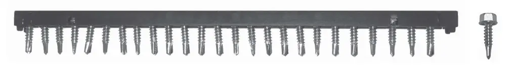 Collated self-drilling screws
Light/medium gauge metal applications (sidelap)
| Description | Thread length | Drilling Min | Capacity Max | Maximum Total Thickness (MT)’ | Recess | Coating2 | Box qty | |
| S-SLC 01 M HWH Collated | 5/8″ | 0.018″ | 0.095″ | 3/32″ | 0.100″ | 5/16″ | Zinc-2 | 250 |
| S-SLC 02 M HWH Collated | 3/4″ | 0.028″ | 0.120″ | 3/8″ | 0.375″ | 5/16″ | Zinc-1 | 250 |
| S-MD 10-16 x 7/8 HWH Collated | 3/8″ | 0.028″ | 0.120″ | 3/16″ | 0.188″ | 5/16″ | Zinc-1 | 250 |
Medium/heavy gauge metal applications (frame fastener)
| Description | Drilling Capacity | Maximum TotalThickness (MT)’ | Recess | Coating2 | Box qty | |||
| Thread length | Min | Max | ||||||
| S-SLC 01 M HWH Collated | 5/8″ | 0.018″ | 0.095″ | 3/32″ | 0.100″ | 5/16″ | Zinc-2 | 250 |
| S-SLC 02 M HWH Collated | 3/4″ | 0.028″ | 0.120″ | 3/8″ | 0.375″ | 5/16″ | Zinc-1 | 250 |
| S-MD 10-16 x 7/8 HWH Collated | 3/8″ | 0.028″ | 0.120″ | 3/16″ | 0.188″ | 5/16″ | Zinc-1 | 250 |
- Refer to Figure in Section 3.6.1.5. 2 For coating abbreviations, Zinc-1 = EN/ISO 4042 A3F; Zinc-2 = Cr3 + (Cr6 + free) 8-14 pm.
- For more information on corrosion resistance, reference Section 3.6.1.6.

Single Self-Drilling Screws
Sitemap (unsupported metal sheets)
| Description | Thread length | Drilling capacity | Maximum total thickness (MT)1 | Recess | Coating2 | Box qty | ||
| Min | Max | |||||||
| S-MD 12-14×1 HHWH Stitch | 3/4″ | 0.028″ | 0.120″ | 3/8″ | 0.375″ | 5/16″ | Zinc-1 | 3000 |
| S-MD 10-16×7/8 HHWH Pilot Point | 3/8″ | 0.028″ | 0.120″ | 3/16″ | 0.188″ | 5/16″ | Zinc-1 | 6000 |
| S-MD 1/4-14×7/8 HWH Stitch Kwik-Seal | 1/2″ | 0.028″ | 0.140″ | 5/16″ | 0.313″ | 5/16″ | Kwik-Cote | 2500 |
- Refer to Figure in Section 3.6.1.5. 2
- For coating abbreviations, Zinc-1 – ENASO 4042 A3F; Kwik Cote – Proprietary Coating, Section 3.6.2.2 For more information on corrosion resistance, reference Section 3.6.1.6.
Light gauge applications: steel to steel
| Description | Thread length | Drilling Min | Capacity Max | Maximum Total Thickness (MT)1 ea | Recess | Coating2 | Box Qty | |
| S-MD 8-18×1/2 HWH #2 | 1/4″ | 0.035″ | 0.100″ | 1/8″ | 0.125″ | 1/4″ | Zinc-1 | 1000 |
| S-MD 8-18×3/4 HWH #2 | 1/2″ | 0.035″ | 0.100″ | 3/8″ | 0.375″ | 1/4″ | Zinc-1 | 1000 |
| S-MD 8-18×1/2 PPH #2 | 1/4″ | 0.035″ | 0.100″ | 1/8″ | 0.125″ | PHL #2 | Zinc-1 | 1000 |
| S-MD 10-16×1/2 HWH #2 | 5/16″ | 0.035″ | 0.110″ | 3/16″ | 0.188″ | 5/16″ | Zinc-1 | 8500 |
| S-MD 10-16×3/4 HWH #2 | 1/2″ | 0.035″ | 0.110″ | 5/16″ | 0.313″ | 5/16″ | Zinc-1 | 6500 |
| S-MD 10-16×1 HWH #2 | 3/4″ | 0.035″ | 0.110″ | 1/2″ | 0.500″ | 5/16″ | Zinc-1 | 5000 |
- Refer to Figure in Section 3.6.1.5.
- For coating abbreviations, Zinc-1 = EN/ISO 4042 A3F For more information on corrosion resistance, reference Section 3.6.1.6.
Light/medium gauge metal applications
| Description | Thread length | Drilling Min | capacity Max | Maximum total thickness (MT)’ | Recess | Coating2 | Box Qty | |
| S-MD 10-16×5/8 HWH #3 | 5/16″ | 0.110″ | 0.175″ | 3/16″ | 0.187″ | 5/16″ | Zinc-1 | 7500 |
| S-MD 10-16×3/4 HWH #3 | 1/2″ | 0.110″ | 0.175″ | 3/8″ | 0.375″ | 5/16″ | Zinc-1 | 6500 |
| S-MD 10-16×3/4 HHWH #3 | 1/2″ | 0.110″ | 0.175″ | 3/8″ | 0.375″ | 5/16″ | Zinc-1 | 6500 |
| S-MD 10-16×1 HWH #3 | 3/4″ | 0.110″ | 0.175″ | 5/8″ | 0.625″ | 5/16″ | Zinc-1 | 5000 |
| S-MD 10-16×1 1/4 HWH #3 | 1″ | 0.110″ | 0.175″ | 7/8″ | 0.875″ | 5/16″ | Zinc-1 | 4000 |
| S-MD 10-16×1 1/2 HWH #3 | 1-1/4″ | 0.110″ | 0.175″ | 1-1/8″ | 1.125″ | 5/16″ | Zinc-1 | 4000 |
| S-MD 10-16×5/8 PPH #3 | 5/16″ | 0.110″ | 0.175″ | 5/16″ | 0.313″ | PHL #2 | Zinc-1 | 7500 |
| S-MD 10-16×3/4 PPH #3 | 1/2″ | 0.110″ | 0.175″ | 3/8″ | 0.375″ | PHL #2 | Zinc-1 | 6500 |
| S-DD 10-16×5/8 PPCH #3 | 1/2″ | 0.110″ | 0.175″ | 5/16″ | 0.313″ | PHL #2 | Zinc-1 | 7500 |
| S-DD 10-12×3/4 PFTH #3 | 9/16″ | 0.110″ | 0.175″ | 3/8″ | 0.375″ | PHL #2 | Zinc-1 | 7500 |
| S-DD 10-18×3/4 PTH #3 | 9/16″ | 0.110″ | 0.175″ | 3/8″ | 0.375″ | PHL #2 | Zinc-1 | 5000 |
| S-MD 12-14×3/4 HWH #3 | 1/2″ | 0.110″ | 0.210″ | 5/16″ | 0.313″ | 5/16″ | Zinc-1 | 5000 |
| S-MD 12-14×1 HWH #3 | 3/4″ | 0.110″ | 0.210″ | 9/16″ | 0.562″ | 5/16″ | Zinc-1 | 3000 |
| S-MD 12-14×1 1/2 HWH #3 | 1-1/4″ | 0.110″ | 0.210″ | 1-1/16″ | 1.062″ | 5/16″ | Zinc-1 | 2500 |
| S-MD 12-14×2 HWH #3 | 1-5/8″ | 0.110″ | 0.210″ | 1-9/16″ | 1.562″ | 5/16″ | Zinc-1 | 2000 |
| S-DD 12-14×1 TPCH #3 | 11/16″ | 0.110″ | 0.210″ | 1/2″ | 0.500″ | TX 25 HF | Zinc-2 | 7500 |
| S-MD 1/4-14×3/4 HWH #3 | 1/2″ | 0.110″ | 0.220″ | 5/16″ | 0.313″ | 3/8″ | Zinc-1 | 4000 |
| S-MD 1/4-14×1 HWH #3 | 3/4″ | 0.110″ | 0.220″ | 9/16″ | 0.562″ | 3/8″ | Zinc-1 | 3000 |
| S-MD 1/4-14×1 1/2 HWH #3 | 1-1/4″ | 0.110″ | 0.220″ | 1-1/16″ | 1.062″ | 3/8″ | Zinc-1 | 2000 |
| S-MD 1/4-14×2 HWH #3 | 1-5/8″ | 0.110″ | 0.220″ | 1-9/16″ | 1.562″ | 3/8″ | Zinc-1 | 1000 |
| S-MD 12-14×3/4 HWH #3 Kwik-Seal | 1/4″ | 0.110″ | 0.210″ | 1/8″ | 0.125″ | 5/16″ | Kwik-Cote | 3000 |
| S-MD 12-14×1 HWH #3 Kwik-Seal | 5/8″ | 0.110″ | 0.210″ | 3/8″ | 0.375″ | 5/16″ | Kwik-Cote | 2500 |
| S-MD 12-14×1 1/4 HWH #3 Kwik-Seal | 0.110″ | 0.210″ | 5/8″ | 0.625″ | 5/16″ | Kwik-Cote | 2000 | |
| S-MD 12-14×1 1/2 HWH #3 Kwik-Seal | 1-1/4″ | 0.110″ | 0.210″ | 7/8″ | 0.875″ | 5/16″ | Kwik-Cote | 2000 |
| S-MD 12-14×2 HWH #3 Kwik-Seal | 1-1/2″ | 0.110″ | 0.210″ | 1-3/8″ | 1.375″ | 5/16″ | Kwik-Cote | 1500 |
| S-MD 1/4-14×1 HWH #3 Kwik-Seal | 5/8″ | 0.110″ | 0.220″ | 3/8″ | 0.375″ | 3/8″ | Kwik-Cote | 2000 |
| S-MD 1/4-14×1 1/2 HWH #3 Kwik-Seal | 1″ | 0.110″ | 0.220″ | 7/8″ | 0.875″ | 3/8″ | Kwik-Cote | 1500 |
- Refer to Figure in Section 3.6.1.5.
- For coating abbreviations, Zinc-1 = EN/ISO 4042 A3F; Zinc-2 = Cr3+ (Cr6+ free) 8-14 ym, Kwik-Cote = Proprietary Coating, Section 3.6.2.2. For more information on corrosion resistance,
reference Section 3.6.1.6.
Warning: Because of the potential for delayed hydrogen-assisted stress corrosion cracking, many hardened steel fasteners are not recommended for use with dissimilar metals or chemically treated wood when moisture may be present or in corrosive environments. For further information, contact Hilti Technical Support at 1-877-749-6337.
Single self-drilling screws – heavy gauge metal applications
| Description | Thread length | Drilling Min | capacity Max | Maximum total thickness (MT)1 | Recess | Coating2 | Box Qty | |
| S-MD 12-24×7/8 HWH #4 | 1/2″ | 0.175″ | 0.250″ | 1/4″ | 0.250″ | 5/16″ | Zinc-1 | 4500 |
| S-MD 12-24×1 1/4 HWH #4 | 3/4″ | 0.175″ | 0.250″ | 5/8″ | 0.625″ | 5/16″ | Zinc-1 | 3500 |
| S-MD 12-24×1 1/4 HWH #5 | 1/2″ | 0.250″ | 0.500″ | 7/16″ | 0.437″ | 5/16″ | Zinc-1 | 4000 |
| S-MD 12-24×1 1/4 HWH #5 Kwik-Cote | 1/2″ | 0.250″ | 0.500″ | 5/16″ | 0.313″ | 5/16″ | KwikCote | 4000 |
| S-MD 12-24×2 HWH #5 Kwik-Cote | 1-1/4″ | 0.250″ | 0.500″ | 1-3/16″ | 1.187″ | 5/16″ | KwikCote | 2000 |
| S-MD 12-24×3 HWH #5 Kwik-Cote | 2-1/4″ | 0.250″ | 0.500″ | 2-3/16″ | 2.187″ | 5/16″ | Kwikset | 1000 |
| S-MD 12-24×1 1/4 HWH #5 Kwik-Cote Bond Washer | 1/2″ | 0.250″ | 0.500″ | 5/16″ | 0.313 | 5/16″ | Kwikset | 2500 |
- Refer to Figure in Section 3.6.1.5.
- For coating abbreviations, Zinc-1 = EN/ISO 4042 A3F; Kwik Cote = Proprietary Coating, Section 3.6.2.2. For more information on corrosion resistance, reference
Section 3.6.1.6.
Single self-drilling screws – heavy gauge metal applications
| Description | Thread length | Drilling Min | capacity Max | Maximum total thickness (MT)1 | Recess | Coating2 | Box Qty | |
| Wood Drill Screws | ||||||||
| Decking Screws (Plywood to Framing) | ||||||||
| S-WD 8-18×1 5/16 PFH #3 | 1/2″ | 0.050″ | 0.140″ | 1/2″ | 0.500″ | PHL #2 | BP | 6000 |
| S-WD 8-18×1 15/16 PFH #3 | 5/8″ | 0.050″ | 0.140″ | 3/4″ | 0.750″ | PHL #2 | BP | 4000 |
| S-WD 10-24×1 PWH #3 | 3/4″ | 0.050″ | 0.175″ | 5/8″ | 0.625″ | PHL #2 | Zinc-1 | 6000 |
| S-WD 10-24×1 1/4 PWH #3 | 1″ | 0.050″ | 0.175″ | 7/8″ | 0.875″ | PHL #2 | Zinc-1 | 5000 |
| S-WD 10-24×1 1/2PWH #3 | 1-1/4″ | 0.050″ | 0.175″ | 1-1/8″ | 1.125″ | PHL #2 | Zinc-1 | 3500 |
| Winged Reamer Wood Drill Screws | ||||||||
| S-WW 10-24×1 7/16 PWH #3 wings | 1″ | 0.050″ | 0.175″ | 3/4″ | 0.750″ | PHL #2 | Zinc-1 | 4000 |
| S-WW 12-24×2 PFH #4 wings | 1-3/8″ | 0.050″ | 0.232″ | 1-1/4″ | 1.250″ | PHL #2 | Zinc-1 | 2000 |
| S-WW 12-24×2 1/2 PFH #4 wings | 2″ | 0.050″ | 0.232″ | 1-3/4″ | 1.750″ | PHL #2 | Zinc-1 | 1500 |
| S-WW 14-20×2 3/4 PFH #4 wings | 2-1/4″ | 0.050″ | 0.250″ | 2″ | 2.000″ | PHL #2 | Zinc-1 | 1000 |
- Refer to Figure in Section 3.6.1.5.
- For coating abbreviations, Zinc-1 = ENASO 4042 A3F; GP = Grey Phosphate. For more information on corrosion resistance, reference Section 3.6.1.6.
Warning: Because of the potential for delayed hydrogen-assisted stress corrosion cracking, many hardened steel fasteners are not recommended for use with dissimilar metals or chemically treated wood when moisture may be present or in corrosive environments. For further information, contact Hilti Technical Support at 1-877-749-6337.
Drywall applications (drywall to steel, framing and lathing screws)
| Description | Coating’ | Box qty | Application |
| 6 x 1 PBH SD2 | DGP | 10,000 | Fastening Drywall, plywood, insulation, etc. to metal studs from 14 ga to 20 ga |
| 6 x 1 PBH SD Z2 | Zinc | 10,000 | |
| 6 x 1-1/8 PBH SD2 | DGP | 10,000 | |
| 6 x 1-1/8 PBH SD r | Zinc | 10,000 | |
| 6 x 1-1/4 PBH SD2 | DGP | 8,000 | |
| 6 x 1-1/4 PBH SD V | Zinc | 8,000 | |
| 6 x 1-1/4 PBH SD CRC2 | CRC | 8,000 | |
| 6 x 1-5/8 PBH SD2 | DGP | 5,000 | |
| 6 x 1-5/8 PBH SD Z2 | Zinc | 5,000 | |
| 6 x 1-7/8 PBH SD2 | DGP | 4,000 | |
| 6 x 1-7/8 PBH SD Z2 | Zinc | 4,000 | |
| 6 x 1-7/8 PBH SD CRC2 | CRC | 4,000 | |
| 6 x 2 PBH SD2 | GP/DGP | 4,000 | |
| 6 x 2 PBH SD Z2 | Zinc | 4,000 | |
| 8 x 2-3/8 PBH SD | GP | 2,500 | |
| 8 x 2-3/8 PBH SD zinc | Zinc | 2,500 | |
| 8 x 2-5/8 PBH SD | GP | 1,600 | |
| 8 x 2-5/8 PBH SD zinc | Zinc | 1,600 | |
| 8 x 3 PBH SD | GP | 1,400 | |
| 8 x 3 PBH SD zinc | Zinc | 1,400 | |
| 7 x 7/16 PPFH SD Framer | GP | 10,000 | Fastening stud to track from 14 ga to 20 ga |
| 7 x 7/16 PPFH SD Farmer Zinc | Zinc | 10,000 | |
| 8 x 1/2 PPH SD Framer Zinc | Zinc | 10,000 | |
| 10 x 5/8 PPCH SD Framer | Zinc | 7,500 | |
| 10 x 3/4 PFTH SD Framer Zinc | Zinc | 7,500 | |
| 10 x 3/4 PTH SD Framer Zinc | Zinc | 5,000 | |
| 8 x 1/2 PTH SD Lathing Zinc | Zinc | 10,000 | Fastening wire lath to 14 ga to 20 ga |
| 8 x 3/4 PTH SD Lathing Zinc | Zinc | 10,000 | |
| 8 x 1 PTH SD Lathing Zinc | Zinc | 8,000 | |
| 8 x 1-1/4 PTH SD Lathing Zinc | Zinc | 8,000 | |
| 6 x 1-5/8 SFH SD | DGP | 5,000 | Fastening wood trim and base to 14 ga to 20 ga studs |
| 6 x 2-1/4 SFH SD Zinc | Zinc | 3,000 |
- For coating abbreviations, GP = Grey phosphate per EN ISO 3892; DGP = Dark Grey phosphate per EN ISO 3892; Zinc = electroplated zinc coating; CRC = Proprietary Duplex Coating. For more information on corrosion resistance, reference Section 3.6.1.6.
- Available in both single screw and collated screws.
The importance of IBC-compliant screws.
![]() ICC-ES ESR-2196 (Steel and Metal screw report) and ESR-3891 (Interior Finish/Drywall screw report) provide IBC recognition of Hilti’s Self-Drilling Screw Fasteners. This recognition was based on a comprehensive and rigorous independent evaluation of Hilti’s Self-Drilling Screw Fasteners to the latest IBC code requirements in ICC-ES AC118 Acceptance Criteria for Self-Tapping Screw Fasteners, as well as the AISI S904 and AISI S905 test standards. AC118 provides the IBC code recognition and quality assurance for screw fasteners. ICC-ES ESR-2196 recognizes Steel and Metal Hilti screws which are used to connect cold-formed steel members together. ICC-ES ESR-3891 recognizes Interior Finish/ Drywall screws which are used to connect gypsum board materials to cold-formed steel base material cover the HWH, HHWH, PPH, PPFH, PBH, PWH, PTH, PPCH, TPCH and PFTH head style Hilti screws. To ensure IBC compliance of screws on your next project, reference ESR-2196 and ESR-3891.
ICC-ES ESR-2196 (Steel and Metal screw report) and ESR-3891 (Interior Finish/Drywall screw report) provide IBC recognition of Hilti’s Self-Drilling Screw Fasteners. This recognition was based on a comprehensive and rigorous independent evaluation of Hilti’s Self-Drilling Screw Fasteners to the latest IBC code requirements in ICC-ES AC118 Acceptance Criteria for Self-Tapping Screw Fasteners, as well as the AISI S904 and AISI S905 test standards. AC118 provides the IBC code recognition and quality assurance for screw fasteners. ICC-ES ESR-2196 recognizes Steel and Metal Hilti screws which are used to connect cold-formed steel members together. ICC-ES ESR-3891 recognizes Interior Finish/ Drywall screws which are used to connect gypsum board materials to cold-formed steel base material cover the HWH, HHWH, PPH, PPFH, PBH, PWH, PTH, PPCH, TPCH and PFTH head style Hilti screws. To ensure IBC compliance of screws on your next project, reference ESR-2196 and ESR-3891.
The following pages are an excerpt from the North American Product Technical Guide, Volume 1: Direct Fastening Technical Guide, Edition 21. Please refer to the publication in its entirety for complete details on this product including data development, base materials, general suitability, installation, corrosion, and product specifications.
Direct Fastening Technical Guide, Edition 21
To consult directly with a team member regarding our direct fastening products, contact Hilti’s team of technical support specialists between
the hours of 7:00am – 5:00pm CST.
US: 877-749-6337 or [email protected]
CA: 1-800-363-4458 ext. 6 or [email protected]


