Z-Wave Ring Alarm Glass Break Sensor
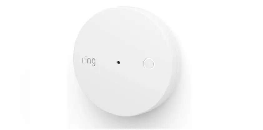
Ring Glass Break Sensor
The Ring Glass Break Sensor is a device that can be added to your Ring Alarm system to detect the sound of breaking glass. It is designed to be installed on walls, ceilings, or shelves near glass windows and doors.
Installation
- Choose a suitable location on a wall, ceiling, or shelf for installing the Glass Break Sensor.
- Ensure that the installation surfaces are clean and free from dust or dirt.
- Peel the backing of the double-sided tape provided and attach the sensor to a location within 25 feet (7.62m) of your glass windows and doors.
Z-Wave Instructions
The Ring Glass Break Sensor can be added to a Z-Wave network using Smart Start or Classic inclusion mode.
Smart Start Inclusion Steps
- In the Ring app, tap Set Up a Device > Security > Sensors and follow the in-app instructions to find the Glass Break Sensor.
- Scan the QR code found on the package or on the device itself when prompted by the mobile application.
- Pull the pull-tab or insert batteries to power on the device and enter Smart Start inclusion mode.
Classic Inclusion Steps
- In the Ring app, select add manually and enter the 5-digit DSK pin found on the package or under the QR code on the device.
- Power on the device and press and hold the setup button on the front for 3 seconds. Release the button to enter Classic inclusion mode.
LED Behavior for Inclusion
- Smart Start Started: Green LED blinks quickly, repeated after a brief pause.
- Classic Inclusion Started: Green LED blinks quickly, repeated after a brief pause.
- Classic Inclusion Timed-Out: Alternate red and green LED blinks a few times.
- Inclusion Successful (Authenticated S2): Green LED stays on solid.
- Inclusion Not Successful (Self-Destruct): Red LED stays on solid.
Removing a Sensor from a Z-Wave Network
To remove the Glass Break Sensor from a Z-Wave network, follow these steps:
- Put the Z-Wave controller in Remove (Z-Wave Exclusion) mode.
- Use a paper clip or similar object to tap the pinhole button on the device. The red LED will turn on solid to indicate successful removal from the network.
Factory Default Instructions
To restore the Glass Break Sensor to factory default settings, follow these steps:
- Locate the pinhole reset button inside the battery compartment on the back of the device after removing the mounting bracket.
- Insert a paperclip or similar object into the pinhole and press and hold the button down for 10 seconds.
- The device will rapidly blink green continuously for 10 seconds. When the green blinking stops, release the button. The red LED will turn on solid to indicate successful removal from the network.
Note: Use the factory default instructions only when the network primary controller is missing or inoperable.
Ring Glass Break Sensor
Introduction
Ring Alarm Glass Break Sensor is a wireless sensor for the Ring Alarm system which provides users the ability to know when breaking glass is detected. After installing the sensor on a wall, ceiling or shelf and setting up the sensor in the Ring app, monitor and receive notifications when breaking glass is detected. The Ring Alarm Base Station is required to enable Glass Break Sensor features and functions within the Ring app.
Note
- This product can be operated in any Z-Wave™ network with other Z-Wave certified devices from other manufacturers. All mains operated nodes within the network will act as repeaters regardless of vendor to increase reliability of the network.
- SmartArt enabled products can be added into a Z-Wave network by scanning the Z-Wave QR Code present on the product with a controller providing SmartStart inclusion. No further action is required and the SmartStart product will be added automatically within 10 minutes of being switched on in the network vicinity.
Ring Glass Break Sensor – Basic Setup & Installation
- Ensure your Ring Alarm system is disarmed.
- In the Ring app, tap Set Up a Device > Security > Sensors to find the Glass Break Sensor
- Follow the in-app instructions to complete setup.
Installation
- Choose a wall or ceiling or shelf for installing your Glass Break Sensor.
- Ensure the surfaces where you plan to install your sensor are clean and free from dust or dirt.
- Using the provided double-sided tape, peel the backing and attach the sensor to the mounting location.
Note
- It is recommended to mount the Glass Break Sensor at least 7’ (2m) off the ground, and within 25 feet (7.62m) of your glass windows and doors.
Z-Wave Instructions
- Z-Wave Device Type: Notification Sensor
- Role Type: Listening Sleeping Slave (LSS)
- GENERIC_TYPE_SENSOR_NOTIFICATION (0x07)
- SPECIFIC_TYPE_NOTIFICATION_SENSOR (0x01)
Z-Wave Long Range
This device supports both Classic Z-Wave and Z-Wave Long Range. Z-Wave Long Range capable controllers can include this device as a device in the network. Long range mode allows for a much greater operating range of the device. The device can only operate in one mode at a time, and it is dictated during the inclusion process by the controller or Base Station. To change operating modes (Z-Wave SmartStart vs. Z-Wave Long Range SmartStart), the device must be removed from the network and then re-added in the desired mode.
Adding Ring Glass Break Sensor to a Z-Wave Network
Ring Glass Break Sensor can be added via Smart Start or Classic inclusion mode.
Note: When prompted for the QR Code or PIN, you may find them on the device, on the box, or on a card inside the box. Keep the device nearby. You’ll be prompted to pull the battery tab to power on the device and enter setup mode.
Smart Start Inclusion Steps
- Initiate the add flow for Security Devices in the Ring mobile application – Follow the guided add flow instructions provided in the Ring mobile application.
- When prompted by the mobile application, scan the QR code found on the package of the Glass Break Sensor. The QR code can also be found on the device itself.
- Pull the pull-tab or insert batteries, and the device will go into SmartStart inclusion mode. While in this mode, Glass Break Sensor can be added to a Z-Wave controller that supports SmartStart. SmartStart can be restarted by tapping the button on the front of the device.
Classic Inclusion Steps
- Initiate add flow for Security Devices in the Ring mobile application
- Follow the guided add flow instructions provided in the Ring mobile application.
- Select add manually and enter the 5-digit DSK pin found on the package of the Ring Alarm Glass Break Sensor or the 5-digit DSK pin found under the QR code on the device.
- After powering on the device, press and hold the setup button on the front for 3 seconds. Release the button and the device will enter Classic inclusion mode.
| LED Behavior for Inclusion | Blink Pattern |
| Smart Start Started | Green LED blink quickly, repeated after a brief pause |
| Classic Inclusion Started | Green LED blink quickly, repeated after a brief pause |
| Classic Inclusion Timed-Out | Alternate red and green a few times |
| Inclusion Successful (Authenticated S2) | Green LED on solid |
| Inclusion Not Successful (Self-Destruct) | Red LED on solid |
Removing a Sensor from a Z-Wave Network
Exclusion Instructions
- Initiate remove “Ring Alarm Glass Break Sensor” flow in the Ring Alarm mobile application
- Select the settings icon from device details page and choose “Remove Device” to remove the device. This will place the controller into Remove or “Z-Wave Exclusion” mode.
- With the controller in Remove (Z-Wave Exclusion) mode, use a paper clip or similar object and tap the pinhole button. The device’s red LED turns on solid to indicate the device was removed from the network.
Ring Alarm Glass Break Sensor – Factory Reset
Factory Default Instructions
- To restore Ring Alarm Glass Break Sensor to factory default settings, locate the pinhole reset button on the device. This is found inside the battery compartment on the back of the device after removing the mounting bracket.
- Using a paperclip or similar object, insert it into the pinhole, press and hold the button down for 10 seconds.
- The device will rapidly blink green continuously for 10 seconds. After about 10 seconds, when the green blinking stops, release the button. The red LED will turn on solid to indicate the device was removed from the network.
Note: Use this procedure only in the event that the network primary controller is missing or otherwise inoperable.
Identify Function
A controller application can send an Indicator command class with the Indicator ID 0x50 (identify) to turn on the LED on the device.
Comm Test / Manual Wake Up
- A comm test can be triggered by press the button on the front of the device.
- This will cause the device to send a Comm test Notification.
- A solid Green LED indicates a successful comm test.
- Cause the device to wake up and send a Wake Up Notification.
- A solid Green LED indicates a successful comm test.
Z-Wave Command Classes
| Command Class | Version | Required Security Class |
| Association | 2 | Highest granted |
| Association Group Information | 3 | Highest granted |
| Device Reset Locally | 1 | Highest granted |
| Firmware Update Meta Data | 5 | Highest granted |
| Indicator | 3 | Highest granted |
| Manufacturer Specific | 2 | Highest granted |
| Multi-Channel Association | 3 | Highest granted |
| Powerlevel | 1 | Highest granted |
| Security 2 | 1 | None |
| Supervision | 1 | None |
| Transport Service | 2 | None |
| Version | 3 | Highest granted |
| Z-Wave Plus Info | 2 | None |
| Notification | 8 | Highest granted |
| Wake Up | 2 | Highest granted |
| Configuration | 4 | Highest granted |
| Battery | 2 | Highest granted |
Association Command Class
| Group Identifier | Max Nodes | Description |
| 1 (Lifeline) | 0x05 |
|
Configuration Command Class
The sensor has the following supported configuration parameters.
| Parameter No. | Description | Number of Bytes | Default | Min | Max | Format |
| 1 | Heartbeats: This parameter is the number minutes between heartbeats. Heartbeats are automatic battery reports on a timer after the last event. | 1 | 70 (0x46) | 1 (0x01) | 70 (0x46) | 0x01 Unsigned |
| 2 | Number of application level retries at- tempted for messages either not ACKed or messages encapsulated via supervision get that did not receive a report. | 1 | 1 (0x01) | 0 (0x00) | 5 (0x05) | 0x01 Unsigned |
| 3 | Application Level Retry Base Wait Time Period: The number base seconds used in the calculation for sleeping between retry messages. | 1 | 5 (0x05) | 1 (0x01) | 60 (0x3C) | 0x01 Unsigned |
| 4 | Low Battery Threshold (percentage) – Once the battery crosses this threshold, it will last for 2 weeks | 1 | 25 | 0 | 100 | 0x01 Unsigned |
| 5 | Critical Battery Threshold (percentage) – Once the battery crosses this threshold, it will last for 1 week | 1 | 10 | 0 | 100 | 0x01 Unsigned |
| 6 | The number of milliseconds waiting for a Supervisory Report response to a Supervisory Get encapsulated command from the sensor before attempting a retry. | 2 | 10000 (0x2710) | 500 (0x1F4) | 30000 (0x7530) | 0x01 Unsigned |
| 7 | Z-Wave Sleep Timeout (secs): Stay awake time after last comms with hub | 1 | 10 | 0 | 15 | 0x01 Unsigned |
| 8 | Glass break Clear delay (in seconds) | 1 | 15 | 5 | 255 | 0x01 Unsigned |
| 9 | Faults within clear delay flag | 1 | 0 | 0 | 1 | 0x01 Unsigned |
| 10 | Enable LED | 1 | 1 | 0 | 1 | 0x01 Unsigned |
| 11 | Enable detection | 1 | 0 | 0 | 1 | 0x01 Unsigned |
| 12 | SPL Range Optimization | 1 | 9 | 0 | 15 | 0x01 Unsigned |
| 13 | Minimum mic SPL, part 1 | 1 | 0 | 0 | 7 | 0x01 Unsigned |
| 14 | Minimum mic SPL, part 2 | 1 | 1 | 0 | 7 | 0x01 Unsigned |
| 15 | Automatic Gain Control | 1 | 0 | 0 | 3 | 0x01 Unsigned |
| 16 | Minimum detection SPL | 1 | 4 | 0 | 7 | 0x01 Unsigned |
| 17 | Mic-OFF time | 1 | 6 | 0 | 7 | 0x01 Unsigned |
| 18 | DNN Queue size | 1 | 9 | 0 | 63 | 0x01 Unsigned |
| Parameter No. | Description | Number of Bytes | Default | Min | Max | Format |
| 19 | DNN Window | 1 | 6 | 0 | 255 | 0x01 Unsigned |
| 20 | DNN Backoff | 1 | 55 | 0 | 255 | 0x01 Unsigned |
| 21 | DNN Decision threshold | 2 | 32112 | 0 | 65535 | 0x01 Unsigned |
| 22 | Debug NDR error | 2 | 0 | 0 | 65535 | 0x01 Unsigned |
Notification Command Class, V8
| Sensor Condition | Command Class and Value Notification Report | Association Group |
| Glass Break detected |
| 1 (Lifeline) |
| Glass Break cleared |
| 1 (Lifeline) |
| Tampered |
| 1 (Lifeline) |
| Tamper Cleared |
| 1 (Lifeline) |
| Comm Test Button Pressed | Notification Report Type: System 0x09 Event: Heartbeat 0x05 | 1 (Lifeline) |
| Watchdog Notification |
| 1 (Lifeline) |
| Watchdog Notification – Tx Manager |
| 1 (Lifeline) |
| Software Fault (Ring) |
| 1 (Lifeline) |
| Software Fault (SDK) |
| 1 (Lifeline) |
| Software Reset (Not triggered by failure) |
| 1 (Lifeline) |
| Power On Reset | Notification Report
| 1 (Lifeline) |
| Sensor Condition | Command Class and Value Notification Report | Association Group |
| Brownout | Notification Report Type: 0x08 Power Management Event: 0x05 Voltage Drop/Drift | 1 (Lifeline) |
| Pin Reset (soft reset) |
| 1 (Lifeline) |
| Dropped Frame |
| 1 (Lifeline) |
| Co-Processor Watchdog |
| 1 (Lifeline) |
| Co-processor Version Fail |
| 1 (Lifeline) |
| Co-processor OTA Fail |
| 1 (Lifeline) |
To review your warranty coverage, please visit www.ring.com/warranty.
© 2023 Ring LLC or its affiliates.
Ring, Always Home, and all related logos are trademarks of Ring LLC or its affiliates.


