![]()
Smart Power Transformer
Low Voltage Zoned Transformer for
ColorLogic® and CrystaLogic™ Lights
 Owner’s Manual
LTSUY11300
Hayward Industries
400 Connell Drive, Suite 6100
Berkeley Heights, NJ 07922
Phone: (908) 355-7995
www.hayward.com
IMPORTANT SAFETY INSTRUCTIONS
When using this electrical equipment, basic safety precautions should always be followed, including the following:
![]() READ AND FOLLOW ALL INSTRUCTIONS
READ AND FOLLOW ALL INSTRUCTIONS![]() WARNING – Read and follow all instructions in this owner’s manual and on the equipment. Failure to follow instructions can cause severe injury and/or death.
WARNING – Read and follow all instructions in this owner’s manual and on the equipment. Failure to follow instructions can cause severe injury and/or death.![]() WARNING – This product should be installed and serviced only by a qualified professional.
WARNING – This product should be installed and serviced only by a qualified professional.![]() CAUTION – All electrical wiring MUST be in conformance with all applicable local codes, regulations, and the National Electrical Code (NEC).
CAUTION – All electrical wiring MUST be in conformance with all applicable local codes, regulations, and the National Electrical Code (NEC).![]()
![]() WARNING – Risk of Electric Shock. All electrical wiring MUST be in conformance with all applicable local codes, regulations, and the National Electrical Code (NEC). Hazardous voltage can shock, burn, and cause death or serious property damage. To reduce the risk of electric shock, do NOT use an extension cord to connect unit to electric supply.
WARNING – Risk of Electric Shock. All electrical wiring MUST be in conformance with all applicable local codes, regulations, and the National Electrical Code (NEC). Hazardous voltage can shock, burn, and cause death or serious property damage. To reduce the risk of electric shock, do NOT use an extension cord to connect unit to electric supply.![]() WARNING – An equipment grounding terminal is provided in the field wiring compartment. To reduce the risk of electric shock, this terminal must be connected to the grounding means provided in the electric supply panel with a conductor equivalent in size to the circuit conductors supplying this equipment.
WARNING – An equipment grounding terminal is provided in the field wiring compartment. To reduce the risk of electric shock, this terminal must be connected to the grounding means provided in the electric supply panel with a conductor equivalent in size to the circuit conductors supplying this equipment.
IMPORTANT – Reference NEC codes for all wiring standards including, but not limited to, grounding, bonding and other general wiring procedures.![]() WARNING – Networked ColorLogic Lights and related electrical connections are receiving electrical power at all times, even when the lights are OFF! Turn off power at the main breaker before servicing ColorLogic lights.
WARNING – Networked ColorLogic Lights and related electrical connections are receiving electrical power at all times, even when the lights are OFF! Turn off power at the main breaker before servicing ColorLogic lights.
SAVE THESE INSTRUCTIONS
Introduction
The Hayward® LTSUY11300 Smart Power Transformer is a 300W low voltage zoned transformer for use with ColorLogic and CrystaLogic lights. It features 4 low voltage output connections and communicates with a Hayward Omni automation device to control 4 separate zones.
Specifications
| Enclosure Size: | 9” (22.86 cm) high x 5 1/2” (13.97 cm) wide x 4 3/4” (12.065 cm) deep. Mounting brackets top and bottom |
| Enclosure Type: | (A) 0.054” corrosion resistant steel with electrostatically applied Chinchilla coating |
| Knockouts: | Total of thirteen 1/2″ – 1″ knockouts: (6) bottom, (4) right side, (3) left side |
| Electrical: | Input: 120v, 60Hz, 3A max. Output: 14 Vac @ 300W max, 75W per zone Comm: Outdoor rated 24AWG three conductor cable For field connections, use wires suitable for at least 90ºC (194ºF) |
| Circuit Protection: | A “Split Bobbin” between the primary and secondary windings assures safe operation and the built-in circuit protection will disconnect power to the transformer in case of defect or overload. This transformer is suitable for direct connection to underwater Pool and Spa lights when used with adapter, clamp and duct seal. |
Compatibility
The Smart Power Transformer is compatible with all Hayward 14V light models. When deciding the number of lights to connect to the transformer, note that the maximum power output to the 4 zones should not exceed 80% of the maximum wattage of the Smart Power Transformer (300W). In addition, the load from the lights on each individual zone should not exceed 75W. Refer to your lights manual for wattage information.
Installation
Safety Requirements
- For direct wiring of underwater lights, the installation must comply with provisions of the National Electric Code, ANSI/NFPA 70, including those in Article 680 – Swimming Pools, Fountains, and Similar Installation, or articles 68-060, 062 and 066 of the Canadian Electric Code
- The enclosure of the transformer must be provided with a fail-proof ground as required by NEC, Article 680 and any applicable local codes. For Canadian installations, the supply circuit must be protected by a ground fault circuit interrupter.
- Be sure to run the branch circuit grounding conductor to the equipment grounding conductor terminal of the panel board and that this terminal must be directly connected to the panel board enclosure.
- Because the SmartPower Transformer is supplied with a xx foot length of communication cable that must connect to the Omni control, find a suitable mounting location that is within reach. The transformer should be mounted at least 1 foot above the deck level with the field wiring compartment down and at least 4 feet (1.2m) away from the inside wall of the pool.
- Use the appropriate size waterproof fitting and duct seal to connect the conduit from the pool/ spa light to the transformer.
- All unused openings in the transformer must be closed with acceptable plugs.
- Install to permit access for servicing.
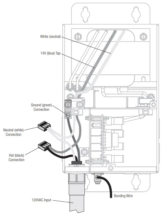
High Voltage Wiring
Unlike conventional transformers, the Smart Power Transformer requires a constant 120 VAC, 60Hz input power from a service panel (do not use a control relay). Turning the lights on/off is controlled by RS-485 communication from the Omni control. Use the blue and white conductors when wiring input power. A grounding lug is also provided. Refer to the diagram below.
Note that if you are replacing an existing transformer that is wired to a relay, the wire should be moved to the service panel to allow for a constant 120 VAC, 60Hz input power to the transformer.
Low Voltage Wiring
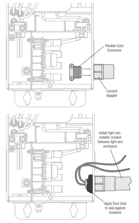
Connecting Directly to Light
When making a direct connection between the Smart Power Transformer and the low voltage light, use the included nonmetallic conduit adapter and duct seal, if necessary. Be sure to follow all local and NEC codes.
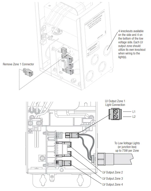
Output Wiring To Light
Disconnect the green 2 pin connector from one of the four low voltage output zones and connect the two leads from the light (or junction box) as shown below.
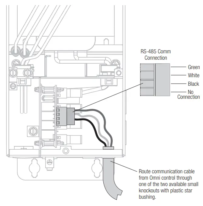
Communication Wiring at Transformer
In order to control lights with the Smart Power Transformer, communication with an Omni automation control is required. Refer to the diagram below when wiring the Smart Power to an Omni control. The SmartPower Transformer is supplied with a xx foot length of communication cable that will connect to the Omni control.
NOTE: When wiring to the Omni Control, the Smart Power Transformer will connect to the same 4-pin low speed communication bus as other Hayward Smart devices. If using multiple Smart Power Transformers, they can be daisy chained by following the color codes (green to green, white to white, etc.). After all connections are made, run a connection from one of the Smart Power Transformers to the Omni control.
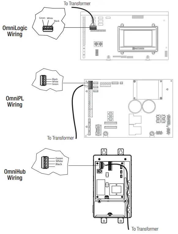
Communication Wiring at Omni Control
The Smart Power Transformer will connect to the same 4-pin low speed communication bus as other Hayward Smart Devices. Refer to the graphics below.
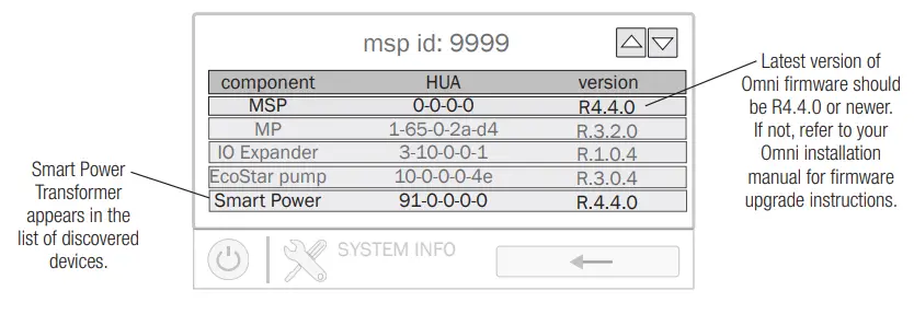
Verify Communication
Turn on power to both the Omni control and the Smart Power Transformer then navigate to the System Info screen on the Omni Control as shown below. Verify that the MSP version is R4.4.0 or newer and that the transformer’s Hayward Unique Address appears in the list. If the Smart Power Transformer’s HUA does not appear in the list of discovered devices, refer to the Troubleshooting section on page 12.
Configuration
Once the Smart Power Transformer is installed and communication has been confirmed, navigate to the config wizard on the Omni Control as shown below to configure the connected lights.
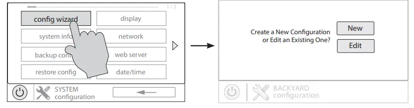
New Configuration
If the installation of the Smart Power Transformer was alongside a new installation of the Omni Control, select “New” and follow the instrucions in the “Configuration” section of the Omni Installation manual.
Edit Configuration
If the Smart Power Transformer was installed into a system with a pre-existing configuration, select “Edit” and follow the instructions on the following page to configure the lights.
On the following screen, press “Bodies of Water” and then select the body of water associated with the lights that you would like to configure.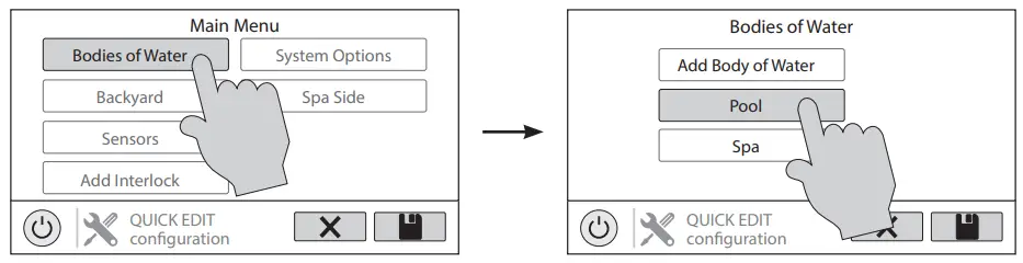 After selecting the body of water, press “Standalone Lights” and then “Add Standalone Light”.
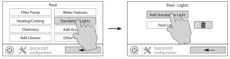 On the following screen, select the type of lights that you would like to configure and then give that group of lights a name.
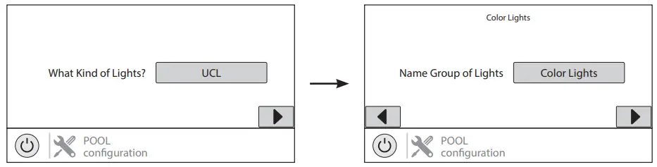 After naming the lights, select how many relays the lights are wired to. Note that the relays in this case are the “zones” on the Smart Power Transformer. If you would like the lights to always run together, then select multiple zones. If you would like then to run individually, then select only one.
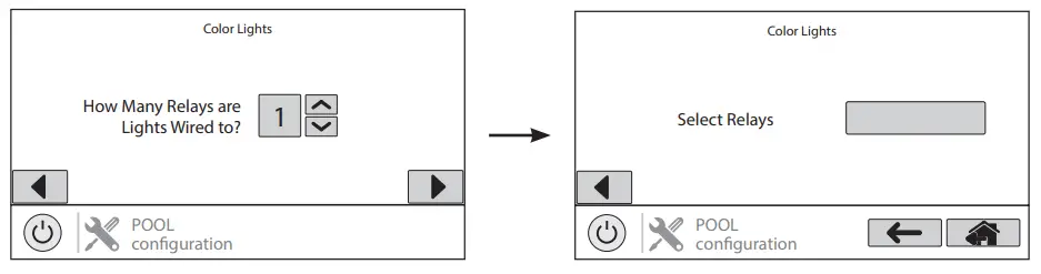 The Smart Power Transformer relays will appear as shown below. Select the relay(s) that the lights are wired to, press the check mark, and advance to the next screen. If the lights are to be used in Omni Direct mode, answer “Yes” to the question “Would you like to test for Omni Direct Capability?” If not, answer “No.”
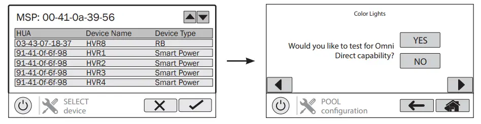 Once you are finished configuring the lights, save the configuration. The Omni system will reboot and the lights will be ready for operation.
Operation
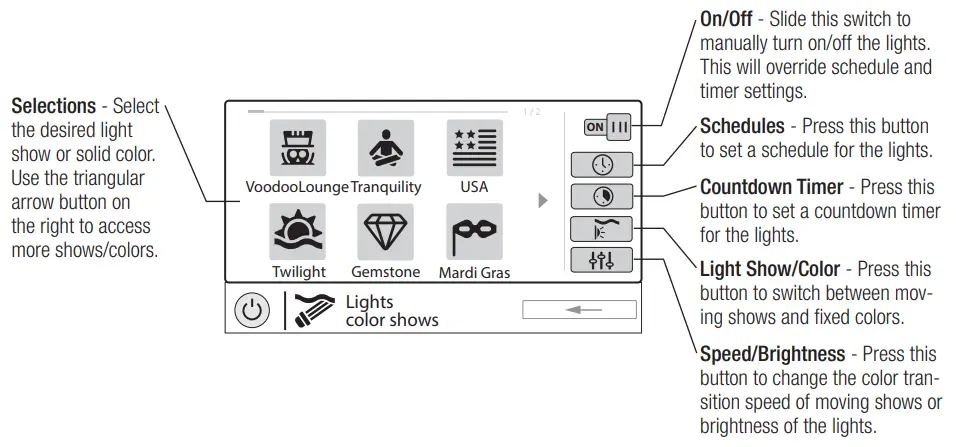
To operate the lights, navigate to the lights control screen on the Omni Control. Refer to the graphic below for an explanation of all the different light control functions available when the lights are set to Omni Direct mode. For other modes of operation, consult your Omni Control’s Operation manual.
If the lights are configured separately but you would like to run them together, both sets of lights can be added to a theme and they will run together whenever that theme is turned on. A theme takes a “snapshot” of the system’s state/settings and allows you to execute many pool functions with the press of just one button. For example, if you have pool lights and spa lights that are normally run separately but sometimes you would like to synchronize them together, create a theme with both sets of lights running in the desired show. Now, whenever that theme is turned on, the lights will turn on in that show and run together. For more information on themes including how to create and
operate them, refer to your Omni Control’s Operation manual.
Troubleshooting
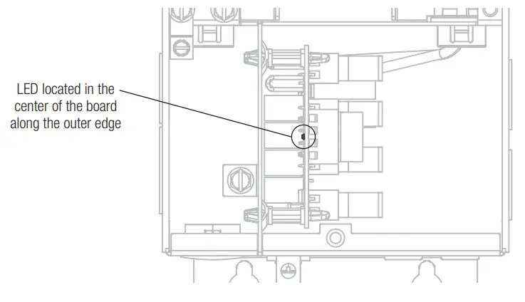
If the Smart Power Transformer is not communicating with the Omni Control, or some other issue has occurred, the LED on the circuit board can be helpful with troubleshooting by blinking a specific error code. See the graphic below for the location of this LED and the table below for error code blinking sequences.
| Blink Sequence | Indication | Solution |
| 6s on, 6s off | Normal operation | Normal operation |
| Solid Off | Hardware failure | Contact support |
| Solid On | Bootloader error | Check wiring; contact support |
| 1/2s on, 1/2s off | Firmware upgrade in progress | Normal operation for firmware upgrade |
| 6s on, 3s off | Configured Safe Mode | Normal operation for Service Mode when configured |
| 6s on, ls off | Unconfigured Safe Mode | Normal operation for Service Mode when unconfigured |
| 1 s on, 6s off | Communication error | Check wiring |
Hayward® Pool Products Limited Warranty
To original purchasers of this equipment, Hayward Pool Products, Inc. warrants its Universal ColorLogic® and CrystaLogic™ pool and spa lights, niches, pool light transformers, and couplers to be free from defects in materials and workmanship for a period of ONE (1) year from the date of purchase, when used in single family residential applications.
The limited warranty excludes damage from freezing, negligence, improper installation, improper use or care or any Acts of God. Parts that fail or become defective during the warranty period shall be repaired or replaced, at our option, within 90 days of the receipt of defective product, barring unforeseen delays, without charge.
Proof of purchase is required for warranty service. In the event proof of purchase is not available, the manufacturing date of the product will be the sole determination of the purchase date.
To obtain warranty service, please contact the place of purchase or the nearest Hayward Authorized Service Center. For assistance on your nearest Hayward Authorized Service Center please visit us at www.hayward.com.
Hayward shall not be responsible for cartage, removal, repair or installation labor or any other such costs incurred in obtaining warranty replacements or repair.
The Hayward Pool products warranty does not apply to components manufactured by others. For such products, the warranty established by the respective manufacturer will apply.
The express limited warranty above constitutes the entire warranty of Hayward Pool Products with respect to its’ pool products and is in lieu of all other warranties expressed or implied, including warranties of merchantability or fitness for a particular purpose. In no event shall Hayward Pool products be responsible for any consequential, special or incidental damages of any nature.
Some states do not allow a limitation on how long an implied warranty lasts, or the exclusion of incidental or consequential damages, so the above limitation may not apply to you. This warranty gives you specific legal rights, and you may also have other rights, which vary from state to state.
![]()
For further information or consumer technical support, visit our website at
www.hayward.com
Hayward is a registered trademark
of Hayward Industries, Inc. © 2022 Hayward Industries, Inc.
All other trademarks not owned by Hayward are the property of their respective owners.
Hayward is not in any way affiliated with or endorsed by those third parties.
USE ONLY HAYWARD GENUINE REPLACEMENT PARTS


