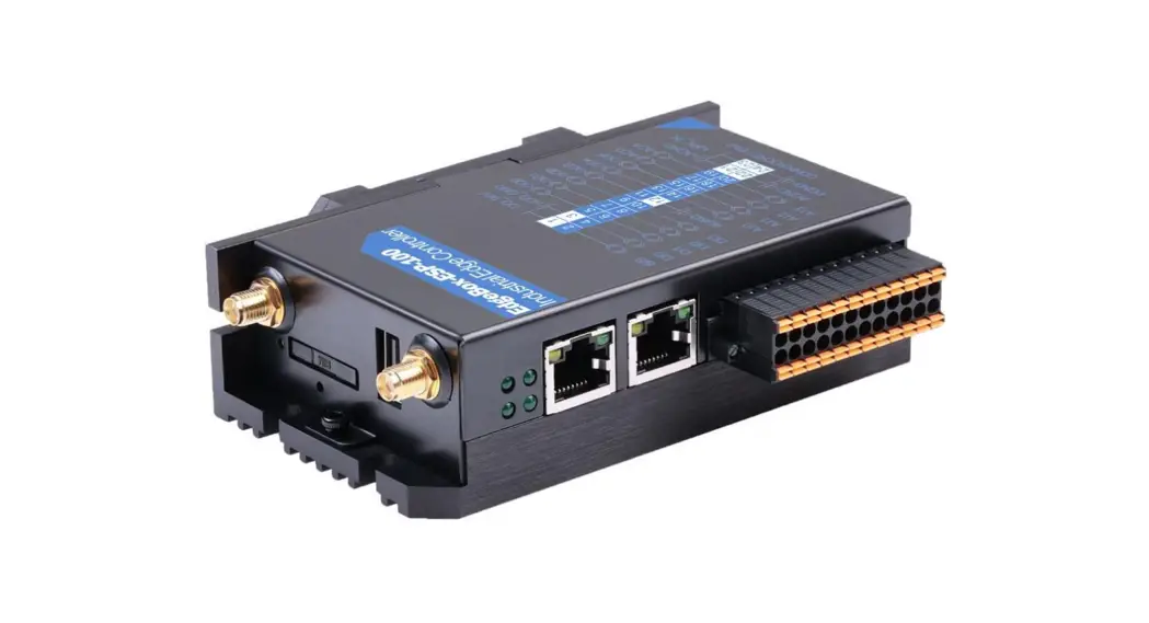
![]() EdgeBox-ESP-100 Industrial Edge Controller
EdgeBox-ESP-100 Industrial Edge Controller
User Manual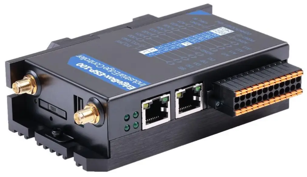 EdgeBox-ESP-100 User Manual
A light weight IoT controller for industrial applications
EdgeBox-ESP-100 Industrial Edge Controller
Revision History
| Revision | Date | Changes |
| 1.0 | 01-08-2022 | Initial |
Explanation of symbols used
The following symbols are used in these instructions:![]() NOTE
NOTE
NOTE indicates tips, recommendations and useful information on specific actions and facts.![]() NOTICE
NOTICE
NOTICE indicates a situation which may lead to property damage if not avoided.![]() CAUTION
CAUTION
CAUTION indicates a dangerous situation of risk
Introduction
EdgeBox-ESP-100 enabled SCADA equipment via software selectable 4G/LTE to remote networks or select Industrial Internet of Things (IIoT) Cloud platforms. Featuring an event-based engine that can trigger I/O or send SMS text messages based on real-time operational data, EdgeBox-ESP-100 controller can perform advanced local edge control and alert personnel of critical events. A built-in I/O concentrator allows the controller to collect sensor data and optimize cellular data consumption by optionally reporting only on an exception or only transmitting relevant data points. With built-in Ethernet, serial, I/O and GPS, EdgeBox-ESP100 controller easily integrate with existing equipment enabling remote monitoring and control for M2M applications in industries including oil and gas, water, utility, transportation and mining.
1.1. Features
- Rugged, reduced-maintenance hardware
- High isolation, surge, and short circuit protection
- Open architecture support custom programming
- Ethernet, I/O ,4G/LTE, CANopen and Modbus bridging
- Natively Supports Modbus & CANopen Protocols
- Cloud Connectivity to IIoT Cloud Platforms
- Integrated wired solution for all analog and discrete I/O interface designs
- IEC 61131-3 compliant programs support (under developing)
- 35mm DIN Rail support
- Wide power supply from 1.8 to 36V DC
These features make the EdgeBox-ESP-100 designed as a cost-effective controller that provides the functions required for a variety of field automation applications. The EdgeBox-ESP-100 monitors, measures, and controls equipment in a remote environment. It is ideal for applications requiring flow computation; Proportional, Integral, and Derivative (PID) control loops; logic sequencing control; and a gateway with flexible wireless and field sensors expansion.
1.2. Interfaces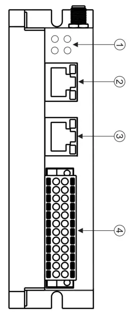
- LED
- EtherNET
- CAN bus and RS485
- Multi-Func phoenix connector
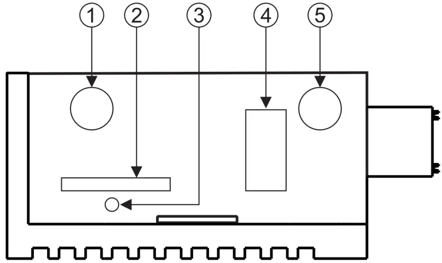
- Ant.1
- SIM CARD
- Reset
- USB PORT (5V power output only)
- Ant.2
NOTE:
- The Ant.1 is used for WI-FI signal, and Ant.2 is used for 4G/LTE in default.
- The USB port if ONLY used for 5V power output, no USB function.
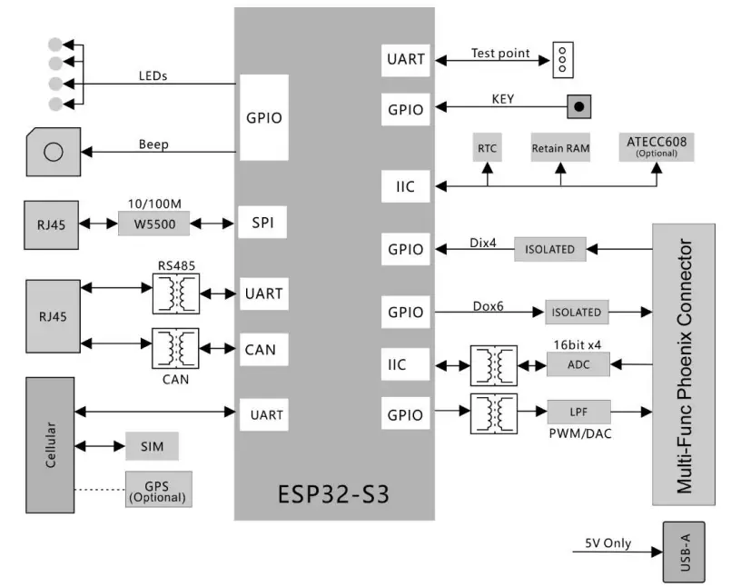
1.3. Block Diagram
The whole controller is built around ESP32 SOC. Refer to next figure for the block diagram.
Installation and Wiring
2.1. Mounting
DIN-rail mount is recommended. Refer to next figure for mounting orientation.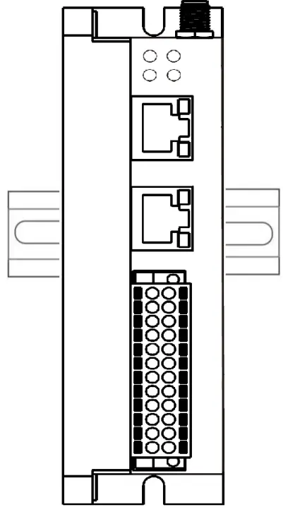 2.2. Connectors and Interfaces
2.2.1. Multi-Func phoenix connector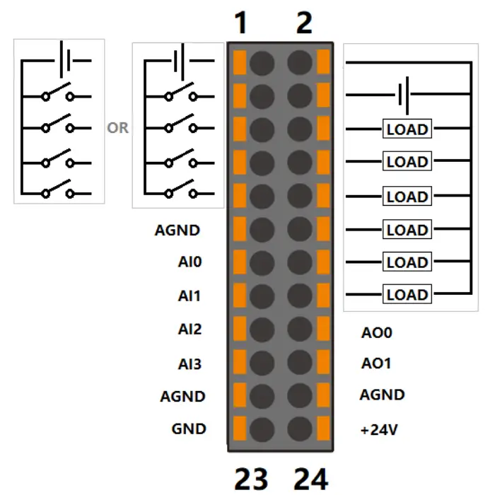
Note | Func name | PIN # | PIN# | Func name | Note |
| S/S | 1 | 2 | DO_24V | ||
| DI0 | 3 | 4 | DO_0V | ||
| DI1 | 5 | 6 | DO0 | ||
| DI2 | 7 | 8 | DO1 | ||
| DI3 | 9 | 10 | DO2 | ||
| AGND | 11 | 12 | DO3 | ||
| AI0 | 13 | 14 | DO4 | ||
| AI1 | 15 | 16 | DO5 | ||
| AI2 | 17 | 18 | AO0 | ||
| AI3 | 19 | 20 | AO1 | ||
| AGND | 21 | 22 | AGND | ||
| GND | 23 | 24 | +24V |
NOTE:
- 24awg to 16awg cable are suggested.
- GND and AGND are isolated.
- All AGND signals are connected internally.
- DC voltage for input is 24V(+- 10%).
- DC voltage for output should be 24V(+- 10%). , the current capacity is 1A.
2.2.2. Serial Port (CAN BUS and RS485)
| Pin# | Signal | Description |
| 4 | CAN_H | CAN |
| 5 | CAN_L | CAN |
| 7 | RS485_A | RS485 |
| 8 | RS485_B | RS485 |
| 1,2,3,6 | N.C | Not used |
| Green LED | LED CAN | Active when TX and RX of CAN BUS |
| Yellow LED | LED RS485 | Active when TX and RX of RS485 |
NOTE:
- The 120 Ohm termination resistor for RS485 has been installed inside.
- The 120 Ohm termination resistor for CAN BUS has been installed inside.
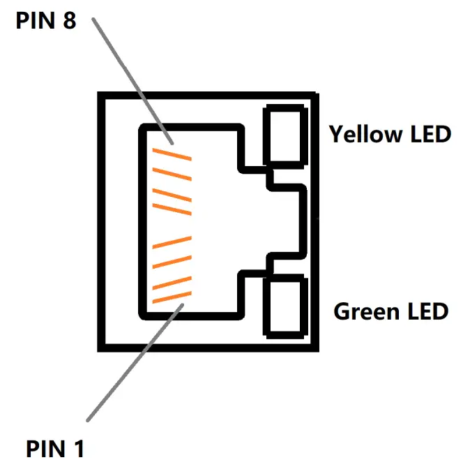
2.2.3. Ethernet
Ethernet interface comes from W5500, and connected ESP32 with SPI signals,10/100-BaseT supported, available through the shielded modular jack. Twisted pair cable or shielded twisted pair cable can be used to connect to this port.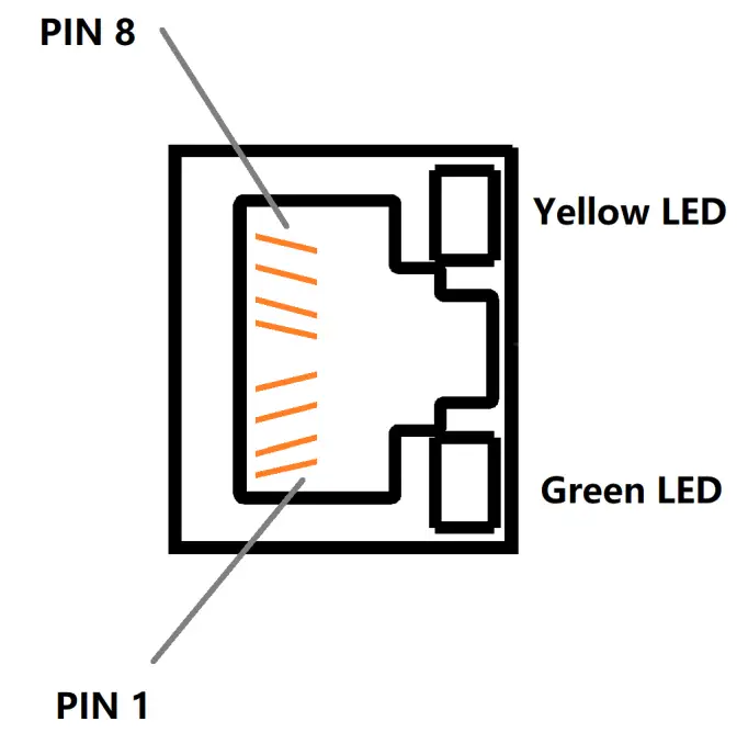
| Pin# | Signal | Description |
| 1 | TXP | |
| 2 | TXN | |
| 3 | RXP | |
| 6 | RXN | |
| 4,5,7,8 | N.C | Not used |
| Green LED | LINK | Active when LINK UP |
| Yellow LED | ACTIVE | Active when TX and RX data come through |
2.2.4. LED
| LED | Signal | Description |
| PWR | Power supply | |
| Cellular | 4G/LTE | |
| ACT | Multiplexed with U0TXD | |
| ERR | Multiplexed with U0RXD |
2.2.5. SMA Connector
There are two SMA Connector holes for antennas. The ANT1 is default used for Mini-PCIe socket and ANT2 is for Internal WI-FI signal from CM4 module. 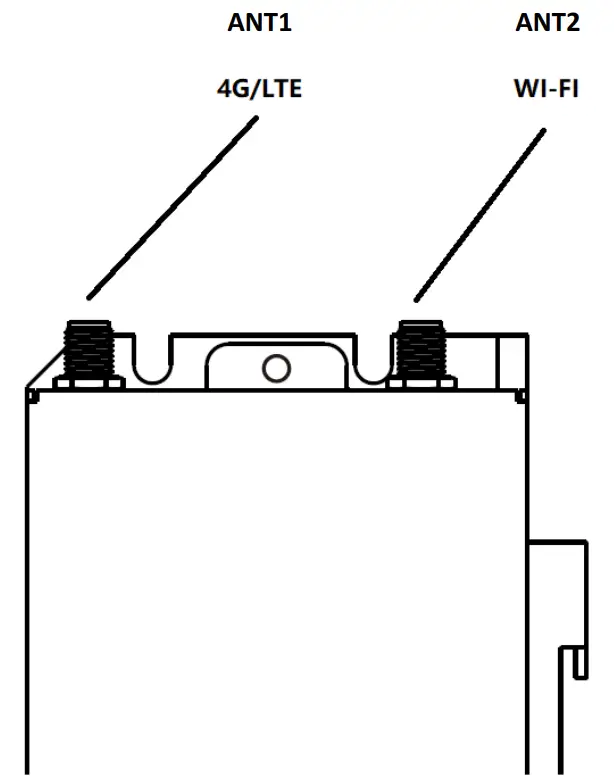 2.2.6. SIM card slot
The sim card is only needed in cellular network mode.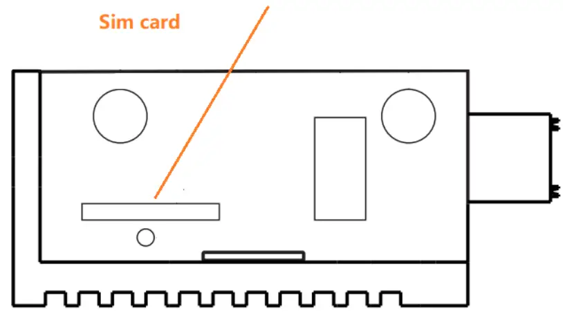 2.2.7. Reset button
 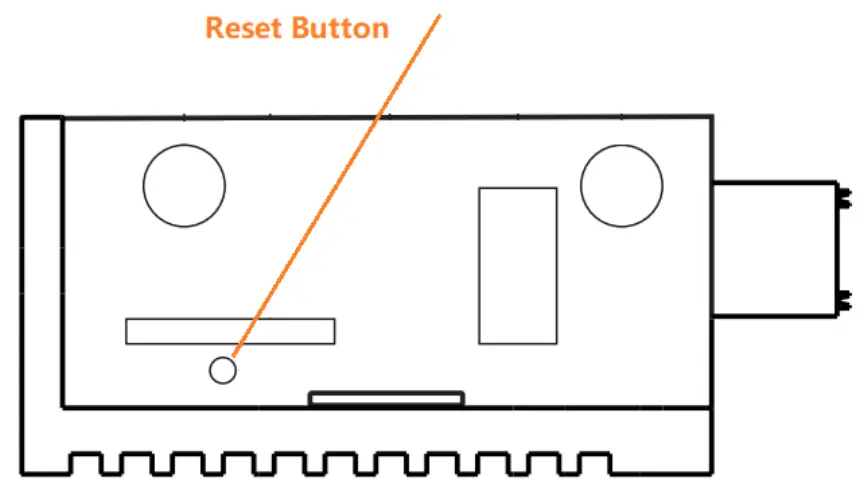 The reset button has multiple functions.
- When power up, the button is used to boot in download mode, it is useful if the OTA mode is crash.
- In APPs, the user software can use the button to “RESET” to default user configurations, such as IP Address, Wi-Fi information, or other behavior and action.
2.3. GPIO Multiplex
All used PINs are multiplexed as following figure.
| Name | IO of ESP32 | Type | Function |
| DO0 | IO40 | Digital output | Digital output 0 |
| DO1 | IO39 | Digital output | Digital output 1 |
| DO2 | IO38 | Digital output | Digital output 2 |
| DO3 | IO37 | Digital output | Digital output 3 |
| DO4 | IO36 | Digital output | Digital output 4 |
| DO5 | IO35 | Digital output | Digital output 5 |
| DI0 | IO4 | Digital input | Digital input 0 |
| DI1 | IO5 | Digital input | Digital input 1 |
| DI2 | IO6 | Digital input | Digital input 2 |
| DI3 | IO7 | Digital input | Digital input 3 |
| AO0 | IO42 | Analog output | Analog output 0 |
| AO1 | IO41 | Analog output | Analog output 1 |
| RS485 | IO17 | U1TXD | |
| IO18 | U1RXD | ||
| IO8 | RS485_RTS | ||
| 4G/LTE | IO48 | U2TXD | WWAN |
| IO47 | U2RXD | ||
| IO21 | PWR_KEY | ||
| IO16 | PWR_EN | ||
| Ethernet | IO10 | FSPI_CS0 | Connected to W5500 |
| IO11 | FSPI_MISO | ||
| IO12 | FSPI_MOSI | ||
| IO13 | FSPI_SCLK | ||
| IO14 | INT# | ||
| IO15 | RST# | ||
| CAN_TXD | IO1 | CAN BUS | |
| CAN_RXD | IO2 | CAN BUS | |
| TXD0/LED_ACT# | U0TXD | Programming/Debug and LED driver | |
| RXD0/LED_ERR# | U0RXD | ||
| Beep | IO45 | Beep | High active enables Buzzer |
| Reset | IO0 | Reset button | |
| I2C | IO19 | I2C_SCL | |
| IO20 | I2C_SDA | ||
| IO9 | Alarm or wake up from PCF8563 |
2.4. I2C
2.4.1. I2C devices
| Device | Address | Function |
| FM24CL64B | 0x50 | Retain memory |
| PCF8563 | 0x51 | RTC |
| Atecc608a | 0x68 | Crypto device |
| ADS1115 Or SGM58031 | 0x48 | ADC |
2.4.2. I2C PIN Map
| I2C PIN | ESP32 IO |
| I2C_SDA | IO20 |
| I2C_SCL | IO19 |
| I2C_INT | IO9 |
Main board
Top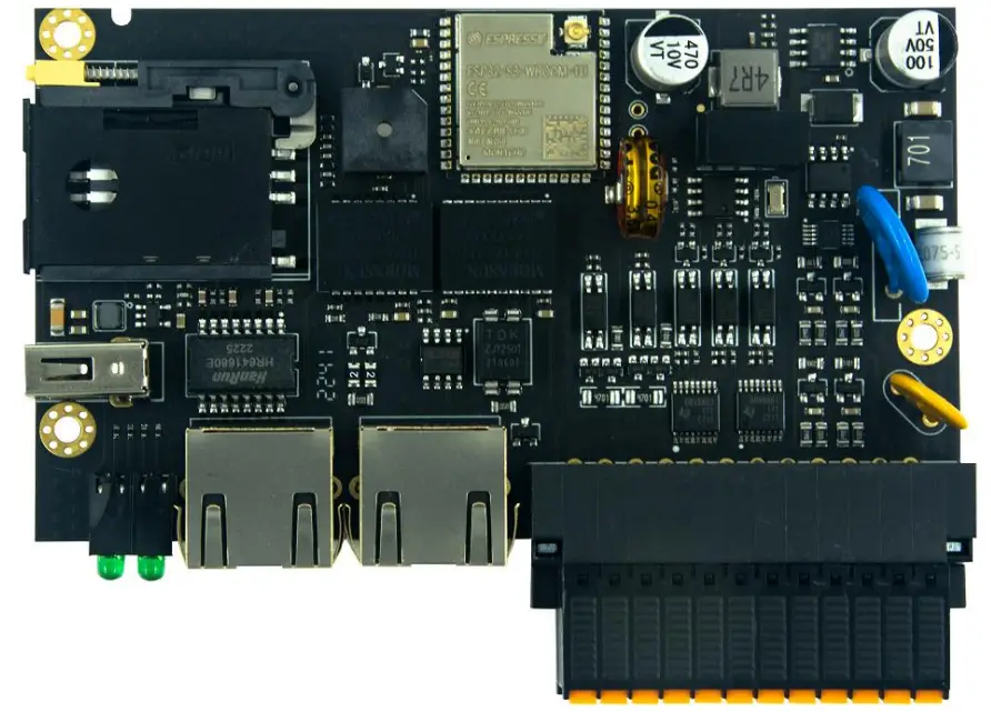 Bottom
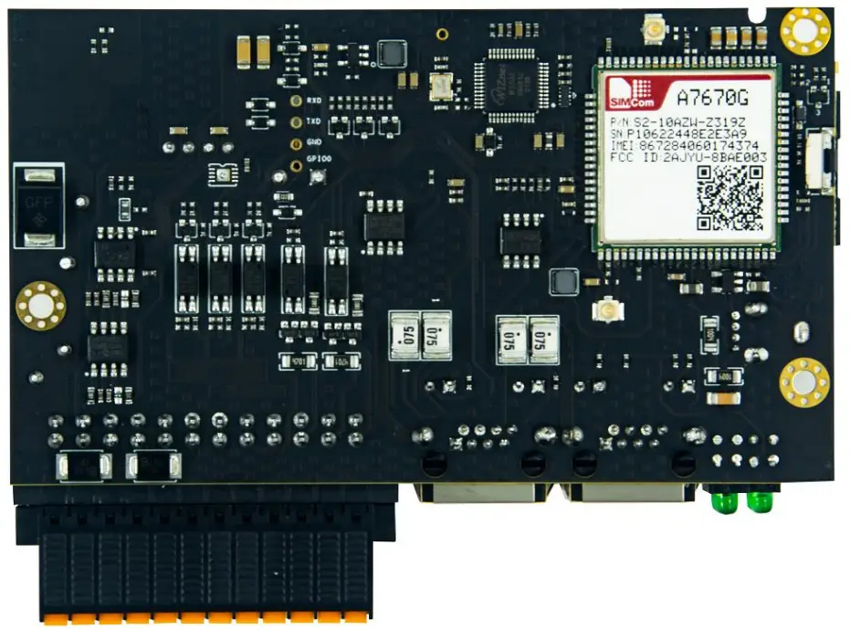 3.1. 4G/LTE
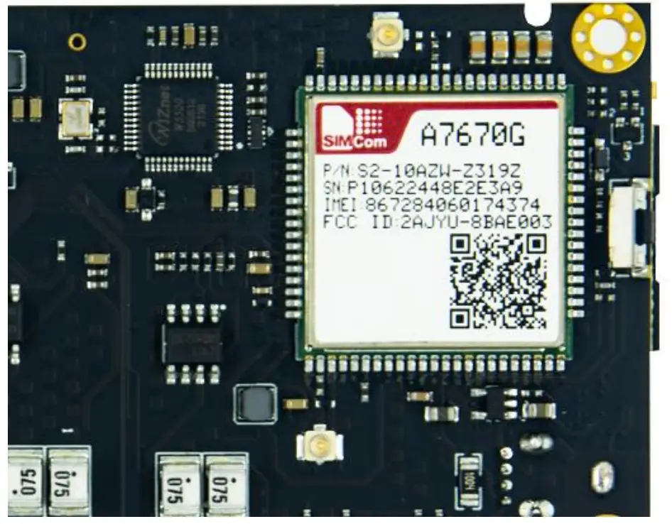
| A7670G 4G module | ESP32 IO | function |
| Enable power for A7670G through SY8089A | IO16 | PWR_EN |
| PWRKEY | IO21 | PWR_KEY |
| RXD | IO48 | U2TXD |
| TXD | IO47 | U2RXD |
3.2. Programming/Debug port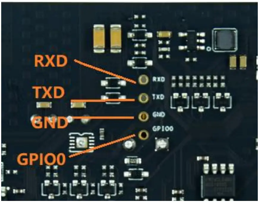 The GIPIO0 is also connected to the Reset Button. And the RXD, TXD of UART0 are used in download mode.
These allow the users to develop the EdgeBox-ESP-100 in bare meta.
| Debug port | ESP32 IO | Other Function |
| RXD | RXD0 | LED_ACT# |
| TXD | TXD0 | LED_ERR# |
| GND | GND | |
| GPIO0 | IO0 | RESET Button |
3.3. Analog Input
The AI (analog input) section of the controller is built around analog-to-digital converter ADS1115 or compatible with it. The resolution of the ADC is 16bit.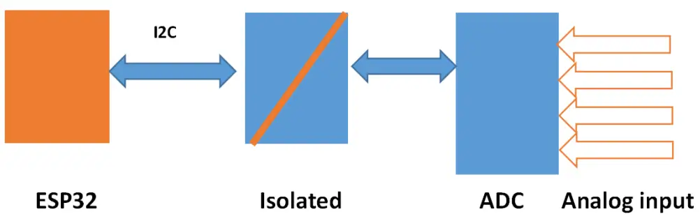
SGM58031 (I2C address 0X48) | IO |
| CH1+ | AI0 |
| CH2+ | AI1 |
| CH3+ | AI2 |
| CH4+ | AI3 |
| SDA | IO20/I2C_SDA |
| SCL | IO19/I2C_SCL |
NOTE:
- The default input type is 4-20ma.
- 0-10V Input type is optional.
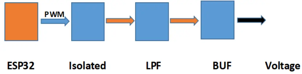
3.4. Analog Output
The dual AO channels are made up by PWM and LPF technology.
| Analog output | ESP32 IO |
| AO0 | IO42 |
| AO1 | IO41 |
Drivers and Programming
TBD
Applications
TBD
Electrical specifications
6.1. Power consumption
The power consumption of the EdgeBox-ESP-100 strongly depends on the application, the mode of operation and the peripheral devices connected. The given values have to be seen as approximate values.
Note: On condition of power supply 24V
| Mode of operation | Current(ma) | Power | Remark |
| Idle | 81 | ||
![]()


