FS COM AC-7072 Enterprise Wireless LAN Controller  Introduction
 Introduction
Thank you for choosing the enterprise wireless LAN controller. This guide is designed to familiarize you with the layout of the wireless LAN controller and describes how to deploy the wireless LAN controller in your network.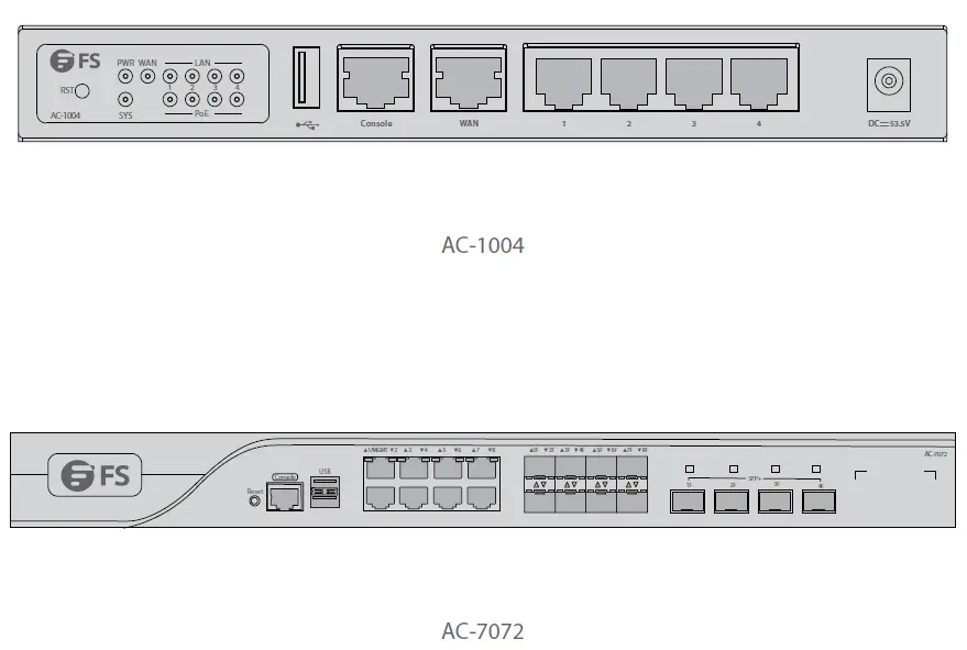
Accessories
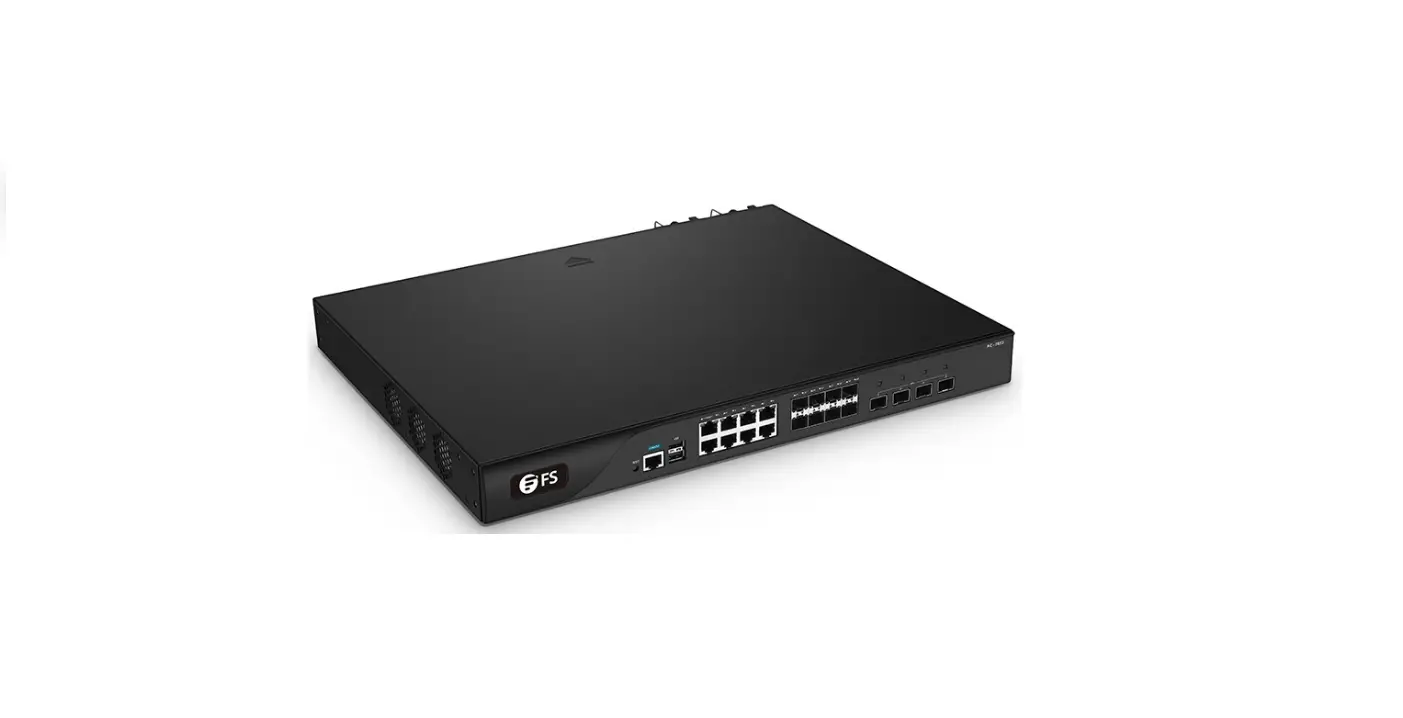
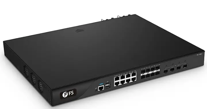
AC-7072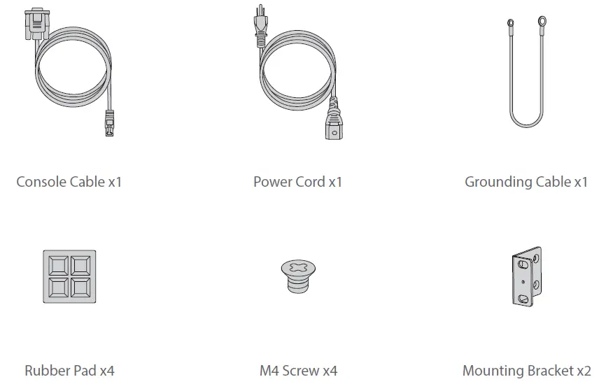
AC-1004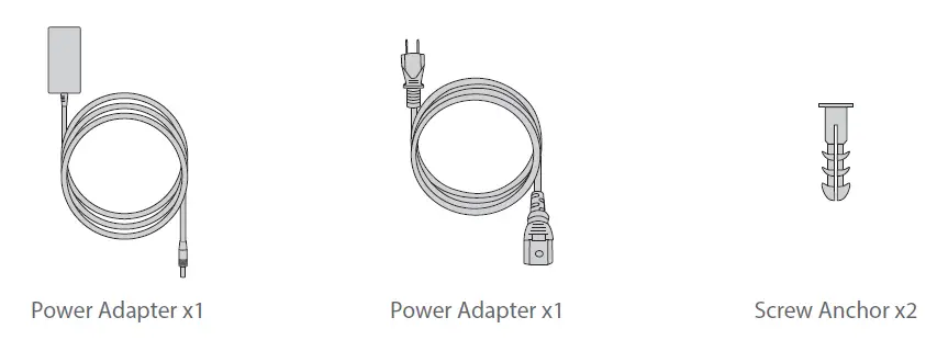
Hardware Overview
AC-1004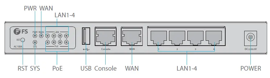
Front Panel Port
| Ports | Description |
| POWER | 53.5V DC power port |
| WAN | Wide Area Network interface |
| LAN1-4 | First Local Area Network interface |
| CONSOLE | A RJ45 console port for serial management |
| USB | A USB management port for software and configuration backup and offline software upgrade |
Front Panel Button
| Buttons | Description |
| RESET | Press it for more than 3s: Restore to Factory Default Settings. Press it for less than 3s: Restart the controller. |
Front Panel LED
| LEDs | State | Description |
|
SYS | Off | The system is abnormal. |
| Blinking Green | The system is initializing. | |
| Solid Green | The initialization process is complete. | |
| PWR | Off | The controller is powered off. |
| Solid Green | The controller is powered on. | |
| POE | Off | POE is powered off. |
| Solid Orange | POE is powered on. | |
|
LAN | Off | No Port Llink |
| Solid Green | Port 1000M Link Up | |
| Blinking Green | Port 1000M Data Transceiver | |
| Solid Orange | Port 100/10M Link Up | |
| Blinking Orange | Port 100/10M Data Transceiver | |
|
WAN | Off | No Port Link |
| Solid Green | Port 1000M Link Up | |
| Blinking Green | Port 1000M Data Transceiver | |
| Solid Orange | Port 100/10M Link Up | |
| Blinking Orange | Port 100/10M Data Transceiver |
Back Panel 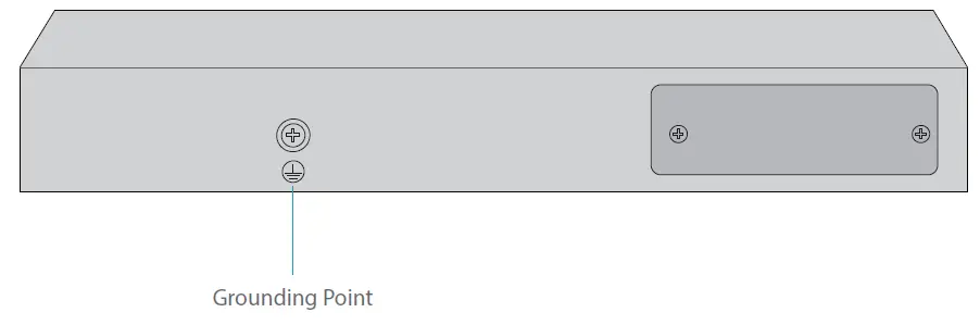
AC-7072 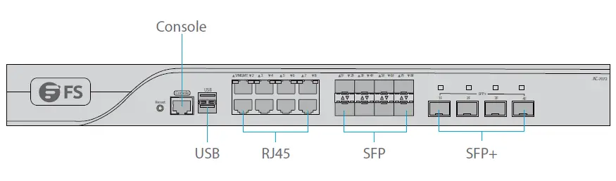
Front Panel Port
| Ports | Description |
| CONSOLE | A RJ45 console port for serial management |
| USB | A USB management port for software and configuration backup and offline software upgrade |
| RJ45 | 10/100/1000Base-T ports for Ethernet connection |
| SFP | Optical&Electrical Multiplexing 1000Base-X SFP port for 1G connection |
| SFP+ | 10GBASE-SR/LR SFP+ port for 10G connection |
Front Panel Button
| Buttons | Description |
| RESET | Restore to Factory Default Settings. |
Front Panel LED
| LEDs | State | Description |
|
SYSTEM | Blinking Green | The system is initializing. |
| Solid Green | The initialization process is complete. | |
| Solid Red | The system sends out an alarm. | |
| 1-8F Electrical Indicator | Solid Green | 1G LINK |
| Solid Yellow | 100/10M LINK | |
| Blinking | Data Transceiver | |
| 1F-8F 1G Optical Indicator | Blinking Green | Link |
| Solid Green | Data Transceiver | |
| 1F-4F 10G Optical Indicator | Blinking Green | Link |
| Solid Green | Data Transceiver |
Back Panel 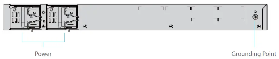
Installation Requirements
Before you begin the installation, make sure that you have the followings:
- Phillips screwdriver.
- Standard-sized, 19″ wide rack with a minimum of 1U height available.
- Category 5e or higher RJ-45 Ethernet cables and fiber optical cables for connecting network devices.
Site Environment
- Make sure the installation site is dry and flat.
- Keep the controller far away from the heat source.
- Ensure that the controller is properly grounded.
- Wear an anti-static wrist strap during installation and maintenance.
- Keep the controller and installation tools away from walkways.
- Use UPS (Uninterruptible Power Supply) to prevent power failure and other interference.
Mounting the Wireless LAN Controller
Desk Mounting 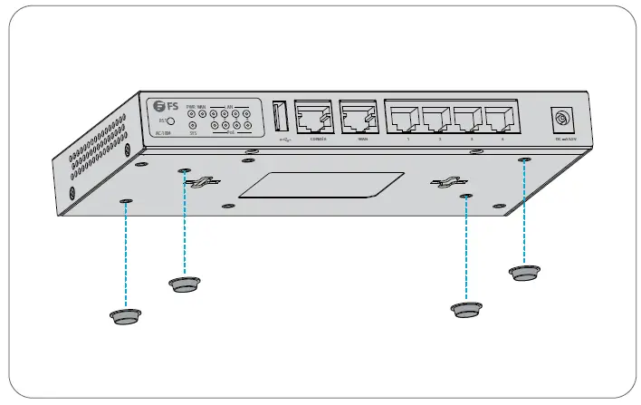
- Attach four rubber pads to the bottom.
- Place the controller on a desk.
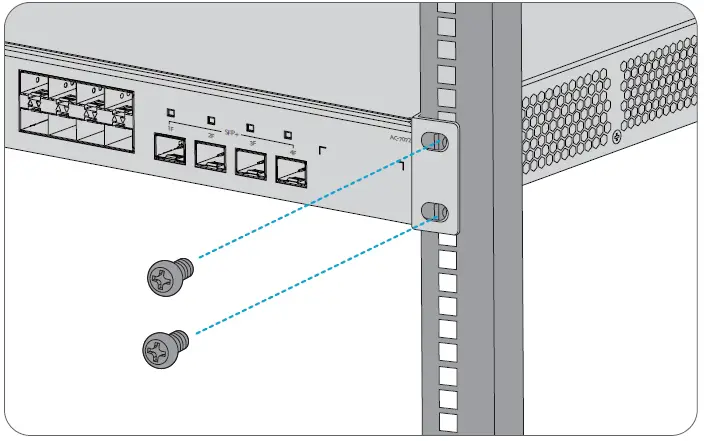
Rack Mounting 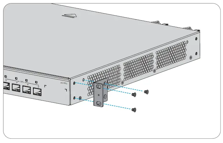
- Secure the mounting brackets on the two sides of the controller with six M4 screws.

- Attach the contro ller to the rack using four M6 screws and cage nuts.
Grounding the Controller 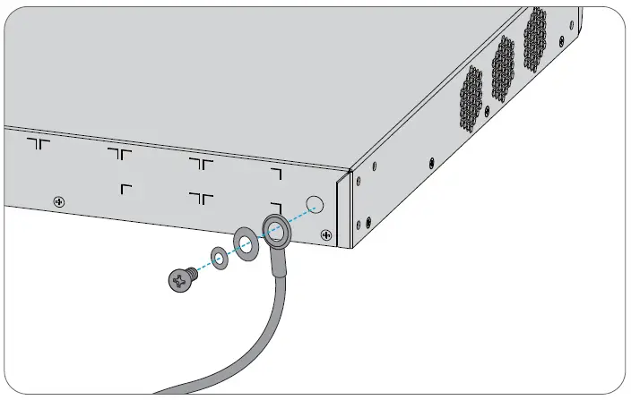
- Connect one end of the grounding cable to a proper earth ground, such as the rack in which the controller is mounted.
- Secure the grounding lug to the grounding point on the controller back panel with the washers and screws.
Connecting the Power 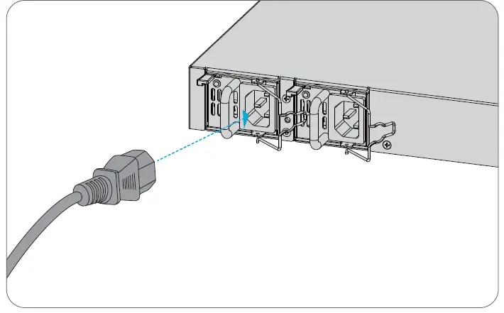
- Plug the AC power cord into the power port on the back panel.
- Connect the other end of the power cord to an AC power source.
Connecting the Console Ports 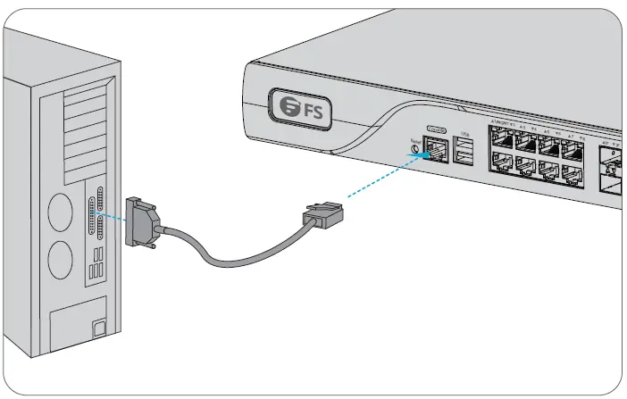
- Insert the RJ45 connector into the RJ45 console port on the front panel.
- Connect the DB9 female connector of the console cable to RS-232 serial port on the computer.
Connecting the RJ45 Ports 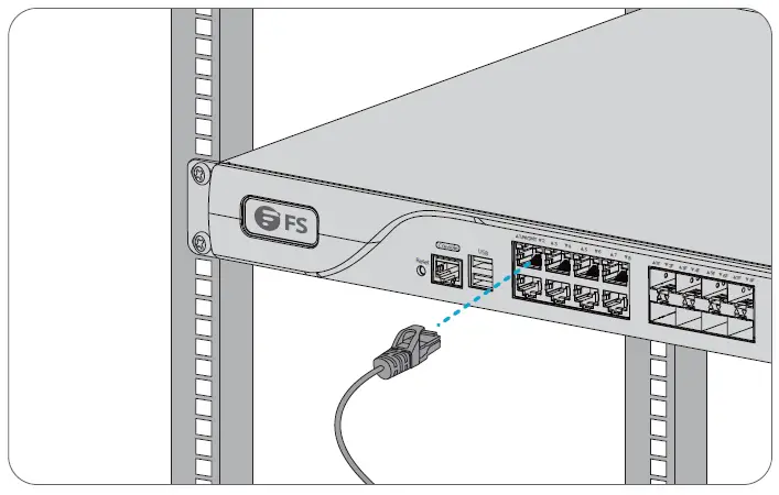
- Connect an Ethernet cable to the RJ45 port of a computer or other network devices.
- Connect the other end of the Ethernet cable to the RJ45 port of the controller.
Connecting the SFP Ports 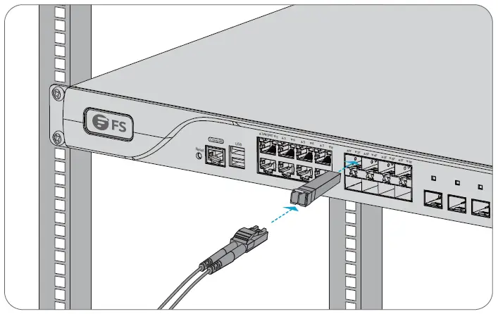
- Plug the compatible SFP transceiver into the SFP port.
- Connect a fiber optic cable to the fiber transceiver. Then connect the other end of the cable to another fiber device.
NOTE: The AC-1004 can’t be mounted in the rack. Other detailed steps of its installation are the same as the AC-7072.
Configuring the Wireless LAN Controller
Configuring the Controller Using the Console Port
Step 1: Connect a computer to the controller’s console port using the supplied console cable.
Step 2: Start the terminal simulation software such as HyperTerminal on the computer.
Step 3: Set the parameters of the HyperTerminal: 9600 bits per second, 8 data bits, no parity, 1 stop bit and no flow control. 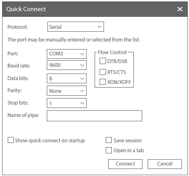
Step 4: After setting the parameters, click Connect to enter.
Troubleshooting
The Screen Displays Request Timed Out
- Check if the network cable is intact.
- Check if the hardware connection is correct.
- The system status indicator on the device panel and the NIC indicator on the computer must be lit.
- The computer’s IP address setting is correct.
Online Resources
- Download: https://www.fs.com/products_support.html
- Help Center: https://www.fs.com/service/fs_support.html
- Contact Us: https://www.fs.com/contact_us.html
Product Warranty
FS ensures our customers that if there are any damage or faulty items due to our workmanship, we will offer a free return within 30 Days from the day you receive your goods. We will also offer free software update service. This excludes any custom made items or tailored solutions.
Warranty: This product enjoys 3 years limited warranty against defect in materials or workmanship. For more details about warranty, please check at
https://www.fs.com/policies/warranty.html
Return: If you want to return item(s), information on how to return can be found at https://www.fs.com/policies/day_return_policy.html
References
 FS.com - Data Center, Enterprise, Telecom
-
Contact Us - FS.com
-
Kontakt - FS.com Deutschland
-
Rückgaberecht - FS.com Deutschland
-
Ein weltweit führender Anbieter von Hochgeschwindigkeits-Konnektivitätsgeräten und -lösungen. - FS.com Deutschland
-
Technische Dokumente - FS.com Deutschland
-
Hilfezentrum - FS.com Deutschland
-
Comment Nous Contacter - FS.com France
-
Politique de retour - FS.com France
-
Fournisseur leader de solutions et matériels de connectivité à haut débit - FS.com France
-
Documents techniques - FS.com France
-
Centre d'aide - FS.com France
-
Return Policy - FS.com
-
Products Warranty - FS.com
-
Technical Documents - FS.com
-
Help Center - FS.com


