![]()
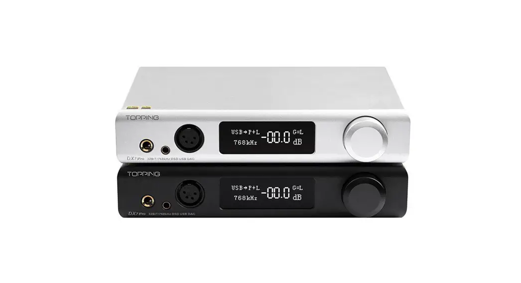
Thank you for purchasing TOPPING DX7 Pro+ ! The DX7 Pro+ is a high-performance device which has six digital inputs, two Line Out outputs and three headphone outputs. DX7 Pro+ is compatible with 768kHz/32bit and DSD512, it can be used as not only a HIFI DAC & headphone amp, but also a simple DAC or DAC + pre-amplifier. We hope it could bring you more fun at enjoying music. Now we recommend you read this manual so that you can use all the features of DX7 Pro+ correctly.
Contents list
DX7 Pro+ x 1
Remote control x 1
USB cable x 1
6.35 mm to 3.5 mm adaptor x 1
Bluetooth antenna x 1
AC cable x 1 User manual x 1
Warranty card x 1
Note: You can download the driver and user manual on http://www.topping.audia
Attribute
| Measured | 22.0cm x 18.0ran x 4.4cm |
| weight | 1.07Kg |
| Power input | 100-240VAC 50H:1130H1 |
| Signal input | USEWBUOPT/COAX/IIStAES |
| Line Out output | XLRIRCA |
| Line Out output | XLFt/RCA |
| HoedphoneAmpliller Output | 6.35mm headphone output jack |
| 4.4mm headphone MAMA Ian | |
| 4PIN-XLR headphone output jack | |
| Display | White OLEO |
| Standby power consumption | <2.5W |
| Power consumption in normal Mar | <IOW |
| Power consumption in normal Mar | <IOW |
Front panel
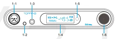 1-1 4-PIN-XLR headphone output jack
1-2 4.4mm headphone output jack
1-3 6.35mm headphone output jack
1-4 OLED screen
1-5 Remote control receiver
1-6 Volume knob/Muti-function Button
Rear panel
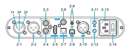 2-1 Right channel balanced XLR output*
2-2 Left channel balanced XLR output*
2-3 Left channel single-ended RCA output
2-4 Right channel single-ended RCA output
2-5 IIS input
2-6 Coaxial SPDIF input
2-7 Optical SPDIF input
2-8 Bluetooth input
2-9 USB input
2-10 AES input
2-11 12V Trigger In
2-12 12V Trigger Out
2-13 Power input (AC 100-240V 50Hz/60Hz) 2-14 Power switch
*Note: Description of XLR male connector pin definition. 1.GND 2.+ 3.-
Display
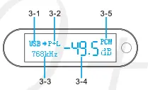
3-1 Input
3-2 Output
3-3 Current sampling rate
3-4 Volume
3-5 PCM/DSD format indication
Remote control
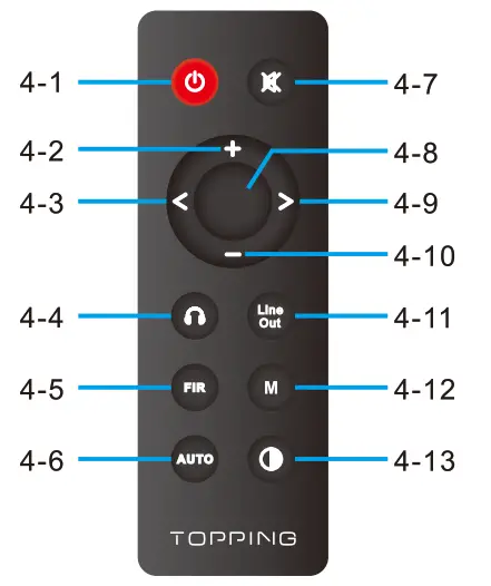 4-1 Standby
4-2 Volume up
4-3 Switch to previous input
4-4 Headphone amp output
4-5 Filter setting
4-6 Auto power on&standby
4-7 Mute
4-8 Headphone amp & Line Out output
4-9 Switch to next input
4-10 Volume down
4-11 Line Out output
4-12 Headphone amp gain
4-13 Brightness
*Note:
- ‘DIS: A” has the same brightness as “DIS: M’. The differences lie in when there is no operation after 30 seconds under’ DIS: A” mode, the screen will be automatically turned off, only display a dot at the bottom right corner. You can press any button to light up the screen.
- When DX7 Pro+ is in Bluetooth input state, keep pressing the brightness button for 3 seconds to disconnect the existing Bluetooth connection and forcibly enter into Bluetooth pairing state.
Input range
| USB IN | PCM 44.1kHz-768kH2116bit-32bit |
| DSD DSD64-DSD512 (Native) . DS1364-DSD256 (DoP) | |
| COAX/OPT/AES IN | PCM 44.1 kHz-192kHz/16bit-24bit |
| DSD DSD64 (DoP) | |
| 115 IN | PCM 44.1 kHz-768kHz/16bit-32bit |
| DSD 0SD64-050512 (Native) .05064-D50256 (DoP) | |
| BT IN | AAC/SBC/APTX/APTX LUAPTX HD/LDAC |
Specifications
| DX7 Pro+ DAC parameters (LIneOut/USB In@96kHz) | ||
| RCA | XLR | |
| THD•Ntat kHz (A-wt) | <0.00008% | <0.00006% |
| TND 620-20kHz 90kBw | <0.0008% | <0.0003% |
| SNR@lkHz (A-wi) | 127dB | 133dB |
| Dynamic range @1kHz (A-wi) | 127dB | 133d8 |
| Frequency Response | 20Hz-20kHz (±0.1dB) | 20Hz-20kHz (30.1dB) |
| 20Hz-40kHz (20.30) | 20Hz-40kHz (30.3013) | |
| Output Level | 2.1Vrms @OdBFS | 4.2Vrms @OdBFS |
| Noise©A-wt | <1.0uVrms | <1.0uVrms |
| Channel Crosstalk | -126013 @1kHz | -13908 @1kHz |
| Channel Balance | 0.3 dB | 0.3 dB |
| Output Impedance | 1000 | 1000 |
*Note: The above data is the result of the tes in TOPPING laboratory under AC220V 50Hz condition.
| DX7 Pro+ Headphone Amplifier specifications (USB In096kHz) | ||
| 6.35mm headphone Jack | 4-PIN-XLR headphone Jack | |
| THD+N @1kHz (A•wt) | <0.00009%@Output<150mW(320) | <0.00009% ©Output=1S0mW (320) |
| <0.00007% ©Output=15mW(3000) | <0.00007% @Ouiput=15mW(3000) | |
| THD (a20-20kHz 90kBW | 40.00060%@Output=150mVv(320) | <0.00060% gOutpet=150mw (320) |
| <0.00040% gOutput415mW(3000) | <0.00040% @Output. ISmW(3000) | |
| SNR fkIAAX OUT I kHz (A-w0 | 127dB ic 1kHz | 127dB (§21kHz |
| Dynamic Range al kHz (A-w0 | 127dB @1kHz | 127dB @1kHz |
| Frequency Response | 20Hz-20kHz (30.10B) | 20Hz-20kHz (30.1dB) |
| 20Hz-40kHz(30.30B) | 20Hz-40kHz (30.3dB) | |
| Output Level | 6.2Vpp @G=L | 6.2Vpp @G=L |
| 27.8Vpp @G=H | 27.8Vpp @G=H | |
| Noise@A-wt | <1.4uVrms @G. L | <1.2uVrms 6tG=L |
| <2.5uVrms @G=1-1 | <2.5uVrms ©GeH | |
| Channel Crosstalk | -120dB @1kHz | -120dB @1kHz |
| Gain | G=L 6.9dB (Vrms/FS) | G=L 6.9dB (Vrms/FS) |
| G=H 20dB (Vrms/FS) | G=H 20dB (Vrms/FS) | |
| Channel Balance | 0.3 dB | 0.3 dB |
| Output Impedance | <0.10 | <0.10 |
| Output Power | 1900mW x 2 @320 THD+N<1% | 1900mW x 2 @320 THD+N<1% |
| 1350mW x 2 @640 THD+N<1% | 1350mW x 2 @640 THD+N<1% | |
| 320mW x 2 @3000 THD+N<1% | 320mW x 2 @3000 THD+N<1% | |
| Load impedance | >80 | >80 |
Note: The above data is the result of the test in TOPPING laboratory under AC220V 50Hz condition.
Operation
Power on & off / standby operation:
- Power on & off: Press the power switch on the rear panel to turn DX7 Pro+ on or off.
- Standby setting: When it is working, press and hold the knob on the front panel to enter standby state and short press to exit standby state when it is in standby. Or you can directly press the standby button on remote control to enter or exit standby state.
12V Trigger In/Out: The 12V Trigger In/Out allows the DX7 Pro+ to be activated by other devices or to activate other devices via a 3.5mm mini phone plug cable. The connected device must be equipped with a 12V Trigger In/Out to use this feature.
Auto power on&standby: Three options are available and can be set either in the setup menu or by pressing the Auto power on&standby button on the remote control
- SIG: On & standby based on input status. If the current input is not connected or input signal is invalid in 1 minute, it will automatically enter the standby state. Once having detected valid signal, it will automatically return to working state.
- TRG: On & standby based on trigger signal. When DX7 Pro+’s Trigger In is connected to another device’s 12V Trigger Out, DX7 Pro+’s power on/standby can be controlled through this device. DX7 Pro+ will be powered on when Trigger In detects a 12V signal, and returns to standby state in case the 12V signal disappears.
- OFF: Disabled this function
Volume setting:
(1) The enter and exit of mute state: Press the mute button on the re mote control to set mute, press the mute button again or adjust the volume to exit mute state.
(2) Volume adjusting: You can directly turn the volume knob or press the volume up or down button on the remote control to adjust the volume.
Note that long pressing the volume up/down button on the remote control will quickly adjust the volume, so please be careful in order to protect your hearing.
Input channel switching: Press the knob on the front panel or the “Switch to previous input button” and the “Switch to next input button’ on the remote control to switch the input in cycle. Output channel switching: Double-click the knob on the front panel or use the Headphone amp output button, Headphone amp & Line Out output button, Line Out output button on the remote control to set the output channel. (Press the Line Out output button can select RCA or XLR or RCA+XLR output)
Enter the setup menu: After switching the power switch to ‘power off”, press and hold the knob on the front panel while switching to “power on” to enter the setup menu of DX7 Pro+. Change and save of settings: (1) The volume knob on the front panel: rotate the knob to enter the next setting item, press the knob to set different parameters. You need to choose the 15th option of ‘Save and exit’ after setting the parameter. (2) The remote control: press the volume up/down button to enter the previous/next setting item, press the middle button to set different parameters. You need to choose the 15th option of ‘Save and exit” after setting the parameter.
Setting descriptions:
- Auto power on&standby setting (Available for remote control setting)
| Screen display | Description |
| AUTO I SIG | On & standby based on input status (Default) |
| AUTO I TRG | On & standby based on trigger signal |
| AUTO I OFF | Disabled this function |
2. Screen brightness setting (Available for remote control setting)
| Screen display | Description |
| Display I L | Low |
| Display I M | Mid (Default) |
| Display I H | High |
| Display I A | Mid brightness and screen will be turned off automatically after no operation for 30s |
3. Headphone amp gain (Available for remote control setting)
| Screen display | Description |
| GAIN I L | Headphone Amp-Low gain (Default) |
| GAIN I H | Headphone Amp-High gain |
4. Output channel setting (Available for remote control setting)
| Screen display | Description |
| OUTPUT I PO | Headphone amp output |
| OUTPUT I LO | Line Out output |
| OUTPUT I P0+1-0 | Headphone amp & Line Out output (Default) |
5. Line Out mode setting
| Screen display | Description |
| LO Mode I PRE | Per-Amp mode (volume adjustable) (Default) |
| LO Mode I DAC | DAC mode (volume nonadjustable) |
6. Line Out output setting (Available for remote control setting)
| Screen display | Description |
| LineOut 1 RCA+XLR | RCA&XLR Output simultaneously (Default) |
| LineOut 1 RCA | RCA Output only |
| LineOut 1 XLR | XLR Output only |
7. Bluetooth setting
| Screen display | Description |
| BT I ON | Bluetooth enabled (Default) |
| BT I OFF | Bluetooth disabled |
8. DAC mode setting
| Screen display | Description |
| DAC Mode I ASYNC | Asynchronous mode (Default) |
| DAC Mode I SYNC | Synchronous mode |
9. PCM filter setting (available for remote control setting, set PCM filter mode when playing PCM)
| Screen display | Description |
| PCM FIR 11 | Fast roll off apodizing |
| PCM FIR 12 | Slow roll off minimum |
| PCM FIR 13 | Fast roll of minimum (Default) |
| PCM FIR 14 | Slow roll off linear |
| PCM FIR 15 | Fast roll of linear |
| PCM FIR 16 | Brick-wall |
| PCM FIR 17 | Fast roll of corrected minimum |
10. DSD filter setting (available for remote control setting, set DSO filter mode when playing DSD)
| Screen display | Description |
| DSD FIR 1 1 | 47kHz (Default) |
| DSD FIR 12 | 50kHz |
| DSD FIR 1 3 | 60kHz |
| DSD FIR 14 | 70kHz |
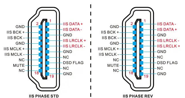
11.115 interface phase setting
| Screen display | Description |
| 115 Phase I STD | Standard phase (Default) |
| IIS Phase I REV | Reverse phase |
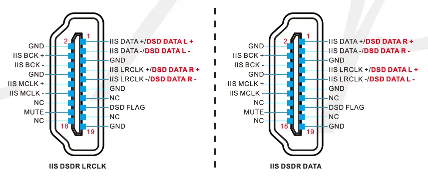
12. DSD channel setting for the 115 interface
| Screen display | Description |
| IIS DSDR I LRCLK | DSDR using LRCLK (Default) |
| IIS DSDR I DATA | DSDR using DATA |
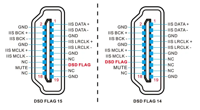
13. DSD flag bit setting for the IIS interface
| Screen display | Description |
| IIS DSD Flag I 15 | Set pin 15 as the flag bit (Default) |
| IIS DSD Flag I 14 | Set pin 14 as the flag bit |
14. Remote control setting
| Screen display | Description |
| IR Receive I ON | Remote control enabled (Default) |
| IR Receive I OFF | Remote control disabled |
15. Save settings and restart
| Screen display | Description |
| Save and exit | Save settings and restart |
16. Factory reset
| Screen display | Description |
| Factory reset | Reset default |
Precautions for daily use
- Do not keep the unit in a hot, humid environment or hit the unit strongly.
- Opening the case instantly voids the warranty!
- Indoor use only.
- Topping accepts no liability for any loss or damage arising directly or indirectly from the failure of DX7 pro+.
FCC WARNING
This device complies with part 15 of the FCC Rules. Operation is subject to the following two conditions: (1) this device may not cause harmful interference, and (2) this device must accept any interference received, including interference that may cause undesired operation. Any changes or modifications not expressly approved by the party responsible for compliance could void the user’s authority to operate the equipment.
NOTE: This equipment has been tested and found to comply with the limits for a Class B digital device, pursuant to Part 15 of the FCC Rules. These limits are designed to provide reasonable protection against harmful interference in a residential installation. This equipment generates, uses and can radiate radio frequency energy and, if not installed and used in accordance with the instructions, may cause harmful interference to radio communications.
However, there is no guarantee that interference will not occur in a particular installation. If this equipment does cause harmful interference to radio or television reception,
which can be determined by turning the equipment off and on, the user is encouraged to try to correct the interference by one or more of the following measures:
— Reorient or relocate the receiving antenna.
— Increase the separation between the equipment and receiver.
— Connect the equipment into an outlet on a circuit different from that to which the receiver is connected.
— Consult the dealer or an experienced radio/TV technician for help.
To maintain compliance with FCC’s RF Exposure guidelines, This equipment should be installed and operated with minimum distance between 20cm the radiator your body: Use only the supplied antenna.


