Breaburn 4235 Premier Series Programmable Thermostats User Manual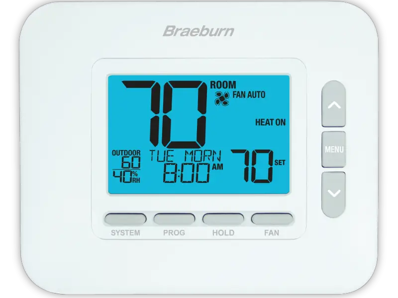
![]() Warning
Warning
For installation by experienced service technicians only.
![]() Caution
Caution
Possible electric shock or damage to equipment can occur. Disconnect power before beginning installation.
This thermostat requires 24 Volt AC Power or 2 properly installed “AA” Alkaline batteries for proper operation. When connecting 24 Volt AC Power, the batteries may be installed as a backup.
For use only as described in this manual. Any other use will void warranty.
This manual is for Installer use only – do not leave with end user.
SPECIFICATIONS
This thermostat is compatible with:
- Single stage conventional and heat pump systems
- Single stage heat pumps with auxiliary heat
- Heat pump systems with 2 compressors and auxiliary heat (4235 only)
- Conventional systems up to 2 stages of heat and 2 stages of cool (4235 only)
- 250 – 750 millivolt heating only systems
- 2 or 3 wire hydronic zone systems
Electrical and Control Specifications
- Electrical Rating: 24 Volt AC
- 1 amp maximum load per terminal
- AC Power: 18 – 30 Volts AC
- DC Power: 3.0 Volt DC (2 “AA” Alkaline Batteries Included)
- Control Range: 45° to 90° F (7° to 32° C)
- Temperature Accuracy: +/- 1° F (+/- .5° C)
- Outdoor Temperature Display Range:
- 40° to 120° F (-40° to 49° C)
- DRY1, DRY2 Terminals: Dry Contact Relay
Humidity Control Specifications
- Humidification Control Range: 10% – 50% RH
- Dehumidification Control Range: 40% – 80% RH
Terminations
4030:
Rc, Rh, W1/E, Y1, G, O/B/V3, L, C, S1, S2, DRY1, DRY2
4235:
Rc, Rh, W1/E, W2/AUX, Y1, Y2, G, O/B/V3, L, C, S1, S2, DRY1, DRY2
INSTALLATION
![]() Warning Disconnect power before beginning installation
Warning Disconnect power before beginning installation
Thermostat Location
Install the thermostat approximately 5 feet (1.5m) above the floor in an area that has a good amount of air circulation and maintains an average room temperature.
Avoid installation in locations where the thermostat can be affected by drafts, dead air spots, hot or cold air ducts, sunlight, appliances, concealed pipes, chimneys and outside walls.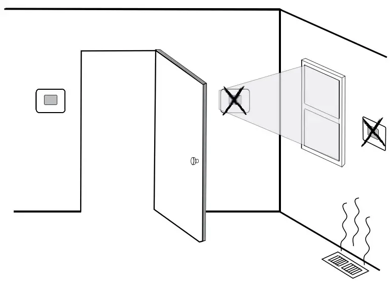
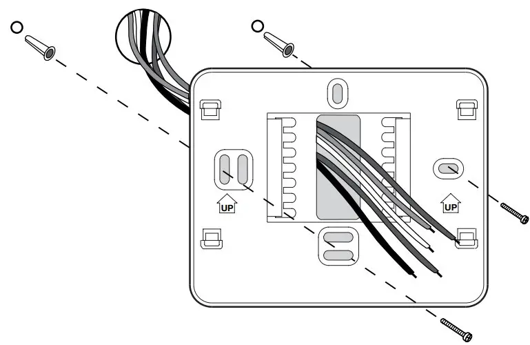
Install the Sub-Base:
- Remove the sub-base from the body of the thermostat.
- Mount the sub-base as shown below:

Drill 3/16” pilot holes in your desired location. Use supplied anchors for drywall or plaster.
Provide Power
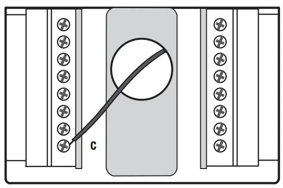
24VAC Power Terminal (C)
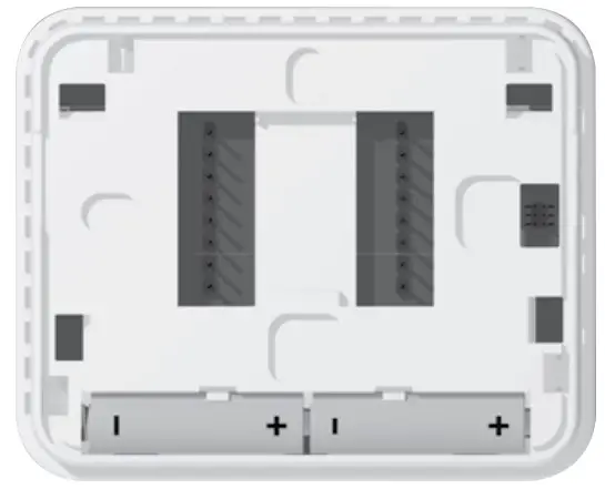
Batteries Installed as Shown
- Battery Power – Insert the 2 supplied “AA” type alkaline batteries into the battery compartment located in the rear housing of the thermostat. Make sure to position the Positive (+) andNegative (-) sides of the batteries correctly with the +/- symbols in the battery compartment.
- Optional 24 Volt AC power – Connect the common side of the transformer to the C terminal on the thermostat sub-base. In dual transformer installations, the transformer common must come from the cooling transformer.
Attach to Thermostat Sub-Base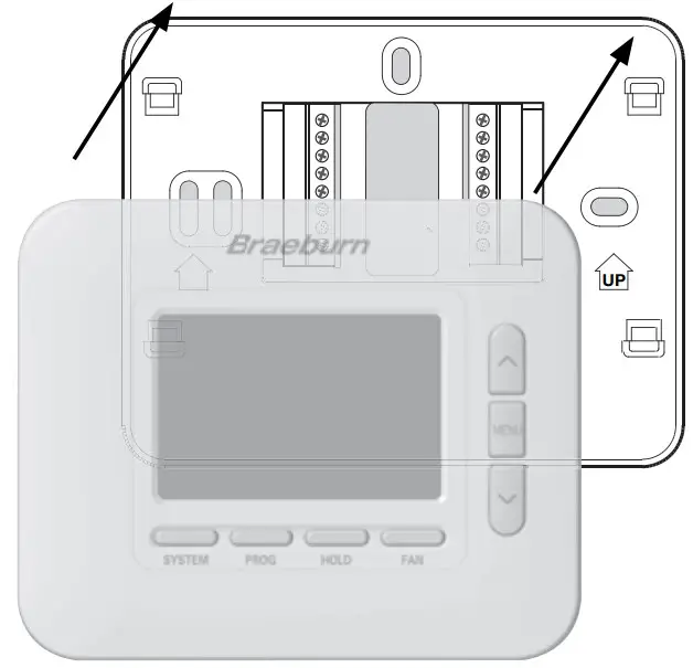
NOTE: This thermostat ships configured as a 1 Heat / 1 Cool conventional (CONV 11) thermostat.
Once you complete the wiring in Section 3, attach thermostat to sub-base and then configure the Installer Settings in Section 5.
- Line up the thermostat body with the sub-base.
- Carefully push the thermostat body against the sub-base until it snaps in place.
WIRING
| Conventional Systems –Typical Wiring Configurations | 4030 / 4235 | 4235 | |||||
| Heat Only or MillivoltSystem Type:CONV 11 | Hydronic Heat OnlySystem Type:HD 1 | Hydronic Heat/CoolSystem Type:HD 11 | 1 Heat/1 CoolSystem Type:CONV 11 | 2 Heat/2 CoolSystem Type:CONV 22 | |||
| Wiring Terminal | Terminal Description | ||||||
| Rh | 24 VAC Heating Transformer | Rh | Rh | Rh1 | Rh1 | Rh1 | |
| Rc | 24 VAC Cooling Transformer | – | – | Rc1,2 | Rc1,2 | Rc1,2 | |
| W1/E | (W1) Conventional Heat Relay(E) Emergency Heat Relay | W1 | W1 | W1 | W1 | W1 | |
| W2/AUX* | (W2) 2nd Stage Conventional Heat (AUX) Heat Pump Auxiliary Heat | – | – | – | – | W2 | |
| Y1 | 1st Stage Compressor Relay | – | – | Y1 | Y1 | Y1 | |
| Y2* | 2nd Stage Compressor Relay | – | – | – | – | Y23 | |
| G | Fan Relay | G3 | G3 | G | G | G | |
| O/B/V3 | (O) Cool Active Reversing Valve(B) Heat Active Reversing Valve (V3) Zone Valve Power Close | – | V33 | V33 | – | – | |
| L | System Malfunction Indicator | – | – | – | – | – | |
| C | 24 VAC Transformer Common | C4 | C4 | C4,5 | C4,5 | C4,5 | |
*4235 Only. “System Type” is configured in the Installer Settings – See section 5.
NOTES – Conventional Systems
- Remove factory installed jumper wire for dual transformer systems
- Only required for dual transformer systems
- Only connect if needed for system
- Optional 24 VAC transformer common connection
- For dual transformer systems, common must come from cooling transformer
Provide disconnect and overload protection as required
Additional Wiring Options
| Wiring Terminal | Terminal Description | Notes |
| S1 | Remote Sensor (Indoor or Outdoor) | These terminals can be used to connect a Braeburn® indooror outdoor remote sensor. For indoor remote sensor configuration, refer to installer setting 23 in section 5. No configuration is required for an outdoor sensor. |
| S2 | ||
| H/D* | (H) Humidification Relay(D) Dehumidification Relay | This terminal can be used to control an external humidifier or dehumidifier relay. Overcooling is also available.For configuration, refer to Installer Settings 25-29 in section 5. |
| DRY1 | Dry Contact Relay (no voltage) | These terminals can be used to connect a condensate overflow monitor, door switch, spring timer or occupancy sensor. For dry contact configuration, refer to Installer Settings 30-32 in section 5. |
| DRY2 |
*4235 Only.
NOTE: Use 18-22 gauge unshielded wire with a 200-foot maximum wire length. Avoid running wire along with 120 VAC wiring or near magnetic ballasts.
| Heat Pump Systems –Typical Wiring Configurations | 4030 / 4235 | 4235 | ||||
| 1 Heat/1 Cool | 2 Heat/1 Cool (w/Aux Heat)System Type: HP 21 | 2 Heat/2 Cool (No Aux Heat)System Type: HP 32 | 3 Heat/2 Cool (w/Aux Heat)System Type: HP 32 | |||
| Wiring Terminal | Terminal Description | Syste HP | m Type: 11 | |||
| Rh | 24 VAC Heating Transformer | Rh1 | Rh1 | Rh1 | Rh1 | |
| Rc | 24 VAC Cooling Transformer | – | – | – | – | |
| W1/E | (W1) Conventional Heat Relay(E) Emergency Heat Relay | – | E2 | – | E2 | |
| W2/AUX* | (W2) 2nd Stage Conventional Heat (AUX) Heat Pump Auxiliary Heat | – | AUX2 | – | AUX2 | |
| Y1 | 1st Stage Compressor Relay | Y1 | Y1 | Y1 | Y1 | |
| Y2* | 2nd Stage Compressor Relay | – | – | Y2 | Y2 | |
| G | Fan Relay | G | G | G | G | |
| O/B/V3 | (O) Cool Active Reversing Valve(B) Heat Active Reversing Valve (V3) Zone Valve Power Close | O/B3 | O/B3 | O/B3 | O/B3 | |
| L | System Malfunction Indicator | L4 | L4 | L4 | L4 | |
| C | 24 VAC Transformer Common | C5 | C5 | C5 | C5 | |
*4235 Only. “System Type” is configured in the Installer Settings – See section 5.
NOTES – Heat Pump Systems
- Do not remove factory installed jumper wire
- If no separate emergency heat relay, connect to AUX and Install a field supplied jumper wire from AUX to E
- O (cool active) or B (heat active) is selected in the Installer Settings – See section 5
- If using optional L terminal, the 24 VAC common must be connected (C terminal)
- Optional 24 VAC transformer common connection
Provide disconnect and overload protection as required
Additional Wiring Options
| Wiring Terminal | Terminal Description | Notes |
| S1 | Remote Sensor (Indoor or Outdoor) | These terminals can be used to connect a Braeburn® indooror outdoor remote sensor. For indoor remote sensor configuration, refer to installer setting 23 in section 5. No configuration is required for an outdoor sensor. |
| S2 | ||
| H/D* | (H) Humidification Relay(D) Dehumidification Relay | This terminal can be used to control an external humidifier or dehumidifier relay. Overcooling is also available.For configuration, refer to Installer Settings 25-29 in section 5. |
| DRY1 | Dry Contact Relay (no voltage) | These terminals can be used to connect a condensate overflow monitor, door switch, spring timer or occupancy sensor. For dry contact configuration, refer to Installer Settings 30-32 in section 5. |
| DRY2 |
*4235 Only.
NOTE: Use 18-22 gauge unshielded wire with a 200-foot maximum wire length. Avoid running wire along with 120 VAC wiring or near magnetic ballasts.
QUICK REFERENCE
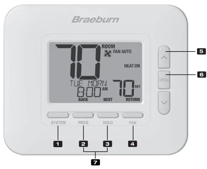
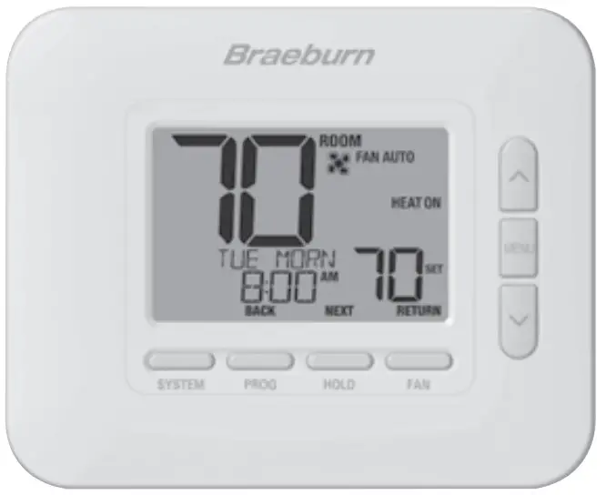
Thermostat
- SYSTEM Button …………………Selects the system you want to control
- PROG Button……………………..Enters programming mode or hold for 3 seconds to enter SpeedSet® mode
BACK Button*……………………Secondary function of the PROG button – Moves to previous setting - HOLD Button……………………..Enters / Exits the HOLD mode (program bypass mode)
NEXT Button* ……………………Secondary function of the HOLD button – Moves to next setting
FAN Button ……………………….Selects the system fan mode - RETURN Button*………………..Secondary function of the FAN button – Exits program or setting modes
- Up / DownArrow Buttons…..Increases or decreases settings (time, temperature, etc.)
- MENU Button…………………….Used to access thermostat User / Installer setting modes
- Lock / Unlock Thermostat…. Access user Lock / Unlock screen by holding PROG and HOLD together for 5 seconds
Battery Compartment………..Located on the back side of thermostat (if installed)
* BACK, NEXT and RETURN are secondary functions of the PROG, HOLD and FAN buttons When in programming or configuration modes, BACK, NEXT and RETURN appear in the display screen indicating that the PROG, HOLD and FAN buttons now function as BACK, NEXT and RETURN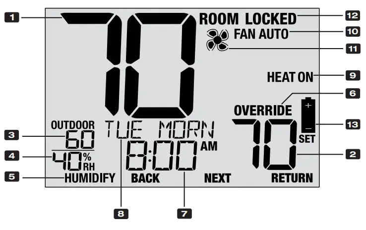
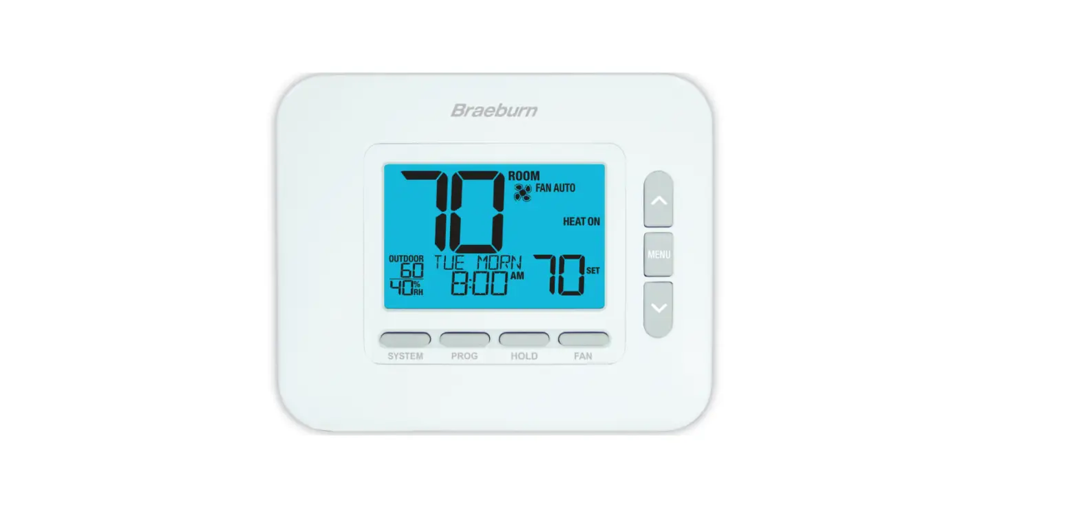
Thermostat Display
- Room Temperature ………………………..Displays the current room temperature
- Set Temperature ……………………………Displays the current setpoint temperature
- Outdoor Temperature …………………….If a Braeburn® outdoor sensor was connected the outdoor temperature will be displayed
- Room Humidity (4235 only) ……………. Displays the current room Relative Humidity level
- Humidity Call Indicator (4235 only) ….Indicates when there is a call for Humidification or Dehumidification (in enabled)
- Override Indicator ………………………… Indicates that the current program schedule has been temporarily overridden
- Time of Day …………………………………. Displays the current time of day
- Message Center …………………………… Displays various thermostat status and maintenance information
- System Mode ………………………………..Displays the system mode and current system status
- Fan Mode Indicator ……………………….Indicates the current system fan mode
- Fan Status Indicator …………………….. Indicates that the system fan is running
- Lock Mode Indicator …………………….. Indicates if the thermostat is locked
- Low Battery Indicator …………………… Indicates when the batteries need to be replaced
INSTALLER SETTINGS
The Installer Settings must be properly configured in order for this thermostat to operate correctly. The Installer Settings are menu driven. The portion of these settings that do not apply to your setup will be skipped.
To Enter Installer Settings Menu
- Press and hold down the MENU button for 5 seconds.
- Release the MENU button after the first installer setting is displayed.
- Change settings as required using the or buttons.
- Press NEXT (HOLD) or BACK (PROG) to move to the next or previous setting.
- Press RETURN (FAN) to exit. Menu will exit automatically after last setting.
*If UNLOCK 0000 is displayed, you must enter your 4-digit installer lock code to proceed (see Installer Settings 39 and 40).
| No. | Installer Setting | Displayed | Default Setting | Available Settings | Description of Available Settings | |||||||||||||||||||||||||
| 1 | Residential or Commercial Profile | MODE | ES | ES | Select for Residential profile | |||||||||||||||||||||||||
| COMM | Select for Commercial profile | |||||||||||||||||||||||||||||
| If residential mode is selected, 4 programming events per day are available (MORN, DAY, EVE, NITE). If commercial profile is selected, 2 programming events per day are available (OCC, UNOC). | ||||||||||||||||||||||||||||||
| 2 | Programming Mode | OG AM DAYS | 7 | 7 | Select for 7-day programming mode | |||||||||||||||||||||||||
| 52 | Select for 5-2 day programming mode | |||||||||||||||||||||||||||||
| O | Select for non-programmable mode | |||||||||||||||||||||||||||||
| [Only available if a Residential (RES) profile was selected in setting 1] Selects the programming capabilities of the thermostat, either full 7 individual days, 5-2 day (weekday/weekend) programming or non-programmable. | ||||||||||||||||||||||||||||||
| 3 | Pre-Occupancy Purge | E U GE | OFF | OFF | Pre-Occupancy Purge is disabled | |||||||||||||||||||||||||
| :15 – 3:00 | Select :15 – 3:00 Pre-Occupancy Purge | |||||||||||||||||||||||||||||
| [Only available if a Commercial (COMM) profile was selected in setting 1] Selects the amount of time the system fan will run before the start of the Occupied (OCC) program period (15 minute increments). | ||||||||||||||||||||||||||||||
| 4 | Clock Format | CLOCK | 12H | 12H | Select for a 12-hour clock | |||||||||||||||||||||||||
| 24H | Select for a 24-hour clock | |||||||||||||||||||||||||||||
| Selects either a 12 hour or 24 hour clock format. | ||||||||||||||||||||||||||||||
| 5 | Temperature Scale | DEG EE | F | F | Select for Fahrenheit temperature display | |||||||||||||||||||||||||
| C | Select for Celsius temperature display | |||||||||||||||||||||||||||||
| Selects a temperature scale of either °F or °C. | ||||||||||||||||||||||||||||||
| 6 | Auto Changeover | AUTO C G | OFF | OFF | Auto-Changeover disabled | |||||||||||||||||||||||||
| O | Auto-Changeover enabled | |||||||||||||||||||||||||||||
| When auto-changeover mode is enabled and selected, the system can automatically switch between heating and cooling modes. There is a 5 minute delay when switching modes if auto changeover is selected. | ||||||||||||||||||||||||||||||
| 7 | Auto Changeover Dead Band | DEADBA D | 3 | 2, 3, 4, 5 | Select an Auto Changeover Dead Band of 2°, 3°, 4° or 5˚ F (1°, 1.5°, 2° or 2.5° C) | |||||||||||||||||||||||||
| [Only available if Auto Changeover was enabled in setting 6] When using auto changeover mode, the dead band is a forced separation between the heating and cooling setpoints so that the systems do not work against each other.This setting selects the amount of this dead band in degrees. If using the dehumidification overcooling feature in setting 28, the allowable deadband will be limited based on your dehumidification overcooling limit selection. | ||||||||||||||||||||||||||||||
| 8 | System Type | SYSTEM | CO V 11 | CO V 11 | Select for 1H/1C Conventional system | |||||||||||||||||||||||||
| CO V 22 | Select for 2H/2C Conventional system (4235) | |||||||||||||||||||||||||||||
| H 11 | Select for 1H/1C Heat Pump system | |||||||||||||||||||||||||||||
| H 21 | Select for 2H/1C Heat Pump system | |||||||||||||||||||||||||||||
| H 32 | Select for 3H/2C Heat Pump system (4235) | |||||||||||||||||||||||||||||
| HD 1 | Select for heat-only Hydronic system | |||||||||||||||||||||||||||||
| HD 11 | Select for Hydronic system with cooling | |||||||||||||||||||||||||||||
| Select the type of equipment you are controlling. The HP 32 system type is for a 2-stage heat pump compressor (stage 1 and 2) with auxiliary heat (stage 3). System types CONV 22 and HP 32 are not available in model 4030. | ||||||||||||||||||||||||||||||
| 9 | 1st Stage Differential | DEG EE DIF1 | 0.5 | 0.5, 1.0, 2.0 | Select a 1st stage temperature differential of 0.5°, 1° or 2° F (0.2°, 0.5° or 1.0° C) | |||||||||||||||||||||||||
| Selects a 1st stage temperature differential which controls the degree of separation between the setpoint temperature and the 1st stage of heating or cooling. | ||||||||||||||||||||||||||||||
| 10 | 2nd Stage Differential | DEG EE DIF2 | 2.0 | 1.0, 2.0, 3.04.0, 5.0, .0 | Select a 2nd stage temperature differential of 1°, 2°, 3°, 4°, 5° or 6° F (0.5°, 1.0°, 1.5°, 2.0°, 2.5° or 3.0° C) | |||||||||||||||||||||||||
| [Only available if a 2 or 3 stage system was selected in setting 8] Selects a 2nd stage temperature differential which controls the degree of separation between the 1st and 2nd stage of heating or cooling. | ||||||||||||||||||||||||||||||
| 11 | 3rd Stage Differential | DEG EE DIF3 | 2.0 | 1.0, 2.0, 3.04.0, 5.0, .0 | Select a 3rd stage temperature differential of 1°, 2°, 3°, 4°, 5° or 6° F (0.5°, 1.0°, 1.5°, 2.0°, 2.5° or 3.0° C) | |||||||||||||||||||||||||
| [Only available if a 3 stage system was selected in setting 8] Selects a 3rd stage temperature differential which controls the degree of separation between the 2nd and 3rd stage of heating. | ||||||||||||||||||||||||||||||
| 12 | Conventional Heat Fan Control | FA 1 | GAS | GAS | Select for conventional Gas heating | |||||||||||||||||||||||||
| ELEC | Select for conventional Electric heating | |||||||||||||||||||||||||||||
| [Only available if a conventional system was selected in setting 8] Selects a 1st stage fan control of either gas or electric heat. If Electric is selected, the thermostat turns on the system fan with a call for heating. | ||||||||||||||||||||||||||||||
| 13 | Emergency Heat Fan Control | EME FA | ELEC | ELEC | Select for Electric Emergency Heat | |||||||||||||||||||||||||
| GAS | Select for Gas Emergency Heat | |||||||||||||||||||||||||||||
| [Only available if a 2 or 3 stage heat pump system was selected in setting 8] Selects emergency heat fan controlof either gas or electric heat. If Electric is selected, the thermostat turns on the system fan with a call for emergency heat. | ||||||||||||||||||||||||||||||
| 14 | Finish with High Stage | AUX F SH | O | 0 | Finish with High Stage is disabled | |||||||||||||||||||||||||
| YES | Finish with High Stage is enabled | |||||||||||||||||||||||||||||
| [Only available if a 2 or 3 stage system was selected in setting 8] When Finish with High Stage is enabled, once engaged, the supplemental heat source (2nd or 3rd stage) will remain on until temperature is satisfied. When disabled, these supplemental heat source(s) will turn off approximately 0.5 degrees before setpoint to let the 1st stage heat source complete the heat call. | ||||||||||||||||||||||||||||||
| 15 | Reversing Valve (O/B Terminal) | VALVE | 0 | 0 | Select for cool active Reversing Valve | |||||||||||||||||||||||||
| B | Select for heat active Reversing Valve | |||||||||||||||||||||||||||||
| [Only available if a heat pump system was selected in setting 8] Selects the output state of the O/B terminal. Select O for this terminal to be active in the cool mode or select B for this terminal to be active in the heat mode. | ||||||||||||||||||||||||||||||
| 16 | Fossil Fuel Backup Heat | AUX HEAT | ELEC | ELEC | Select for Electric Auxiliary heat (with compressor) | |||||||||||||||||||||||||
| GAS | Select for Gas Auxiliary heat (without compressor) | |||||||||||||||||||||||||||||
| [Only available if a 2 or 3 stage heat pump system was selected in setting 8] When set to electric, both the compressor and auxiliary stage will run when a call for auxiliary heat is made. When set to gas, the compressor stage(s) will be locked out one minute after a call for auxiliary heat. This setting can be overridden if setting an auxiliary heat balance point in setting 34. | ||||||||||||||||||||||||||||||
| 17 | Compressor Power Outage Protection | C O | OFF | 0FF | Power outage lockout delay is disabled | |||||||||||||||||||||||||
| 0 | Power outage lockout delay is enabled | |||||||||||||||||||||||||||||
| [Only available if a heat pump system was selected in setting 8 and thermostat is powered with a 24 VAC common (C) wire] When enabled, this thermostat will provide cold weather compressor protection by locking out the compressor stage(s) of heating for a period of time after a power outage greater than 60 minutes. | ||||||||||||||||||||||||||||||
| 18 | AC Power Interrupt Warning | OW MO | OFF | OFF | AC Power Interrupt Warning is disabled | |||||||||||||||||||||||||
| O | AC Power Interrupt Warning is enabled | |||||||||||||||||||||||||||||
| [Only available if thermostat is powered with a 24 VAC common (C) wire] When enabled, the thermostat will display NO POWER when AC power to the thermostat is lost. Batteries must also be installed for this feature to operate. | ||||||||||||||||||||||||||||||
| 19 | Compressor Short Cycle Protection (CSCP) | CSC MI | 5 | 5, 4, 3,2, 1, 0 | Select CSCP delay duration in minutes | |||||||||||||||||||||||||
| Selects the number of minutes the compressor(s) will be locked out after turning off. This delay will run simultaneously with any delay built into the equipment. | ||||||||||||||||||||||||||||||
| 20 | Residual Cooling Fan Delay | ESIDUAL COOL | 0 | 0, 0,30, 0 | Select fan delay duration in seconds | |||||||||||||||||||||||||
| Selects a delay for the system fan after the cooling compressor has turned off. This delay will help remove the remaining cool air out of the ductwork providing additional efficiency. | ||||||||||||||||||||||||||||||
| 21 | Circulating Fan Lock | CI CLOCK | OFF | OFF | Circulating Fan Lock is disabled | |||||||||||||||||||||||||
| O | Circulating Fan Lock is enabled | |||||||||||||||||||||||||||||
| [Not available if 1 HD was selected in setting 8] When enabled, the only user fan settings available are ON and CIRC (Circulation). The AUTO and PROG fan settings are not available with this setting enabled. | ||||||||||||||||||||||||||||||
| 22 | Adaptive Recovery Mode (ARMTM) | ECOVE | OFF | OFF | Adaptive Recovery Mode is disabled | |||||||||||||||||||||||||
| O | Adaptive Recovery Mode is enabled | |||||||||||||||||||||||||||||
| [Not available if non-programmable was selected in setting 2] During ARM, room temperature is recovered by turning on the heating or cooling up to 3-hours before the end of the set back period. The setpoint temperature is changed to that of the upcoming program temperature. | ||||||||||||||||||||||||||||||
| 23 | Indoor Remote Sensor | EMOTE SE S | I | I | Temperature is sensed from thermostat only (Internal) | |||||||||||||||||||||||||
| E | Temperature is sensed from remote sensor only (External) | |||||||||||||||||||||||||||||
| A | Temperature is averaged between thermostat and remote sensor (Average) | |||||||||||||||||||||||||||||
| [Only available if Braeburn model 5390 remote indoor sensor is connected] If a Braeburn indoor remote sensor is connected, the thermostat will automatically detect the sensor. When an indoor sensor is detected, you may select between thermostat only (1), remote sensor only (E) or the average of the thermostat and remote sensor (A). | ||||||||||||||||||||||||||||||
| 24 | User Lock Security Level | USE LOCK LVL | 3 | 3 | If locked, all buttons are disabled | |||||||||||||||||||||||||
| 2 | If locked, all buttons except and are disabled | |||||||||||||||||||||||||||||
| 1 | If locked, only the PROG, HOLD and MENU buttons are disabled | |||||||||||||||||||||||||||||
| Selects the level of keypad lockout when the thermostat has been locked by the user. See the User Manual for instructions on setting the 3-digit lock code and locking/unlocking the thermostat. | ||||||||||||||||||||||||||||||
| 25 | Humidification (4235 only) | HUMID | OFF | OFF | Humidification is disabled | |||||||||||||||||||||||||
| DE | Dependent humidification is enabled | |||||||||||||||||||||||||||||
| I D | Independent humidification is enabled | |||||||||||||||||||||||||||||
| For use with an external humidifier. Select between disabling humidification, dependent control or independent control.The DEP setting controls humidification only during a call for heating. The IND setting allows humidification output in the heat mode, but does not require a call for heating. It is recommended that the IND setting only be used with systems designed for low air temperature humidification such as steam humidification. Always ensure the heat exchanger or other system parts are not exposed to excess water from condensation or other sources. When there is any doubt, use the OFF or DEP setting. | ||||||||||||||||||||||||||||||
| 26 | Auto Humidity Set Point Limit (4235 only) | HUMID | MA | MA | Maximum humidity setpoint is not limited | |||||||||||||||||||||||||
| AUTO | Maximum humidity setpoint is limited based on outdoor temperature | |||||||||||||||||||||||||||||
| [Only available if Braeburn® model 5490 remote outdoor sensor is connected] When AUTO is selected, the humidity setpoint maximum is limited based on the outdoor temperature. Selecting MAN allows you to manually control thelevel of humidity between 10% and 50%. | ||||||||||||||||||||||||||||||
| 27 ‘ | Dehumidification (4235 only) | DEHUMID | OFF | OFF | Dehumidification is disabled | |||||||||||||||||||||||||
| DE | Dependent dehumidification is enabled | |||||||||||||||||||||||||||||
| I D | Independent dehumidification is enabled | |||||||||||||||||||||||||||||
| [IND (independent) dehumidification is not available if Humidification was enabled in setting 25] (DEP) If the humidity level is above the humidity setpoint, cooling stays on until the humidity level drops below the setpoint or when the over cooling limit in setting 28 is reached in. (IND) For use with an external dehumidifier – When the humidity level rises above the dehumidification setpoint, both the G (Fan) and D terminals are activated. Not available in 1HD system mode. | ||||||||||||||||||||||||||||||
| 28 | Dehumidification Overcooling Limit (4235 only) | OVE COOL LIM | 1.0 | 1.0°, 2.0°,or 3.0° F(.5°, 1.0°,or 1.5° C) | Select a dehumidification overcooling limit in degrees | |||||||||||||||||||||||||
| [Only available if dependent dehumidification (DEP) was selected in setting 27] Select the number of degrees the system is allowed to over cool while attempting to reduce humidity. This setting will affect the maximum allowable deadband set in setting 7. | ||||||||||||||||||||||||||||||
| 29 | Dehumidification (D) Terminal Output (4235 only) | DH ELAY | :0 | :0 | Select a normally open relay | |||||||||||||||||||||||||
| :C | Selects a normally closed relay | |||||||||||||||||||||||||||||
| [Only available if independent dehumidification (IND) was selected in setting 27] Select normally open relay (N:O) or normally closed (N:C) relay for D terminal output in independent dehumidification mode. This setting can also be used for dehumidification fan speed control. | ||||||||||||||||||||||||||||||
| 30 | Dry Contact Type | CO TACT | OFF | OFF | Dry contact is disabled | |||||||||||||||||||||||||
| CO D | Select for condensate overflow monitoring | |||||||||||||||||||||||||||||
| DOO | Select for door open monitoring | |||||||||||||||||||||||||||||
| OCC | Select for occupancy monitoring | |||||||||||||||||||||||||||||
| [If a Residential profile was selected in setting 1, only the condensate (COND) setting will be available] The dry contact can be used to monitor several conditions. See the table below for an outline of these conditions. WARNING: DRY1, DRY2 terminals are a dry contact relay and should never have voltage applied to them. If not using the dry contact, make sure to select OFF for this setting. | ||||||||||||||||||||||||||||||
| Detailed Description of Dry Contact Settings (Installer Setting 30) | |||||||||||||||
| Condensate | CO D | This setting is intended for a condensate pan overflow monitor. When the contact is active, the thermostat will immediately disable the cooling compressor(s) and display the message OVERFLOW. After the contact is inactive for 1 minute, the compressor(s) will resume operation and the thermostat display will return to normal. | |||||||||||||
| Door Switch | DOO | This setting is intended for a door switch monitor. When this mode is selected, the thermostat will only run the occupied (OCC) portion of the program schedule while the contact is inactive (door closed). When the contact becomes active (door open), the thermostat will turn OFF and display the message DOOROPEN until the contact becomes inactive again. There is a 3-minute delay before the thermostat turns OFF. Temperature override is not permitted while the contact is active (door open). | |||||||||||||
| Occupancy | OCC | This setting is intended for the use of an occupancy sensor or mechanical spring-wound timer switch. When active, the thermostat will be forced into the occupied (OCC) portion of the program schedule until the contact becomes inactive. In setting 32 below, the Occupancy Trigger Controlcan be selected (PROG or UNOC). | |||||||||||||
| 31 | Dry Contact Relay State | CO TACT | :0 | :0 | Selects a normally open relay | ||||||||||
| :C | Selects a normally closed relay | ||||||||||||||
| [Not available if OFF was selected in setting 30] Select normally open (N:O) or normally closed (N:C) for the dry contact relay terminals (DRY1, DRY2). | |||||||||||||||
| 32 | Occupancy Trigger Control | OCCU IED | OG | OG | Follows current program schedule until the occupied state is triggered | ||||||||||
| U OC | Follows the unoccupied (UNOC) program schedule until the occupied state is triggered | ||||||||||||||
| [Only available if occupancy monitoring (OCC) was selected in setting 30] If the dry contact type was set to occupied (OCC) in setting 30, there will be 2 selections for the occupied state. If PROG is selected (default), the thermostat will follow its normal program schedule until the dry contact is active. When the dry contact is active, the thermostat will only operatethe occupied portion of the program schedule and ignore the unoccupied portion of the program schedule. If UNOC is selected, the thermostat will ignore the program schedule and always operate in the unoccupied state. When the dry contact is active, the thermostat will operate in the occupied state for the duration of the contact being active. | |||||||||||||||
| 33 | Compressor Balance Point | BAL OI T COM | O | O | Compressor balance point is disabled | ||||||||||
| 0 to 50(-18˚ to 10˚C) | Select a Compressor Balance Point of 0˚ to 50˚ (-18˚ to 10˚C) | ||||||||||||||
| [Only available for 2 or 3 stage heat pump systems with a Braeburn® 5490 outdoor sensor connected] Locks out the use of the heat pump compressor’s heat stage(s) when the outside air temperature is less than the selected setting. During this lockout period, only the auxiliary heat stage will operate. | |||||||||||||||
| 34 | Auxiliary Heat Balance Point | BAL OI T AUX | O | O | Auxiliary heat balance point is disabled | ||||||||||
| 70 to 40(21 ˚ to 4˚C) | Select a Auxiliary Heat Balance Point of 70° to 40°F (21° to 4°C) | ||||||||||||||
| [Only available for 2 or 3 stage heat pump systems with a Braeburn 5490 outdoor sensor connected] Locks out the use of the auxiliary heat stage when the outside air temperature exceeds the selected setting. This balance point overrides the fossil fuel compressor lockout in setting 16. If setting 16 is set to gas and the outdoor temperature is over the auxiliary balance point, the compressor will remain on during a call for auxiliary heat. | |||||||||||||||
| 35 | Heat Setpoint Upper Limit | HIGH LIM HEAT | 0 | 0 – 45(32˚ to 7˚C) | Select a Heat Setpoint Upper Limit of 90° to 45°F (32° to 7°C) | ||||||||||
| Selects the upper setpoint adjustment limit that cannot be exceeded in heat mode. | |||||||||||||||
| 36 | Heat Setpoint Lower Limit | LOW LIM HEAT | 45 | 45 – 0(7˚ to 32˚C) | Select a Heat Setpoint Lower Limit of 45° to 90°F (7° to 32°C) | ||||||||||
| Selects the lower setpoint adjustment limit that cannot be exceeded in heat mode. | |||||||||||||||
| 37 | Cool Setpoint Lower Limit | LOW LIM COOL | 45 | 45 – 0(7˚ to 32˚C) | Select a Cool Setpoint Lower Limit of 45° to 90°F (7° to 32°C) | ||||||||||
| [Not available for heat-only hydronic systems] Selects the lower setpoint adjustment limit that cannot be exceeded in cool mode. | |||||||||||||||
| 38 | Cool Setpoint Upper Limit | HIGH LIM COOL | 0 | 0 – 45(32˚ to 7˚C) | Select a Cool Setpoint Upper Limit of 90° to 45°F (32° to 7°C) | ||||||||||
| [Not available for heat-only hydronic systems] Selects the upper setpoint adjustment limit that cannot be exceeded in cool mode. | |||||||||||||||
| 39 | Installer Lock | I STLOCK | O | O | Installer Lock disabled | ||||||||||
| YES | Installer Lock enabled | ||||||||||||||
| When enabled, a 4-digit lock code can be entered in setting 40. This lock code will be required the next time the Installer Settings menu is accessed. Select NO to skip the installer lock. | |||||||||||||||
| 40 | Installer Lock Code | IL CODE | 0000 | 0- | Select 0-9 for each digit | ||||||||||
| [Only available if Installer Lock was enabled in setting 39] Select a 4-digit lock code (0-9 for each digit) to lock the Installer Settings menu. The code 0000 is not a valid lock code and cannot be used. | |||||||||||||||
| 41 | Installer Clear (factory reset) | CLEA | O E | O E | Clear disabled – No changes made | ||||||||||
| ALL | Clear enabled – Factory Reset | ||||||||||||||
| Selecting ALL will return thermostat to all factory default settings. Factory reset will take affect upon exiting Installer settings menu. | |||||||||||||||
Additional options such as Service Monitors, setting the lock code, etc. are located in the User Settings – See User Manual.
SYSTEM TESTING
![]() Warning Read Before Testing
Warning Read Before Testing
- Do not short (or jumper) across terminals on the gas valve or at the heating or cooling system control board to test the thermostat installation. This could damage the thermostat and void the warranty.
- Do not select the COOL mode of operation if the outside temperature is below 50º F (10º C). This could possibly damage the controlled cooling system and may cause personal injury.
- This thermostat includes an automatic compressor protection feature to avoid potential damage to the compressor from short cycling. When testing the system, make sure to take this delay into account.
NOTE: The compressor delay can be bypassed by adjusting Installer Setting 19 – See section 4.
- Press the SYSTEM button until the thermostat is in HEAT mode.
- Press the button to raise the set temperature a minimum of 3 degrees above the current room temperature. The system should start within a few seconds. With a gas heating system, the fan may not start right away.
- Press the SYSTEM button until the thermostat is in the OFF mode. Allow the heating system to fully shut down.
- Press the SYSTEM button until the thermostat is in the COOL mode.
- Press the button to lower the set temperature a minimum of 3 degrees below the current room temperature. The system should start within a few seconds (unless compressor short cycle protection is active – See note above).
- Press the SYSTEM button until the thermostat is in the OFF mode. Allow thcooling system to fully shut down.
- Press the FAN button until the thermostat is in FAN ON mode. The system fan should start within a few seconds.
- Press the FAN button until the thermostat is in FAN AUTO mode. Allow the system fan to turn off.
- If the thermostat is controlling auxiliary equipment such as a humidifier, adjust settings to test these devices.
Limited Warranty


When installed by a professional contractor, this product is backed by a 5 year limited warranty. Limitations apply. For limitations, terms and conditions, you may obtain a full copy of this warranty:
- Visit us online: www.braeburnonline.com/warranty
- Call us:
866.268.5599 - Write us:
Braeburn Systems LLC
2215 Cornell Avenue
Montgomery, IL 60538
Installer – store this manual for future reference
![]()
Braeburn Systems LLC
2215 Cornell Avenue • Montgomery, IL 60538
Technical Assistance: www.braeburnonline.com
Call us toll-free: 866-268-5599 (U.S.)
630-844-1968 (Outside the U.S.)
©2022 Braeburn Systems LLC • All Rights Reserved


