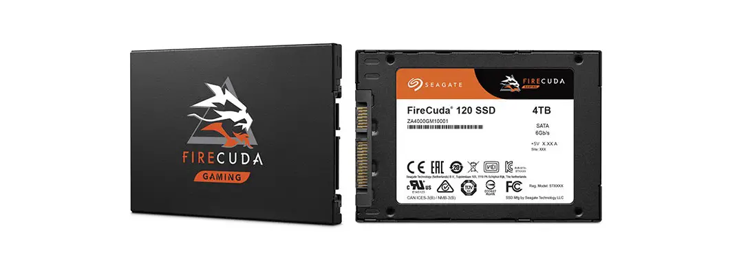
SEAGATE FireCuda 120 SSD Perfect for Gaming Use and Video Editing Owner’s Manual
Introduction
| Feature | Description | |||
| Capacity (User) | 500 GB, 1000 GB, 2000 GB, 4000 GB | |||
| Certifications, Eco-Compliance | CE, UL, FCC, BSMI, KCC, Microsoft WHCK, VCCI, CBn RoHS | |||
| Dimensions | (69.85±0.25) x (100±0.25) x (Max. 7) mm | SSD outer case can support suitable Z-height for various host situations. | ||
| Endurance |
| Endurance rating valid for SSD Life Remaining > 1% (SMART E7h>1).See Section 2.5, Reliability/Endurance. | ||
| Form Factor | 2.5-inch Standard SSD | |||
| Interface Compliance |
| |||
| NAND | 3D TLC | |||
| Operating Systems |
| |||
| Performance Random |
| Actual performance might vary depending on use conditions and environment.See Section 2.2, Performance. | ||
| Performance Sequential |
| Actual performance might vary depending on the capacity, use conditions and environment.See Section 2.2, Performance. | ||
| Power Consumption |
| Based on 4000 GB SSD. Results vary with capacity and mode. | ||
| Power Loss Data Protection |
| |||
| Power Management |
| |||
| Reliability | End-to-end data path protectionn MTBF: 1.8 million hoursn UBER: 1 error in 1016 bits read | |||
| Shock and Vibration | Shockn Non-Operating: 1,500 G, at 0.5 ms | See Section 2.4, Environmental Conditions. | ||
| Vibrationn Non-Operating: 1.52 GRMS, (20 to 80 Hz, Frequency) | ||||
| Temperature Range (Operating) | 0°C to 70°Cn Temperature Sensor (SMART Attribute ID C2h) | |||
| Voltage | 5V±5% | |||
| Warranty | Five years, or when the device reaches Host TBW, whichever happens first. Endurance rating valid for SSD Life Remaining > 1% (SMART E7h>1). | |||
| Weight | 50 g, 1.76 Oz ±5% | |||
Specifications
Models and Capacity
Table 2 Models and Capacity
| Model Names | User Capacity |
| ZA500GM10001 | 500 GB |
| ZA1000GM10001 | 1000 GB |
| ZA2000GM10001 | 2000 GB |
| ZA4000GM10001 | 4000 GB |
NOTE: About capacity:
- Sector Size: 512 Bytes
- User-addressable LBA count = ((97696368) + (1953504 x (Desired Capacity in Gb-50.0)) From International Disk Drive Equipment and Materials Association (IDEMA) (LBA1-03_standard.doc)
Performance
Table 3 Random and Sequential Read and Write Performance
| Parameter | 500 GB | 1000 GB | 2000 GB | 4000 GB |
| Sequential Read MB/s | 560 MB/s | 560 MB/s | 560 MB/s | 560 MB/s |
| Sequential Write MB/s | 540 MB/s | 540 MB/s | 540 MB/s | 540 MB/s |
| Random Read (IOPS) | 100,000 | 100,000 | 100,000 | 100,000 |
| Random Write (IOPS) | 90,000 | 90,000 | 90,000 | 90,000 |
NOTE: About performance:
- Fresh out of box (FOB) performance obtained on newly formatted drive. Performance may vary based on the SSD’s firmware version, system hardware, and configuration.
- Performance is based on CrystalDiskMark v.6.0.0 ×64 on Windows 10 host.
Power Consumption
Table 4 Power Consumption
| 500 GB | 1000 GB | 2000 GB | 4000 GB | |
| Read (mW) | 2300 | 2400 | 2600 | 2800 |
| Write (mW) | 2300 | 2400 | 2600 | 2800 |
| Idle (mW) | 120 | 135 | 140 | 150 |
| Slumber (mW) | 35 | 55 | 60 | 65 |
| DEVSLP (mW) | 5 | 5 | 5 | 5 |
NOTE: About power consumption:
- The average value of power consumption is based on 100% conversion efficiency.
- The measured power voltage is 5 V.
- Measured under ambient temperature.
- Sequential Read/Write is measured while testing 4000 MB five times by CrystalDiskMark.
- Power Consumption can differ according to flash configuration and platform.
Environmental Conditions
Table 5 Temperature, Humidity, Shock
| Specification | Value |
| Temperature Operating (case temperature at specific airflow) Non-operating | 0°C to 70°C -40°C to 85°C |
| Humidity Operating Non-operating (storage) | 90% 93% |
| Shock Non-operating | 1,500 G, duration 0.5 ms |
| Vibration Non-operating | 1.52 GRMS, (20Hz to 80Hz, Frequency) |
NOTE: Temperature is measured without condensation. Operating mode temperature is measured by temperature sensor, SMART Attribute C2h.
NOTE: Shock and vibration results assume that the SSD is mounted securely with the input vibration applied to the SSD mounting. These specifications do not cover connection issues that may result from testing at this level. The measured specification is in root mean square (RMS) form.
- Non-operating Shock. The limits of non-operating shock applies to all conditions of handling and transportation. This includes both isolated SSD and integrated SSDs. Shock may be applied in the X, Y, or Z-axis.
- Non-Operating Vibration. The limits of non-operating vibration shall apply to all conditions of handling and transportation. This includes both isolated SSD and integrated SSDs. Vibration may be applied in the X, Y, or Z-axis.
Reliability/Endurance
Table 6 Reliability/Endurance
| Specification | Value |
| Mean time between failures (MTBF) | 1.8 million hours |
| Bit Error Rate | 1 error in 1016 bits read |
| Endurance |
|
NOTE: About endurance
- The SSD achieves the specified MTBF in an operational environment that complies with the operational temperature range specified in this manual. Operating temperatures are measured by temperature sensor, SMART Attribute ID C2h.
- Endurance rating valid for SSD Life Remaining > 1% (SMART E7h>1).
- Endurance is characterized while running Client JESD219A workload (per JESD218A specification).
Mechanical Information
Dimensions and Weight
- Weight: 50 g, 1.76 Oz +/- 5%
- Height: Maximum, 7 mm+0.10/-0.30
- Width: 69.85 mm±0.25 mm
- Length: 100.10 mm±0.25 mm
Figure 1 FireCuda 120 SSD Enclosure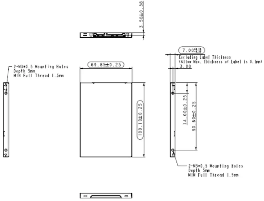
Figure 2 FireCuda 120 SSD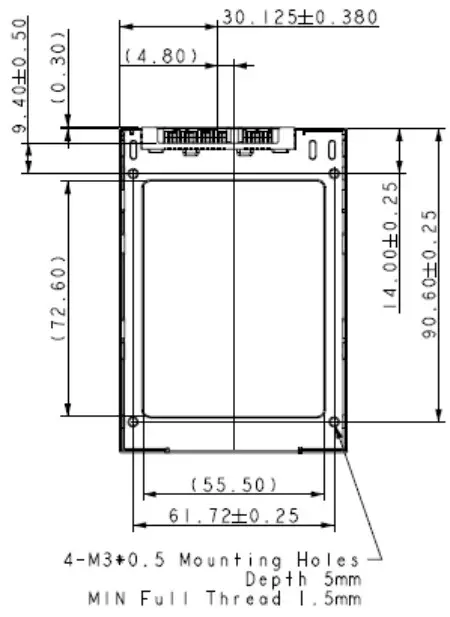
Pin and Signal Descriptions
Signal Pin Definitions
Table 7 Serial ATA Connector Pin Signal Definitions
| Pin | Name | Definition |
| S1 | Ground | Ground |
| S2 | A+ | Differential signal pair A+ and A- |
| S3 | A- | |
| S4 | Ground | Ground |
| S5 | B- | Differential signal pair B- and B+ |
| S6 | B+ | |
| S7 | Ground | Ground |
NOTE Key and spacing separate the signal and power segments.
Power Pin Definitions
Table 8 Power Pin Definitions
| Pin | Function | Definition |
| P1 | not used | Not Used (3.3 V) |
| P2 | V33 | Not Used (3.3 V) |
| P3 | DEVSLP | SATA PHY Power Control |
| P4 | GND | Ground |
| P5 | GND | Ground |
| P6 | GND | Ground |
| P7 | V5 | 5 V Power, Precharge |
| P8 | V5 | 5 V Power |
| P9 | V5 | 5 V Power |
| P10 | GND | Ground |
| P11 | Reserved | Reserved |
| P12 | GND | Ground |
| P13 | not used | Not Used (12 V pre-charge) |
| P14 | V12 | Not Used (12 V) |
| P15 | V12 | Not Used (12 V) |
NOTE: About Power Pin Signal Definitions:
- Key and spacing separate the signal and power segments.
- Uses 5 V power only; 3.3 V (P1-P2) and 12 V (P13-P15) power are not used.
Supported ATA Command List
The FireCuda 120 SSD complies with ATA-8/ACS-3. All mandatory and many optional commands and features are supported.
ATA Feature Set
The following table summarizes the ATA feature set and commands that the FireCuda 120 SSD supports.
Table 9 ATA Feature Set
| Feature | Supported |
| 48-Bit Address feature set | Yes |
| General feature set | Yes |
| Native Command Queuing (NCQ) feature set | Yes |
| Power Management feature set | Yes |
| Security feature set | Yes |
| SMART feature set | Yes |
ATA Command Description
The following table shows the ATA commands supported
Table 10 ATA Command Description
| Op-Code | Support | Command Description | Op-Code | Support | Command Description | |||
| 00h | Y | NOP | B6h | 12h | — | — | NV Cache: QUERY NV CACHE PINNED SET DMA EXT | |
| 03h | — | CFA Request Extended Error | B6h | 13h | — | NV Cache: QUERY NV CACHE MISSES DMA EXT | ||
| 06h | Y | Data Set Management | B6h | 14h | — | — | NV Cache: FLUSH NV CACHE | |
| 08h | — | Device Reset | C4h | — | — | Y | Read Multiple | |
| 0Bh | — | Request Sense Data EXT | C5h | — | — | Y | Write Multiple | |
| 10h | Y | Recalibrate | C6h | — | — | Y | Set Multiple Mode | |
| 11h to 1Fh | — | Recalibrate | C7 | — | — | Read DMA Queued | ||
| 20h | Y | Read Sectors | C8h | — | — | Y | Read DMA | |
| 21h | Y | Read Sectors without Retry | 9h | — | — | — | Read DMA Without Retry | |
| 22h | — | Read Long | CAh | — | — | Y | Write DMA | |
| 23h | — | Read Long Without Retry | CBh | — | — | Y | Write DMA Without Retry | |
| 24h | Y | Read Sectors EXT | CCh | — | — | — | Write DMA Code | |
| 25h | Y | Read DMA EXT | CDh | — | — | — | CFA Write Multiple Without Erase | |
| 26h | — | — | Read DMA Queued EXT | CEh | — | — | Y | Write Multiple FUA EXT |
| 27h | — | Y | Read Native Max Address EXT | D1h | — | — | — | Check Media Card Type |
| 29h | — | Y | Read Multiple EXT | DAh | — | — | — | Get Media Status |
| 2Ah | — | — | Read Stream DMA EXT | DEh | — | — | — | Media Lock |
| 2Bh | — | — | Read Stream EXT | DFh | — | — | — | Media Unlock |
| 2Fh | — | Y | Read Log EXT | E0h | — | — | Y | Standby Immediate |
| 30h | — | Y | Write Sectors | E1h | — | — | Y | Idle Immediate |
| 31h | — | Y | Write Sectors without Retry | E2h | — | — | Y | Standby |
| 32h | — | — | Write Long | E3h | — | — | Y | Idle |
| 33h | — | — | Write Long Without Retry | E4h | — | — | Y | Read Buffer |
| 34h | — | Y | Write Sectors EXT | E5h | — | — | Y | Check Power Mode |
| 35h | — | Y | Write DMA EXT | E6h | — | — | Y | Sleep |
| 36h | — | Write DMA Queued EXT | E7h | — | — | Y | Flush Cache | |
| 37h | — | Y | Set Max Address EXT | E8h | — | — | Y | Write Buffer |
| 38h | — | — | CFA Write Sectors Without Erase | E9h | — | — | Y | Read Buffer DMA |
| 39h | — | Y | Write Multiple EXT | EAh | — | — | Y | Flush Cache EXT |
| 3Ah | — | — | Write Stream DMA EXT | EBh | — | — | Y | Write Buffer DMA |
| 3Bh | — | — | Write Stream EXT | ECh | — | — | Y | Identify Device |
| 3Ch | — | — | Write Verify | EDh | — | — | — | Media Eject |
| 3Dh | — | Y | Write DMA FUA EXT | EEh | — | — | — | Identify Device DMA |
| 3Eh | — | — | Write DMA Queued FUA EXT | EFh | 01h | — | — | Set Features: Enable 8-bit PIO Transfer Mode (CFA feature set only) |
| 3Fh | — | Y | Write Log EXT | EFh | 02h | — | Y | Set Features: Enable Write Cache |
| 40h | — | Y | Read Verify Sectors | EFh | 03h | — | Y | Set Features: Set transfer mode based on value in Count field. |
| 41h | — | Y | Read Verify Sectors without Retry | EFh | 05h | — | — | Set Features: Enable advanced power man- agement. |
| 42h | — | Y | Read Verify Sector(s) EXT | EFh | 06h | — | — | Set Features: Enable Power-Up In Standby fea- ture set. |
| 44h | — | — | Reserved | EFh | 07h | — | — | Set Features: Power-Up In Standby feature set device spin-up. |
| 45h | — | O | Write Uncorrectable EXT | EFh | 0Ah | — | — | Set Features: Enable CFA power mode 1. |
| 47h | — | Y | Read Log DMA EXT | EFh | 0Bh | — | — | Set Features: Enable Write-Read-Verify feature set |
| 50h | — | — | Format Track | EFh | 10h | 01h | — | Set Features: Enable use of Serial ATA fea- ture |
| 51h | — | — | Configure Stream | EFh | 10h | 02h | Y | Set Features: Enable DMA Setup FIS Auto-Acti- vate optimization |
| 57h | — | Y | Write Log DMA EXT | EFh | 10h | 03h | Y | Set Features: Enable Device-initiated interface power state (DIPM) transitions. |
| 60h | — | Y | Read FPDMA Queued | EFh | 10h | 04h | — | Set Features: Enable use of Serial ATA feature |
| 61h | — | Y | Write FPDMA Queued | EFh | 10h | 05h | — | Set Features: Enable use of Serial ATA feature |
| 70h | — | Y | Seek | EFh | 10h | 06h | O | Set Features: Enable Software Settings Preservation (SSP) |
| 71-76h | — | — | Seek | EFh | 10h | 07h | Y | Set Features: Enable Device Automatic Partial to Slumber transitions |
| 77h | — | Y | Set Date And Time Ext | EFh | 10h | 09h | O | Set Features: Enable Device Sleep |
| 78h | — | Y | Accessible Max Address Configuration | EFh | 42h | — | — | Set Features: Enable Automatic Acoustic Management feature set. |
| 79-7Fh | — | — | Seek | EFh | 43h | – | — | Set Features: Set Maximum Host Interface Sector Times. |
| 87h | — | — | CFA Translate Sector | EFh | 44h | — | -— | Set Features: Vendor Specific ECC byte |
| 90h | — | Y | Execute Device Diagnostic | EFh | 55h | — | Y | Set Features: Disable read look-ahead feature |
| 91h | — | Y | Initialize Device Parameters | EFh | 5Dh | — | — | Set Features: Enable release interrupt |
| 92h | — | Y | Download Microcode | EFh | 5Eh | — | — | Set Features: Enable service interrupt |
| 93h | — | Y | Download Microcode DMA | EFh | 5Fh | — | — | Set Features: Enable NDRQ Feature |
| 94h | — | — | Standby Immediate | EFh | 66h | — | Y | Set Features: Disable reverting to power-on defaults |
| 95h | — | — | Idle Immediate | EFh | 81h | — | — | Set Features: Disable 8-bit PIO transfer mode (CFA feature set only) |
| 96h | — | — | Standby | EFh | 82h | — | Y | Set Features: Disable write cache |
| 97h | — | — | Idle | EFh | 85h | Y | Set Features: Disable advanced power management | |
| 98h | — | — | Check Power Mode | EFh | 86h | — | Set Features: Disable Power-Up In Standby feature set | |
| 99h | — | — | Sleep | EFh | 8Ah | — | Set Features: Disable CFA power mode | |
| A0h | — | — | Packet | EFh | 8Bh | — | Set Features: Disable Write-Read-Verify feature set | |
| A1h | Identify Packet Device | Efh | 90h | 01h | Set Features: Disable use of Serial ATA feature. | |||
| A2h | — | — | Service | Efh | 90h | 02h | Y | Set Features: Disable DMA Setup FIS Auto-Acti- vate optimization. |
| B0h | D0h | Y | SMART: Read Data | EFh | 90h | 03h | Y | Set Features: Disable Device-initiated interface power state (DIPM) transitions. |
| B0h | D1h | Y | SMART: Read Attribute Thresholds | EFh | 90h | 04h | — | Set Features: Disable use of Serial ATA feature. |
| B0h | D2h | Y | SMART: Enable/disable Autosave | EFh | 90h | 05h | – | Set Features: Disable use of Serial ATA feature |
| B0h | D3h | Y | SMART: Save Attribute Values | EFh | 90h | 06h | Y | Set Features: Disable Software Settings Preservation (SSP) |
| B0h | D4h | Y | SMART: Execute Off-line Immediate | EFh | 90h | 07h | Y | Set Features: Disable Device Automatic Partial to Slumber transitions |
| B0h | D5h | Y | SMART: Read Log | EFh | 90h | 09h | O | Set Features: Disable Device Sleep |
| B0h | D6h | Y | SMART: Write Log | EFh | AAh | Y | Set Features: Enable read look-ahead feature | |
| B0h | D8h | Y | SMART: Enable Operations | EFh | BBh | – | Set Features: Default ECC byte | |
| B0h | D9h | Y | SMART: Disable Operations | EFh | C2h | – | Set Features: Disable Automatic Acoustic Management feature set | |
| B0h | DAh | Y | SMART: Return Status | EFh | C3h | – | Set Features: Enable/Disable the Sense Data Reporting feature set | |
| B0h | DBh | Y | SMART: Enable/disable Automatic Off-line | EFh | CCh | Y | Set Features: Enable reverting to power-on defaults | |
| B0h | E0h | – | SMART: Vendor specific | EFh | DDh | – | Set Features: Disable release interrupt | |
| B1h | C0h | Y | DEVICE CONFIGURATION: Restore | EFh | DEh | – | Set Features: Disable SERVICE interrupt | |
| B1h | C1h | Y | DEVICE CONFIGURATION: FreezeLock | EFh | DFh | – | Set Features: Disable NDRQ Feature | |
| B1h | C2h | Y | DEVICE CONFIGURATION: Identify | F1h | Y | Security Set Password | ||
| B1h | C3h | Y | DEVICE CONFIGURATION: Set | F2h | Y | Security Unlock | ||
| B1h | C4h | Y | DEVICE CONFIGURATION: Identify DMA | F3h | Y | Security Erase Prepare | ||
| B1h | C5h | Y | DEVICE CONFIGURATION: Set DMA | F4h | Y | Security Erase Unit | ||
| B4h | 0000h | O | SANITIZE DEVICE: Sanitize Status Ext | F5h | Y | Security Freeze Lock | ||
| B4h | 0011h | O | SANITIZE DEVICE: Crypto Scramble Ext | F6h | Y | Security Disable Password | ||
| B4h | 0012h | O | SANITIZE DEVICE: Block Erase Ext | F8h | Y | Read Native Max Address | ||
| B4h | 0014h | O | SANITIZE DEVICE: Overwrite Ext | F9h | 00h | Y | SET MAX: Set Max Address | |
| B4h | 0020h | O | SANITIZE DEVICE: SANITIZE FREEZE LOCK EXT | F9h | 01h | Y | SET MAX: SET MAX PASSWORD | |
| B4h | 0040h | O | SANITIZE DEVICE: SANITIZE ANTIFREEZE LOCK EXT | F9h | 02h | Y | SET MAX: SET MAX LOCK | |
| B6h | 00h | – | NV Cache: SET NV CACHE POWER MODE EXT | F9h | 03h | Y | SET MAX: SET MAX UNLOCK | |
| B6h | 01h | – | NV Cache: RETURN FROM NV CACHE POWER MODE EXT | F9h | 04h | Y | SET MAX: SET MAX FREEZE LOCK | |
| B6h | 10h | – | NV Cache: ADD LBA(S) TO NV CACHE PINNED SET DMA EXT | F9h | 05h | Y | SET MAX: SET MAX SET PASSWORD DMA | |
| B6h | 11h | – | NV Cache: REMOVE LBA(S) FROM NV CACHE PINNED SET DMA EXT | F9h | 06h | Y | SET MAX: SET MAX UNLOCK DMA | |
SMART Support
The FireCuda 120 SSD supports the SMART command set.
SMART ID
The following table lists SMART IDs and Descriptions.
| Description | 0 | 1 | 2 | 3 | 4 | 5 | 6 | 7 | 8 | 9 | 10 | 11 | Threshold | |||||
| ID | Flag | Value | Worse | DATA | ||||||||||||||
| Number of Accumula- tion ofUncorrectable Error | 01h | 0Bh | 00h | 64h | 64h | UNC error count from Host | 0 | 0 | 0 | 0 | 0 | 32h | ||||||
| Power-On hours Count | 09h | 12h | 00h | 64h | 64h | Power on hour | 0 | 0 | 0 | 0 | 0 | 00h | ||||||
| Drive Power Cycle Count | 0Ch | 12h | 00h | 64h | 64h | Power on/off cycles | 0 | 0 | 0 | 00h | ||||||||
| Spare Blocks Available | 10h | 12h | 00h | 64h | 64h | Spare Blocks Available byplane | 0 | 0 | 0 | 0 | 0 | 00h | ||||||
| Remaining Spare Blocks | 11h | 12h | 00h | 64h | 64h | Remaining Spare Blocks byplane | 0 | 0 | 0 | 0 | 0 | 00h | ||||||
| SATA PHY Error Count | A8h | 12h | 00h | 64h | 64h | SATA PHY error count | 0 | 0 | 0 | 00h | ||||||||
| Bad Block Count (Early / Later) | AAh | 03h | 00h | Notea | Early Bad Block count by allplane | 0 | 0 | Later Bad Block countby all plane | 0 | 0Ah | ||||||||
| Erase count (average, max, erase count) | ADh | 12h | 00h | 64h | 64h | Max Erase Count | Average EraseCount | Least Erase Count | 0 | 00h | ||||||||
| Unexpected Power Loss count | AEh | 12h | 00h | 64h | 64h | Number of accidental power loss count | 0 | 0 | 0 | 00h | ||||||||
| Wear Range delta | B1h | 00h | 00h | 00h | 00h | Noteb | 0 | 0 | 0 | 0 | 0 | 0 | 00h | |||||
| Unexpected Power Loss Count | C0h | 12h | 00h | 64h | 64h | number of accidental power loss count | 0 | 0 | 0 | 00h | ||||||||
| Temperature(only Toshiba or thermo sensor embedded) | C2h | 23h | 00h | 127-Curre nt Temp | 127-Highest value | Current Temp | Lowest Temp | Highest Temp | 0 | 39h | ||||||||
| Number of accumula- tion CRC error(read/write data FIS CRC error) | DAh | 0Bh | 00h | 64h | 64h | CRC Error Count | 0 | 0 | 0 | 32h | ||||||||
| SSD life remaining | E7h | 13h | 00h | 64h | 64h | Notec | 0 | 0 | 0 | 0 | Thro ttlin glevel | 0 | 00h | |||||
| Read Failure Block Count | E8h | 13h | 00h | 64h | 64h | Flash Read Fail Count | Raw ReadError Rate | 0 | 0 | 00h | ||||||||
| Lifetime Writes to Flash (G Unit) | E9h | 0Bh | 00h | 64h | 64h | Lifetime Writes to Flash by GByte | 0 | 00h | ||||||||||
| Lifetime Writes to Flash (Sector Unit) | EBh | 0Bh | 00h | 64h | 64h | Lifetime Writes to Flash by Sector | 0 | 00h | ||||||||||
| NAND read (Sectors) | EAh | 0Bh | 00h | 64h | 64h | NAND read (Sectors) | 0 | 00h | ||||||||||
| Host Writes (G Unit) | F1h | 12h | 00h | 64h | 64h | Lifetime Writes from Host by Gbyte | 0 | 00h | ||||||||||
| Host Reads (G Unit) | F2h | 12h | 00h | 64h | 64h | Lifetime Reads from Host by Gbyte | 0 | 00h | ||||||||||
a. Bad Block Count (Early / Later) ID170. Value = (Remaining Spare Blocks by plane)/(Spare Blocks Available by plane) *100. This formula calculates percentage of spare block. Value is between 100 and 0.
b. Wear Range Delta ID 177. Value = (max erase count – least erase count) / (P-E Cycle) *100 (percentage).
c. SSD Life Remaining ID 231. Value = 100 – ((average erase count / Rated PE Cycle) * 100)
Feature Details
Flash Management
- Error Correction Code (ECC)
Flash memory cells deteriorate with use, which might generate random bit errors in the stored data. The FireCuda 120 SSD applies the 340 bit/2 KB LDPC (Low Density Parity Check) of ECC algorithm, which detects and corrects errors that occur during read process, ensures data is read correctly, and protects data from corruption. - Wear Leveling
NAND flash devices can undergo only a limited number of program/erase cycles. Commonly, areas of the flash media are not used evenly. If some areas are updated more frequently than others, this reduces the lifetime of the device. Wear Leveling extends the life of the NAND Flash by evenly distributing write and erase cycles across the media. Seagate’s advanced Wear Leveling algorithm spreads the flash usage throughout the whole flash media area. Implementing dynamic and static Wear Leveling algorithms improves the life expectancy of the NAND flash. - Bad Block Management
Bad blocks do not function properly and they can contain more invalid bits. This can make stored data unstable and bad block reliability is not guaranteed. Blocks identified and marked as bad by the manufacturer are called “Early Bad Blocks”. Bad blocks that develop during the lifespan of the Flash are called “Later Bad Blocks”. Seagate’s bad block management algorithm detects the factory-produced bad blocks and manages bad blocks that appear with use. This practice prevents data from being stored in bad blocks and improves data reliability - TRIM
The TRIM feature improves the read/write performance and speed of SSDs. SSDs cannot overwrite existing data, so the available space becomes smaller with each data block use. The TRIM command tells the SSD (through the operating system) which data blocks can be removed permanently because they are no longer in use. The SSD erases these unused data blocks. - SMART
SMART, stands for Self-Monitoring, Analysis, and Reporting Technology, is an open standard that allows an SSD to automatically detect its health and report potential failures. When SMART records a failure, users can replace the drive to prevent unexpected outage or data loss. SMART can also inform users of impending failures while there is still time to copy data to another device.
Seagate Technology Support Services
For Internal SSD Support, visit: https://www.seagate.com/support/products/
For Firmware Download and Tools Download for Secure Erase, visit: https://www.seagate.com/support/downloads/
For information regarding online support and services, visit: http://www.seagate.com/contacts/
For information regarding Warranty Support, visit: http://www.seagate.com/support/warranty-and-replacements/
For information regarding data recovery services, visit:
http://www.seagate.com/services-software/seagate-recovery-services/recover/
For Seagate OEM and Distribution partner and Seagate reseller portal, visit: http://www.seagate.com/partners


