Au Group Electronics J1708 Gateway Able to 24 Signals
Introduction
Au SAE J1708 to J1939 gateway (GW2) is able to 24 signals from SAE J1708/1587 network to J1939 network. It is designed for trucks with SAE J1708/J1587 network only. It will add a J1939 network to those trucks.
Features
- Power Supply: +12V – + 24V DC, 65mA typical, 250mA max
- Operating Temperature: -40˚F to 185˚F (-40˚C to 85˚C)
- TVS (Transient Voltage Suppressor) protection on J1939
- Size: 3-1/8”L X 1-11/16”W X 13/16” H (78mm X 42mm X 21mm)
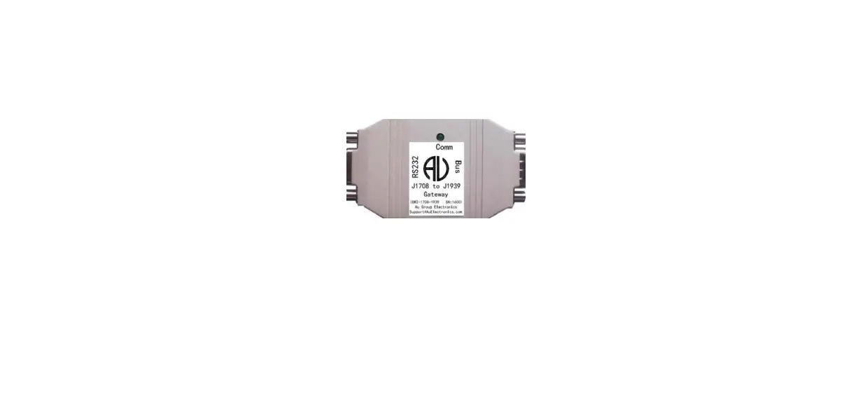
- 1 LED (Bus Communication)
- 1 RS232 interface (DB9 female connector): can be connected to PC or any device with RS232 serial port for device running status monitoring and in-field programming ( default RS232 baud rate: 115.2K).
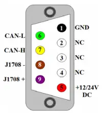
- 1 BUS interface (DB9 male connector): can be connected to J1939/CAN, J1708/J1587 network, and a power supply (+14.2V DC nominal). The pin-out of the DB9 male “BUS” interface is illustrated in Figure 2.
Factory Reprogrammable Default Settings
| MID on J1708 / J1587 network | SA on J1939 network | |
| GW2 device (Off Board Diagnostic Service Tool 1) | 172 | 249 |
| GW2 device shipped after June 9, 2017 | 164 (multiplexer) | 37 (Off Vehicle Gateway) |
MID for Relevant PID (to be received by GW2)
| PID | MID (with priority from high to low) |
| 84 (0X54) – Road Speed | 136, 128, all other MID |
| 245 (0XF5) – Total Vehicle Distance | 128, all other MID |
| 247 (0XF7) – Total Engine Hours | 128, all other MID |
Supported Parameters Cross Reference
| Parameters | SAE J1708 / J1587 | SAE J1939 | |
|
1 | Reference # | PID: 84 | PGN: 65265 SPN: 84 |
| Description | Road Speed | Wheel-Based Vehicle Speed | |
| Transmission rate | 100 ms | 100 ms | |
| Data Range | 0.0 to 205.2 km/h (0.0 to 127.5 mph) | 0 to 250.996 km/h (0.0 to 155.96 mph) | |
| Bit Resolution | 0.805 km/h (0.5 mph) | 1/256 km/h per bit, 0 offset | |
|
2 | Reference # | PID: 245 | PGN: 65248 SPN: 245 |
| Description | Total Vehicle Distance | Total Vehicle Distance | |
| Transmission rate | 10.0 s * | 100 ms | |
| Data Range | 0.0 to 691,207,984.6 km (0.0 to 429496729.5 mil) | 0 to 526,385,151.9 km (327080569.41 mil) | |
| Bit Resolution | 0.161 km (0.1 mi) | 0.125 km/bit, 0 offset | |
|
3 | Reference # | PID: 247 | PGN: 65253 SPN: 247 |
| Description | Total Engine Hours | Engine Hour | |
| Transmission rate | On request * | On request | |
| Data Range | 0.0 to 214,748,364.8 hr | 0 to 210,554,060.75 hr | |
| Bit Resolution | 0.05 h | 0.05 hr/bit, 0 offset | |
|
4 | Reference # | PID: 190 | PGN: 61444 SPN: 190 |
| Description | Engine Speed | Engine Speed | |
| Transmission rate | 100 ms | 20ms | |
| Data Range | 0.0 to 16383.75 rpm | 0 to 8,031.875 rpm | |
| Bit Resolution | 0.25 rpm | 0.125 rpm | |
|
5 | Reference # | PID: 110 | PGN: 65262 SPN: 110 |
| Description | Engine Coolant Temperature | Engine Coolant Temperature | |
| Transmission rate | 1.0 s | 1s | |
| Data Range | 0.0 to 255.0 °F | – 40 to 210 ° C | |
| Bit Resolution | 1.0 °F | 1.0 °C | |
|
6 | Reference # | PID: 100 | PGN: 65263 SPN: 100 |
| Description | Engine Oil Pressure | Engine Oil Pressure | |
| Transmission rate | 1.0 s | 0.5s | |
| Data Range | 0.0 to 879.0 kPa (0.0 to 127.5 lbf/in2) | 0 to 1000 kPa | |
| Bit Resolution | 3.45 kPa (0.5 lbf/in2)) | 4 kPa | |
|
7 | Reference # | PID: 102 | PGN: 65270 SPN: 102 |
| Description | Boost Pressure | Engine Turbocharger Boost Pressure | |
| Transmission rate | 1s | 0.5s | |
| Data Range | 0.0 to 219.8 kPa (0.0 to 31.875 lbf/in2) | 0 to 500 kPa | |
| Bit Resolution | 0.862 kPa (0.125 lbf/in2) | 2 kPa | |
|
8 | Reference # | PID: 86 | PGN: 65265 SPN: 86 |
| Description | Cruise Control Set Speed | Cruise Control Set Speed | |
| Transmission rate | 10s | 100ms | |
| Data Range | 0.0 to 205.2 km/h (0.0 to 127.5 mph) | 0 to 250 km/h | |
| Bit Resolution | 0.805 km/h (0.5 mph) | 1 km/h | |
|
9 | Reference # | PID: 91 | PGN: 61443 SPN: 91 |
| Description | Percent Accelerator Pedal Position | Accelerator Pedal Position 1 | |
| Transmission rate | 0.1s | 100ms | |
| Data Range | 0.0 to 102.0% | 0 to 100 % | |
| Bit Resolution | 0.40% | 0.40% | |
|
10 | Reference # | PID: 92 | PGN: 61443 SPN: 92 |
| Description | Percent Engine Load | Engine Percent Load At Current Speed | |
| Transmission rate | 0.1s | 50ms | |
| Data Range | 0.0 to 127.5% | 0 to 250 % | |
| Bit Resolution | 0.50% | 1% | |
|
11 | Reference # | PID: 105 | PGN: 65270 SPN: 105 |
| Description | Intake Manifold Temperature | Engine Intake Manifold 1 Temperature | |
| Transmission rate | 1s | 0.5s | |
| Data Range | 0.0 to 255.0 °F | – 40 to 210° C | |
| Bit Resolution | 1.0 °F | 1 ° C |
|
12 | Reference # | PID: 108 | PGN: 65269 SPN: 108 |
| Description | Barometric Pressure | Barometric Pressure | |
| Transmission rate | 1s | 1s | |
| Data Range | 0.0 to 109.9 kPa (0.0 to 15.9375 lbf/in2) | 0 to 125 kPa | |
| Bit Resolution | 0.431 kPa (0.0625 lbf/in2) | 0.5 kPa | |
|
13 | Reference # | PID: 168 | PGN: 65271 SPN: 168 |
| Description | Battery Potential(Voltage)) | Battery Potential / Power Input 1 | |
| Transmission rate | 1s | 1s | |
| Data Range | 0.0 to 3276.75 V | 0 to 3212.75 V | |
| Bit Resolution | 0.05 V | 0.05 V | |
|
14 | Reference # | PID: 174 | PGN: 65262 SPN: 174 |
| Description | Fuel Temperature | Engine Fuel Temperature | |
| Transmission rate | 1s | 1s | |
| Data Range | –8192.00 to +8191.75 °F | – 40 to 210 ° C | |
| Bit Resolution | 0.25 °F | 1 ° C | |
|
15 | Reference # | PID: 175 | PGN: 65262 SPN: 175 |
| Description | Engine Oil Temperature | Engine Oil Temperature 1 | |
| Transmission rate | 1s | 1s | |
| Data Range | –8192.00 to +8191.75 °F | – 273 to 1735 deg C | |
| Bit Resolution | 0.25 °F | 0.03125 deg C | |
|
16 | Reference # | PID: 183 | PGN: 65266 SPN: 183 |
| Description | Fuel Rate (Instantaneous) | Engine Fuel Rate | |
| Transmission rate | 0.2s | 100ms | |
| Data Range | 0.0 to 1.07665 L/s (0.0 to 0.28442190 gal/s or 0.0 to 1023.98 gal/h) | 0 to 3,212.75 L/h | |
| Bit Resolution | 16.428 x 10⁻⁶ L/s (4.34 x 10⁻⁶ gal/s or 1/64 gal/h) | 0.05 L/h | |
|
17 | Reference # | PID: 184 | PGN: 65266 SPN: 184 |
| Description | Instantaneous Fuel Economy | Engine Instantaneous Fuel Economy | |
| Transmission rate | 0.2s | 100ms | |
| Data Range | 0.0 to 108.835 km/L (0.0 to 255.996 mpg) | 0 to 125.5 km/L | |
| Bit Resolution | 1.66072 x 10⁻³ km/L (1/256 mpg) | 1/512 km/L per bit, 0 offset | |
|
18 | Reference # | PID: 185 | PGN: 65266 SPN: 185 |
| Description | Average Fuel Economy | Engine Average Fuel Economy | |
| Transmission rate | 10s | 100ms | |
| Data Range | 108.835 km/L (0.0 to 255.996 mpg) | 0 to 125.498046875 km/L | |
| Bit Resolution | 1.66072 x 10⁻³ km/L (1/256 mpg) | 1/512 km/L | |
|
19 | Reference # | PID: 187 | PGN: 65264 SPN: 187 |
| Description | Power Takeoff Set Speed | Power Takeoff Set Speed | |
| Transmission rate | 10s | 100ms | |
| Data Range | 0.0 to 16383.75 rpm | 0 to 8,031.875 rpm | |
| Bit Resolution | 0.25 rpm | 0.125 rpm | |
|
20 | Reference # | PID: 83 | PGN: 61443 SPN: 1437 |
| Description | Road Speed Limit Status | Road Speed Limit Status | |
| Transmission rate | 1s | 50ms | |
| Data Range | 1=active / 0=not active | 00 – Active / 01 – Not Active | |
| Bit Resolution | Binary | 4 states/2 bit, 0 offset |
|
21 | Reference # | PID: 85 | PGN: 65265 SPN: 595 |
| Description | Cruise Control Status | Cruise Control Status | |
| Transmission rate | 0.2s | 100ms | |
| Data Range | 1=active /0=not active | 00 – Cruise control switched off /01 – on | |
| Bit Resolution | Binary | ||
|
22 | Reference # | PID: 89 | PGN: 65264 SPN: 981 |
| Description | Power Takeoff Status | Engine PTO Governor Accelerate Switch | |
| Transmission rate | 1s | 100 ms | |
| Data Range | 1=active / 0=not active | 00 – Off / 01 – On | |
| Bit Resolution | Binary | 4 states/2 bit, 0 offset | |
|
23 | Reference # | PID: 71 | PGN: 65252 SPN: 590 |
| Description | Idle Shutdown Timer Status | Engine Idle Shutdown Timer State | |
| Transmission rate | 1s | 1s | |
| Data Range | 1=active / 0=not active | 00 – Inactive /01 – Active | |
| Bit Resolution | Binary | 4 states/2 bit, 0 offset | |
|
24 | Reference # | PID: 121 | PGN: 61440 SPN: 571 |
| Description | Engine Retarder Status | Retarder Enable – Brake Assist Switch | |
| Transmission rate | 0.2 s | 100 ms | |
| Data Range | 1=on / 0=off | 00 Retarder – brake assist disabled /01 – enabled | |
| Bit Resolution | Binary | 4 states/2 bit, 0 offset |
Per SAE J1708 definition, Total Vehicle Distance (PID: 245) on J1708 network is broadcasted every 10 seconds, however, per SAE J1939 definition, transmission rate for Total Vehicle Distance on J1939 network is 100 milliseconds, so every time after GW2-1708-1939 device is powered up, there will be a period up to 10 seconds the “Total Vehicle Distance ” on J1939 network will displays as 0xFF FF FF FF (255 255 255 255) as there are no “Total Vehicle Distance” data available from J1708 network during at that time frame.
| Timestam p (ms) | P | R | DP | Srr | exid | PF | PS | SA | PGN | DLC | data1 | data2 | data3 | data4 | data5 | data6 | data7 | data8 |
| 70627 | 6 | 0 | 0 | 0 | 1 | 254 | 224 | 37 | 65248 | 8 | 255 | 255 | 255 | 255 | 255 | 255 | 255 | 255 |
| … | 6 | 0 | 0 | 0 | 1 | 254 | 224 | 37 | 65248 | 8 | 255 | 255 | 255 | 255 | 255 | 255 | 255 | 255 |
| 80478 | 6 | 0 | 0 | 0 | 1 | 254 | 224 | 37 | 65248 | 8 | 255 | 255 | 255 | 255 | 21 | 83 | 98 | 0 |
Hardware Connection
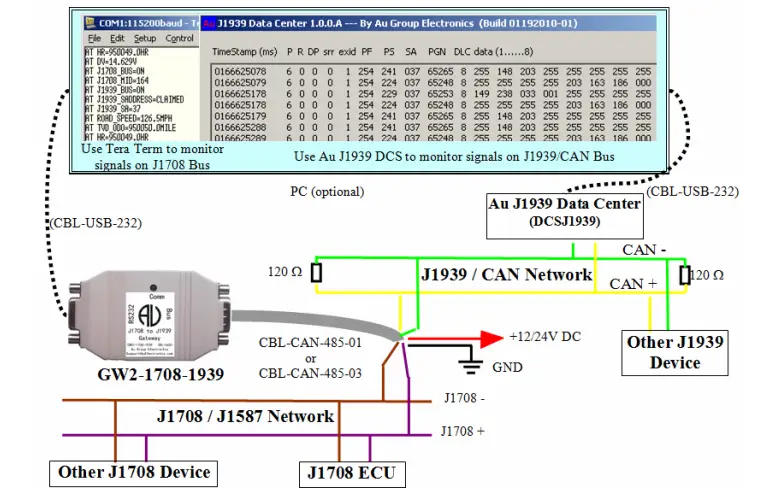
- Following is an example of how GW2 (Au J1708 to J1939 gateway) was used in the lab environment, Au J1939 Data center captured the PGN 65265, 65248, 65253 on J1939 / CAN network, the result is displayed on Au J1939 Data Center PC optional PC was used for demonstration purpose (Figure 3). Two 120-ohm terminal resistor must present on each end of the J1939 network backbone.
- On Figure 3, the J1708 ECU broadcasts “road speed” and “total vehicle distance” signals on J1708 network. Au GW2 receive these two parameters (road speed, odometer signals) on J1708 network . Then it will perform the following:
- convert J1587 “Road Speed” to J1939 “wheel based road speed” and transmit PGN 65265 on J1939 / CAN
- convert J1587 “Total Vehicle Distance” to J1939 “Total Vehicle Distance” and transmit PGN 65248 on J1939 / CAN network.
- In the mean time, it also output ASCII string on RS232, which can be displayed on PC screen using Tera Term (open source serial communication software) for monitoring purpose, please see details at the next paragraph for AT command

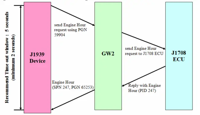
- On Figure 3, A J1939 device (Au J1939 Interpreter) was used to send out Engine Hour request command to J1939 network (using PGN 59904), once GW2 receive the request, it will send the request to J1708 ECU, then J1708 ECU will reply with the current Total Engine Hours and send it over to J1708 network (PID 247). GW2 then convert Total Engine Hour to SAE J1939 Engine Hour and transmit SPN 247 (PGN 65243) on J1939 / CAN network. Engine Hour data flow is illustrated in Figure 4

Optional Accessories
On the Bus side, use CBL-CAN-485-01 or CBL-CAN-485-03 to connect Au J1708 to J1939 Gateway to power supply, J1708 network, and J1939 network: connect black wire to GND, red wire to +12V/24V DC Power Supply , Yellow wire to CAN-L, Green wire to CAN-H), Brown wire to J1708 B -, Violet wire to- J1708 A
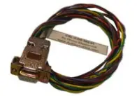 | CBL-CAN-485-01: A 6-wire color coded cable which can be used for Au J1939 devices, Au J1708 devices. One end of the cable is DB9 female connector; it is designed to mate with Au devices on BUS side. The other side of the cable is a pig tail with 3 pairs of twisted color coded wires: Red wire: Power supply, e.g. +12V DC Black wire: Ground Yellow wire: CAN High Green wire: CAN Low Violet: J1708A+ Brown: J1708B- |
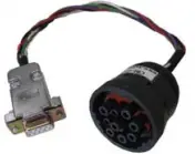 | CBL-CAN-485-03 CBL-CAN-485-03 is a 0.33 meter CAN/J1939/J1708 cable with DB9 female connector and 9-way round threaded plug (HD16-9-1939S). This cable can be used to connect Au J1939 / J1708 products to trucks and school buses equipped with 9 pin diagnostic connectors. |
| AT Command | Description |
| AT J1708_BUS=ON | J1708 Network is ON |
| AT J1708_MID=164 | Device MID is setting at 164 |
| AT J1939_BUS=ON | J1939 Network is ON |
| AT J1939_SADDRESS=CLAIMED | Device Source Address Clamed Status – Claimed |
| AT J1939_SA=37 | Device Source Address is setting at 37 |
| AT ROAD_SPEED=126.5MPH | Road Speed is 126.5 mile per hour |
| AT HR=950049.0HR | Engine Hour is 950049.0 hours |
| AT TVD_ODO=950050.0MILE | Total vehicle distance is 950050.0 mile |
| AT DV=14.239V | Device voltage is 14.239 volts |
AT Command
| AT Command | Description | Command to request information or change default setting |
| AT ID=GW2-1708-1939-001 | Device ID is: GW2-1708-1939-001 | display once at power up, can be requested using: AT ID=?\r\n |
| AT FW=0.1B(32K-BUILD06172017-01) | Device Firmware | display once at power up, can be requested using: AT FW=?\r\n |
| AT SN=1612 | Device Serial Number | display once at power up, can be requested using: AT SN=?\r\n |
| AT DV=14.677V | Device Voltage | Broadcast every 1 second |
| AT J1708_BUS=OFF | J1708 Network Status is off | Broadcast every 1 second |
| AT J1708_MID=164 | Device Message ID – Default setting at 164 (Multiplex) | AT MID=165\r\n (change device default MID to 165) |
| AT J1939_BUS=OFF | J1939 Network Status is off | Broadcast every 1 second |
| AT J1939_SADDRESS=NOTCLAIMED | Device Source Address Clamed Status – not claimed | Broadcast every 1 second |
| AT J1939_SA=37 | Device Source Address is set at 37 | AT SA=249\r\n (change device’s default SA to 249) |


