![]()
LED PLL & DRIVER INSTALLATION GUIDE- WARNING
WARNING – Risk of fire or electric shock. LED Retrofit Kit installation requires knowledge of luminaire electrical systems. Installation should be performed only by a qualified electrician in accordance with the National Electrical Code and relevant local code.
WARNING – Risk of fire or electric shock. Install this kit only in the luminaires that have the construction features and dimensions shown in the photographs and/or drawings.
WARNING – To prevent wiring damage or abrasion, do not expose wiring to edges of sheet metal or other sharp objects.
WARNING – Risk of fire or electric shock. Luminaire wiring and electrical parts may be damaged when drilling for installation of LED retrofit kit. Check for enclosed wiring and components.
Check the Max. case temperature of the fluorescent lamp ballast before replacement. The temperature shall be below or equal to the maximum case temperature (194°F/90°C) of the external driver. The external driver shall be mounted at the same location as the ballast.
- Disconnect power at the source before installation, inspection, or removal. Do not simply switch off the fixture.
- This item is rated at 120-277V. The installer must determine whether line voltage 120-277V is available at the luminaire before installation.
- Not intended for use with emergency exit fixtures or emergency exit lights.
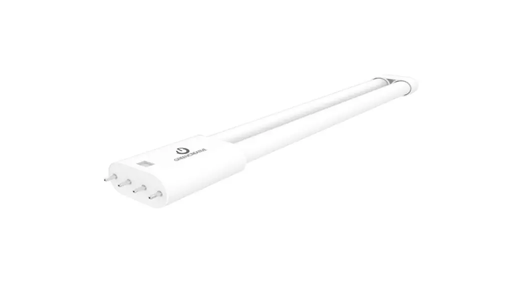
- GREEN CREATIVE PLL EXT lamps and drivers are sold separately. This lamp is DC input. Do not operate LED lamps without a corresponding compatible driver (refer to the compatibility table below).
- Do not use if the product is damaged.
- Do not make or alter any open holes in an enclosure of wiring or electrical components during kit installation.
- “This luminaire has been modified to operate GREEN CREATIVE PLL EXT LED lamps” shall be marked on the retrofit luminaire where readily visible by the user during normal maintenance including re-lamping.
- Risk of fire or electric shock. Do not open or modify. No user-serviceable parts inside.
- Installers should not disconnect existing wires from lamp holder terminals to make new connections at lamp holder terminals. Instead installers should cut existing lamp holder leads away from the lamp holder and make new electrical connections to lamp holder lead wires by employing applicable connectors.
- SUITABLE FOR DAMP LOCATIONS ONLY.
- Complies with Part 15 of FCC. Operation is subject to the following two conditions: (1) This device may not cause harmful interference, and (2) This device must accept any interference received including interference that may cause undesired operation.
- SUITABLE FOR “TYPE IC” OR “TYPE NON-IC” LUMINAIRES.
- No external weight or mechanical force should be applied to PLL or components.
- THE RETROFIT ASSEMBLY IS ACCEPTED AS A COMPONENT OF A LUMINAIRE WHERE THE SUITABILITY OF THE COMBINATION SHALL BE DETERMINED BY UL OR AUTHORITIES HAVING JURISDICTION.
- The minimum lamp compartment dimensions are described below:
| Model Number | 13PLUxxx/EXT | 14PLUxxx/EXT | 19PLUxxx/EXT | |
| Lamp Compartment Dimensions | Length | 24-1/4″ | 24-1/4″ | 24-1/4″ |
| Width | 23-13/16″ | 23-13/16″ | 23-13/16″ | |
| Height | 4-1/8″ | 4-1/8″ | 4-1/8″ | |
| Maximum Lamps in Luminaire | 3 | 3 | 3 | |
| Lampholder-to-Lampholder Spacing | 3-3/8″ | 3-3/8″ | 3-3/8″ | |
Where xxx means 824-965 which indicates CRI and color temperature
| COMPATIBILITY TABLE | |||||
| Model# | 15T8T5HEDRIVER/SD/2CH 15T8T5HEDRIVER/2CH/R | 15T8T5HEDRIVER/SD/4CH 15T8T5HEDRIVER/4CH/R | 24T5HODRIVER/2CH/R | 24T5HODRIVER/4CH/R | |
| Part# | |||||
| 36703 | 13P LU830/EXT | 1 lamp / 2 lamps | 1 lamp / 2 lamps / 3 lamps / 4 lamps | N.A. | N.A. |
| 36704 | 13PLU835/EXT | 1 lamp / 2 lamps | 1 lamp / 2 lamps / 3 lamps / 4 lamps | N.A. | N.A. |
| 13PLL/840/EXT | 1 lamp / 2 lamps | 1 lamp / 2 lamps / 3 lamps / 4 lamps | N.A. | N.A. | |
| 36705 | |||||
| 36706 | 14 P LU830/EXT | 1 lamp / 2 lamps | 1 lamp / 2 lamps / 3 lamps / 4 lamps | N.A. | N.A. |
| 14PLU835/EXT | 1 lamp / 2 lamps | 1 lamp / 2 lamps / 3 lamps / 4 lamps | N.A. | N.A. | |
| 36707 | |||||
| 36708 | 14PLL/840/EXT | 1 lamp / 2 lamps | 1 lamp / 2 lamps / 3 lamps / 4 lamps | N.A. | N.A. |
| 19PLU830/EXT | N.A. | N.A. | 1 lamp / 2 lamps | 1 lamp / 2 lamps / 3 lamps / 4 lamps | |
| 36709 | |||||
| 36710 | 19PLU835/EXT | N.A. | N.A. | 1 lamp / 2 lamps | 1 lamp / 2 lamps / 3 lamps / 4 lamps |
| 36711 | 19PLL/840/EXT | N.A. | N.A. | 1 lamp / 2 lamps | 1 lamp / 2 lamps / 3 lamps / 4 lamps |
| LED PLL & SelectDrive Driver COMPATIBLE GUIDE | ||||
| Part# | Model# | Lamp & Driver lumen output 15T8T5HEDRIVER/SD/2CH 15T8T5HEDRIVER/SD/4CH | ||
| Low (lumens) | Mid (lumens) | High (lumens) | ||
| 36703 | 13PLU830/EXT | 1,200 | 1,450 | 1,800 |
| 36704 | 13PLU835/EXT | 1,200 | 1,450 | 1,800 |
| 36705 | 13PLU840/EXT | 1,300 | 1,600 | 2,000 |
| 36706 | 14PLU830/EXT | 1,300 | 1,600 | 2,000 |
| 36707 | 14PLU835/EXT | 1,300 | 1,600 | 2,000 |
| 36708 | 14PLU840/EXT | 1,450 | 1,750 | 2,200 |
| 36709 | 19PLU830/EXT | 1,700 | 2,100 | 2,600 |
| 36710 | 19PLU835/EXT | 1,700 | 2,100 | 2,600 |
| 36711 | 19PLU840/EXT | 1,850 | 2,250 | 2,800 |
LED PLL INSTALLATION GUIDE – INSTALLATION STEPS
- Read all WARNINGS before continuing this section.
- Make sure POWER IS TURNED OFF at the source to the location at which you are installing the product.
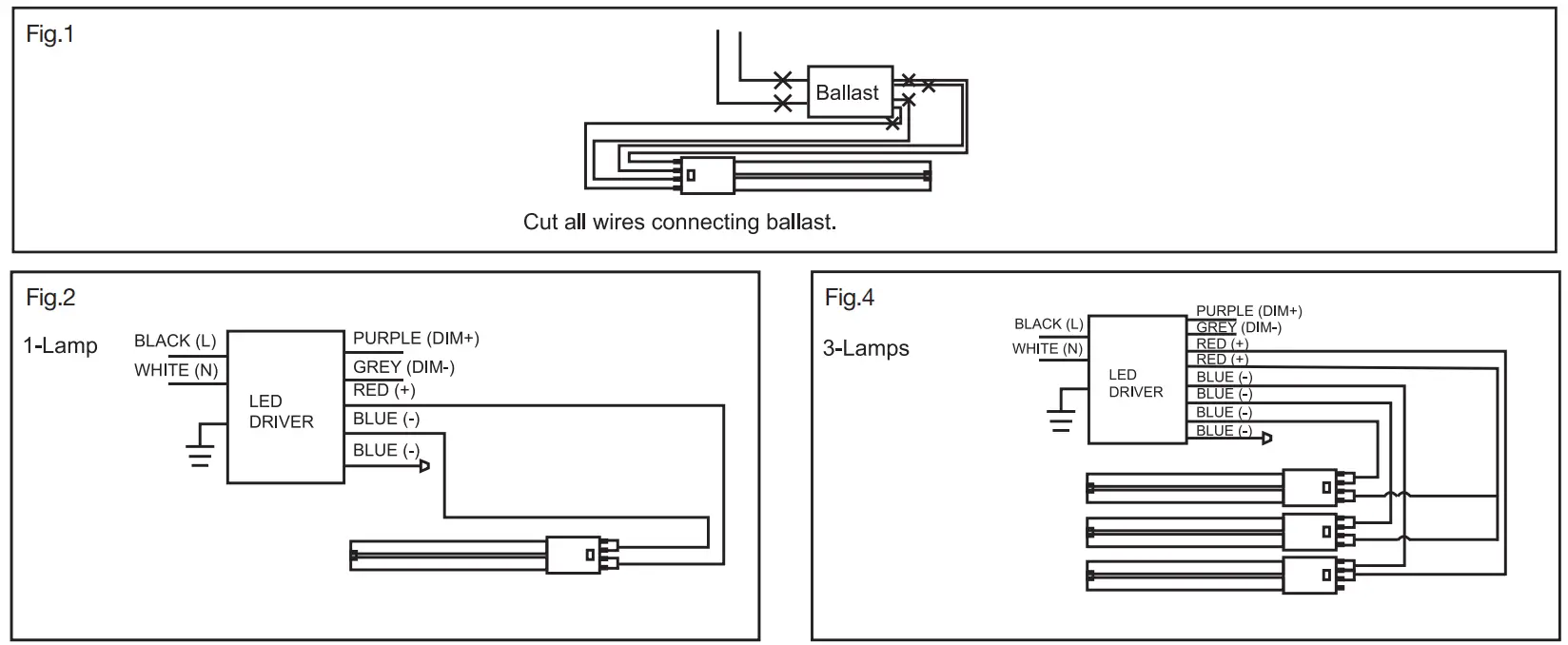
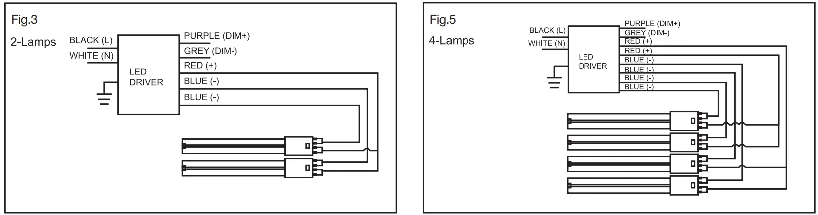
- Remove lens, cover, and fluorescent tubes. Cut away all wires connecting the ballast.
- Make sure to connect the line (L) and neutral (N) to the corresponding ends of the tube marked L and N. Note this product is double-ended, do not wire to a single end.
- Follow wiring diagrams for a number of lamps and original ballast type.
- Visibly affix the “Modification Sticker” to the fixture and reinstall the housing cover and lens if applicable.
- Return power back to the source and installation is complete.
For model #: 13PLL/xxx/EXT, 14PLL/xxx/EXT, 19PLL/xxx/EXT, 15T8T5DRIVER/2CH/R, 15T8T5DRIVER/4CH/R, 15T8T5HEDRIVER/SD/2CH, 15T8T5HEDRIVER/SD/4CH, 24T5HODRIVER/2CH/R, 24T5HODRIVER/4CH/R Where xxx means 824-965 which indicates CRI and color temperature
![]() www.greencreative.com
www.greencreative.com
– [email protected]
– Tel / Fax: (866) 774-5433 –![]() / GREENCREATIVELED
/ GREENCREATIVELED![]() / GClightingLED
/ GClightingLED![]() / GREEN-CREATIVE
/ GREEN-CREATIVE
An ILLUMUS Brand


