BMW 34 11 2 450 161 M Performance Sport Brake Retrofit Kit Instruction Manual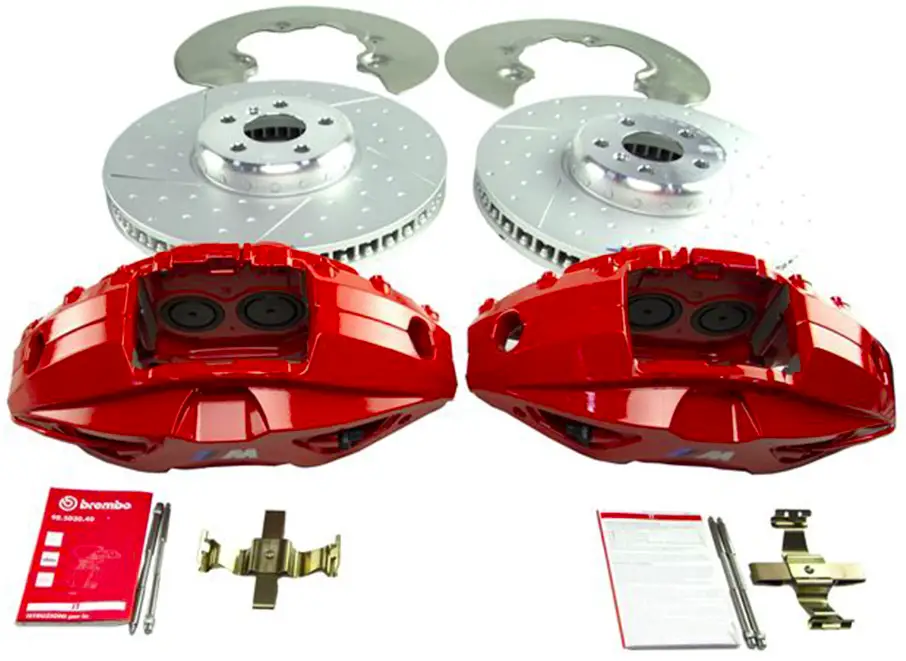
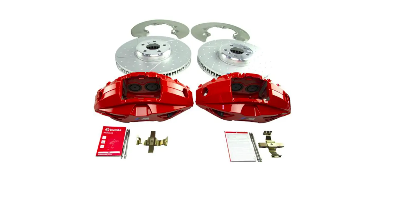
18-Inch M Performance Sport Brake Retrofit Kit.
Front and rear axle with lightweight perforated sport brake disks
BMW 3 Series (G20)
Retrofit kit only suitable for approved wheels (see EPC and also section 7 for details).
Retrofit kit number
34 11 2 450 161: M Performance 18” red sport brake retrofit kit
34 11 2 458 884: M Performance 18” red sport brake retrofit kit including brake booster
Installation time
The installation time is approx. 3.0 hours for retrofit kit number 34 11 2 450 161 and approx. 4.0 hours for retrofit kit number 34 11 2 458 884.
This may vary depending on the condition of the car and its equipment package.
The installation time shown does not include any time spent on programming/coding.
The calculation of the total costs for the programming time must be factored into the calculation of retrofitting costs (must not be invoiced under the warranty).
Important information
Customer information G (Part No. 01 29 2 467 469) must be given to the customer.
These installation instructions are primarily designed for use within the BMW dealership organization and by authorized BMW service companies.
These installation instructions are intended for use by qualified specialist staff trained on BMW cars with the relevant expert knowledge.
All work must be completed using the latest BMW repair manuals, wiring diagrams, servicing manuals and work instructions, in a logical order, using the prescribed tools (special tools), and observing current health and safety regulations.
If you experience installation or function problems, restrict troubleshooting to approx. 0.5 hours for mechanical work and 1.0 hour for electrical work.
To avoid unnecessary extra work and/or costs, send an inquiry straight away to the technical parts support team via the Aftersales Assistance Portal (ASAP).
Quote the following information:
- VIN,
- retrofit kit part number,
- a detailed description of the problem,
- any work already carried out.
Do not archive the hard copy of these installation instructions, since daily updates are supplied in ASAP!
Pictograms
 Denotes instructions that draw your attention to dangers.
 Denotes instructions that draw your attention to special features.
![]() Denotes the end of the instruction or other text
Denotes the end of the instruction or other text
Installation information
All illustrations show LHD (left-hand drive) cars; proceed similarly on RHD (right-hand drive) cars.
Ordering instructions
For the vehicle assignment, see the latest information in the EPC.
Note for the customer (important documents and information for the customer)
The workshop certificate (see appendix) must be completed and given to the customer with customer information G and the TÜV report/parts approval.
The customer must be told that a national acceptance procedure and an amendment of the vehicle’s paperwork are required because the brake system data relevant for the approval have changed. Correct installation must be confirmed by an officially approved expert or inspector.
The design characteristics of the perforated brake disks mean that they may generate noise during use; however this does not affect the stability of the brake system.
Run in the M Performance sport brake carefully for the first 200 km. After this, the full sporty characteristics of the brake system can develop.
Special tools required
34 1 050 Brake piston tool
Front axle parts list
Legend
A Lightweight, perforated front brake disk (2 x, left/right)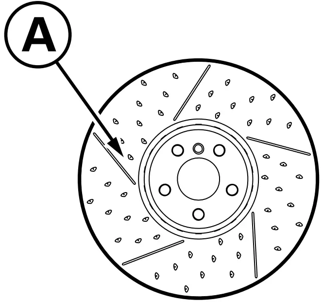
B Hexagon socket screw for brake disk (2 x)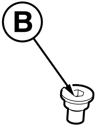
C Front brake calliper (2 x, left/right)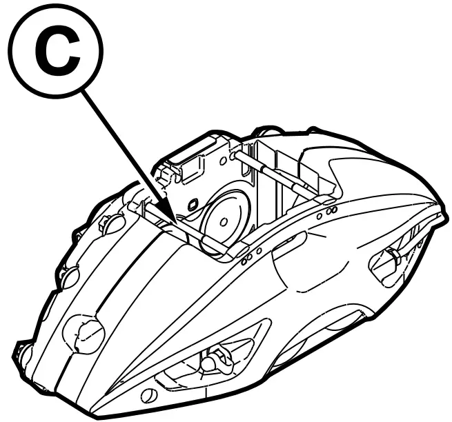
D Torx screw with washer (4 x)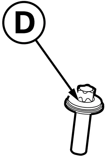
E Front brake pad wear sensor (1 x)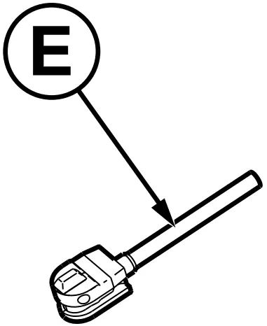
F Front brake pad (1 set)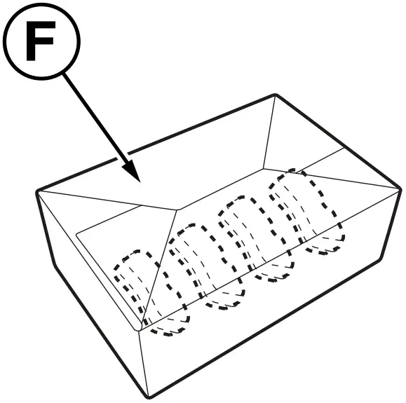
G Customer information (to be given to the customer)
H Front brake guard plate (2 x, left/right)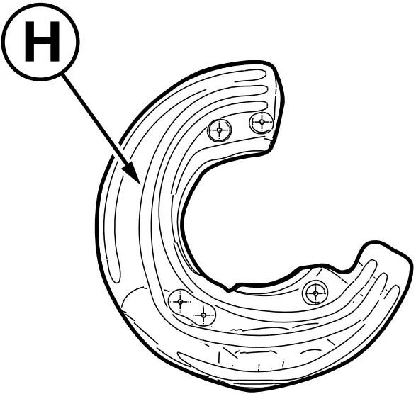
I Hexagon screw for brake guard plate (8 x)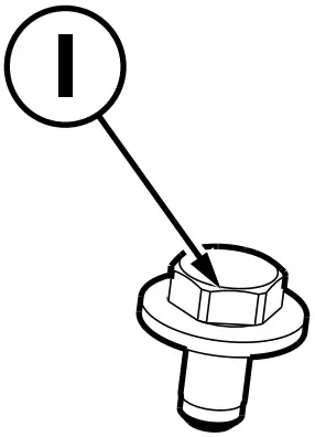
J Brake booster (with Part No. 34 11 2 458 884 only)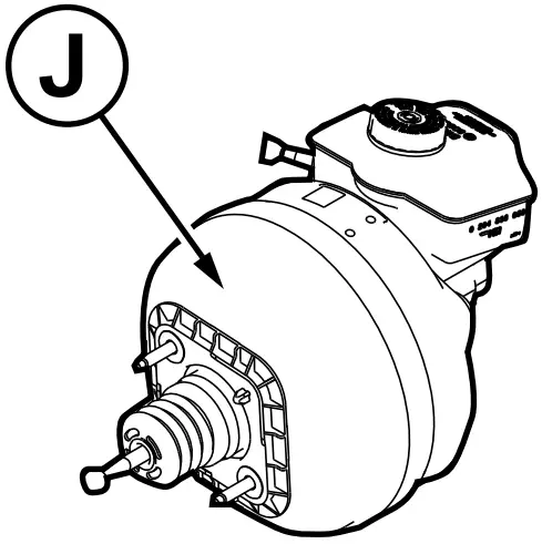
Rear axle parts list
Legend
K Lightweight, perforated rear brake disk (2 x, left/right)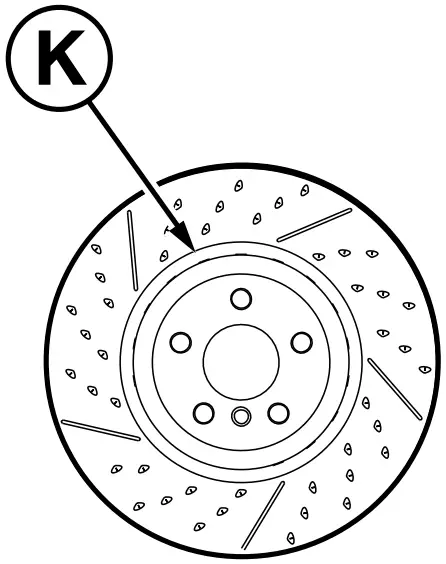
L Hexagon socket screw for brake disk (2 x)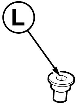
M Rear brake calliper holder (2 x, left/right)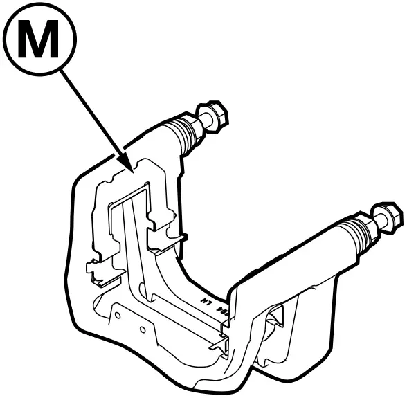
N Rear brake calliper housing (2 x, left/right)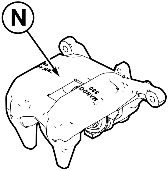
O Hexagon screw for brake calliper (4 x)
P Rear brake pad wear sensor (1 x)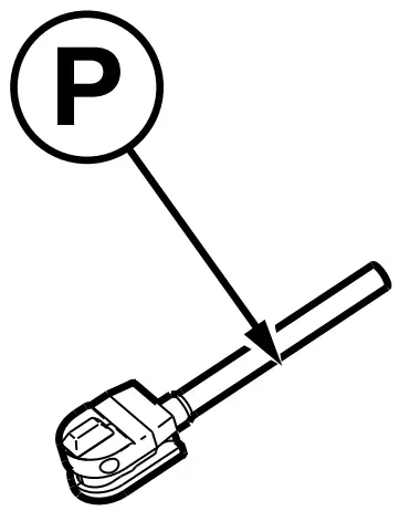
Q Rear brake pad (1 set, including pad guide plates)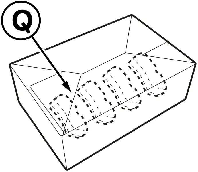
R Rear brake guard plate (2 x, left/right)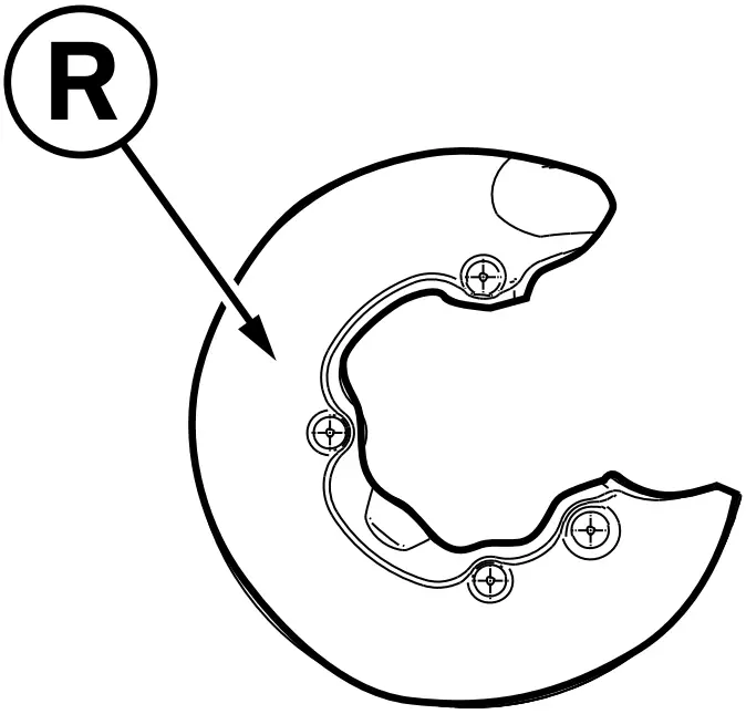
S Hexagon screw for brake guard plate (8 x)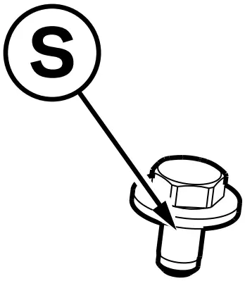
T Cable clip (2 x)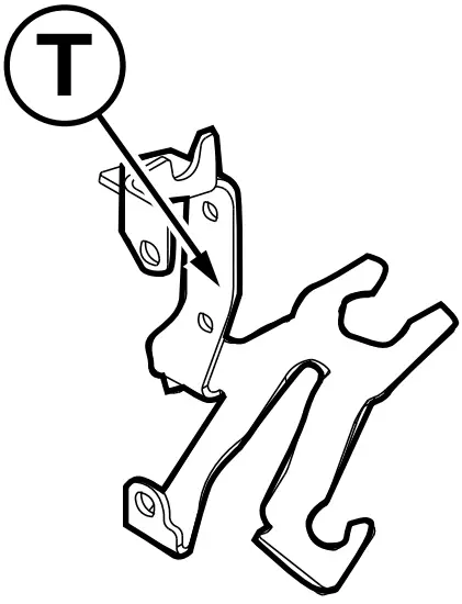
U Design clip (2 x)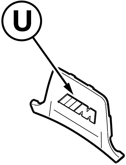
V Actuator (2 x)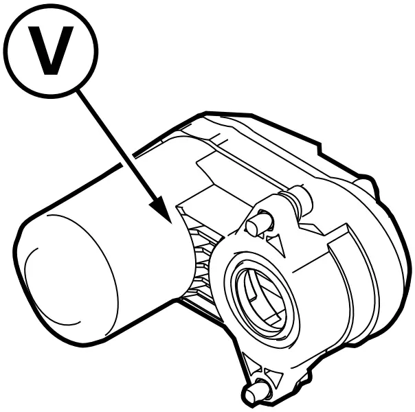
| ISTA/AIR No. | |
| Conduct a brief test | — |
| Disconnect the negative battery cable | 12 00 … |
| The following components must be removed first of all | |
| Front and rear wheel | 36 10 340 |
| Front brake pad wear sensor | 34 35 001 |
| Front brake pad | 34 11 000 |
| Front brake calliper | 34 11 519 |
| Front brake disk | 34 11 220 |
| Front brake guard plates | 34 11 250 |
| Rear brake pad wear sensor | 34 35 003 |
| Rear brake pad | 34 21 200 |
| Rear brake calliper | 34 21 175 |
| Rear brake disk | 34 21 320 |
| Rear brake guard plate | 34 21 284 |
| For 34 11 2 458 884: Remove the brake booster | 34 33 505 |
Front axle installation work
Install the following parts as described in the relevant ISTA/AIR number:
- Install front brake guard plates H using hexagon screws I as described in ISTA/AIR No. 34 11 250
- Install front lightweight brake disks A using hexagram socket screws B as described in ISTA/AIR No. 34 11 220
- Install front brake pads F using brake pad paste as described in ISTA/AIR No. 34 11 000
- Install front brake calliper C using Torx screws D as described in ISTA/AIR No. 34 11 519
- Install front brake pad wear sensor E as described in ISTA/AIR No. 34 35 001
For 34 11 2 458 884: Install brake booster J as described in ISTA/AIR No. 34 33 505
Rear axle installation work
Install the following parts as described in the relevant ISTA/AIR number:
- Install rear brake guard plates R using hexagon screws S as described in ISTA/AIR No. 34 21 284
- Install rear lightweight brake disks K using hexagram socket screws L as described in ISTA/AIR No. 34 21 320
- Install rear brake pads Q using brake pad paste as described in ISTA/AIR No. 34 21 200
Remove the guide pin screws on the rear brake calliper holder M (no longer required as they are already on the brake calliper housing)
Install rear brake calliper N and brake calliper housing M with hexagon screws O as described in ISTA/AIR No. 34 21 745
- Install the design clip U over the brake calliper holder M on the rear brake calliper housing N (see figure below)
- Install rear brake pad wear sensor P as described in ISTA/AIR No. 34 35 003

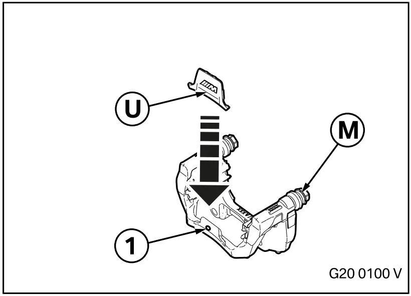
Place the design clip U on the lug and ensure that the spring hooks into the borehole (1) in the rear brake calliper housing M.
Concluding work and coding
The retrofit system requires programming/coding.
- Connect the battery
- Bleed the brake system with DSC as described in ISTA/AIR No. 34 00 046
- Fit the front and rear wheels as described in ISTA/AIR No. 36 10 300
- Encode the retrofit with the Software Service Station (SSS) via the – Retrofit/Sport Brake – path
- Conduct a brief test
- Carry out a function test (please use ISTA/AIR No. 34 00 … General instructions for running-in new
brake disks / brake pads.)
The workshop certificate (see appendix) must be completed and given to the customer with customer information G and the TÜV report/parts approval.
The customer must be told that a national acceptance procedure and an amendment of the vehicle’s paperwork are required because the brake system data relevant for the approval have changed. Correct installation must be confirmed by an officially approved expert or inspector
Important information for the customer: Run in the M Performance sport brake carefully for the first 200 km. After this, the full sporty characteristics of the brake system can develop.
The design characteristics of the perforated brake disks mean that they may generate noise during use; however this does not affect the stability of the brake system. ![]()
Approved wheels
Only Original BMW alloy wheels of 18 inches or over may be used after the 18-inch M Performance sport brake has been installed. This also applies to winter wheels.
The current status of which wheels may be installed is set out in the EPC. ![]()
Workshop certificate
Workshop certificate
M Performance sport brake
Part number
34 11 2 450 161: M Performance 18” red sport brake retrofit kit
34 11 2 458 884: M Performance 18” red sport brake retrofit kit
The M Performance sport brake has been installed on the G20 as described in Installation Instructions No. 01 29 2 467 463.
Extract from the EC type approval, part number 01 29 2 467 465 (available on the ASAP).
Car model: ________________________
VIN: ______________________
Name and address of the vehicle keeper: _____________________________
Place, date
Signature of person responsible
Dealership (company name/stamp)
© BMW AG, Munich 01 29 2 467 463 08/2019 (V/Z) 2.2 11/11


