![]() R1 Mini Series Manufacturer and Supplier
R1 Mini Series Manufacturer and Supplier
User Manual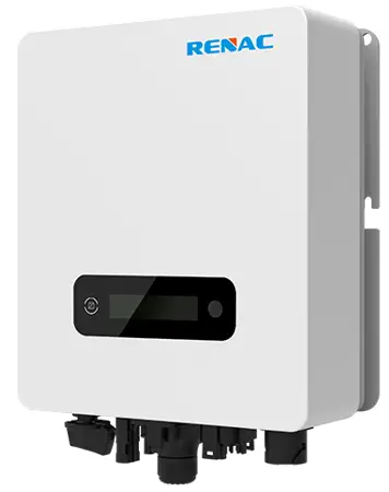 R1 – 1K1 – SS, R1 – 1K6 – SS, R1 – 2K2 – SS ,R1 – 2K7 – SS
R1 – 3K3 – SS, R1 – 3K7 – SS
Introduction
1.1 Introduction
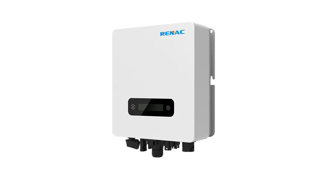
This manual describes solar inverters :R1-1K1-SS/R1-1K6-SS/R1-2K2-SS/R1-2K7-SS/R1-3K3-SS/R1-3K7SS.
These inverters are transformerless based inverter.
Please read the safety instructions in this manual first. Throughout the manual it is assumed that the reader is familiar with AC and DC installations and knows the rules and regulations for electrical equipment and for connecting it to the utility AC grid. It is especially important to be familiar with the general safety rules for working with electrical equipment.
1.2 Applied designations
Throughout the manual important information is shown at different levels depending on the character of the information, as shown here:
| Safety information important for human safety. Violation of warnings may result in injury to persons or death. | |
| Danger of high voltage and electric shock! | |
| Signals danger due to electrical shock and indicates the time (5 minutes) to allow after the inverter has been turned off and disconnected to ensure safety in any installation operation. | |
 | Danger of hot surface! |
 | Product should not be disposed as normal household waste. |
 | CE Mark. |
| ROHS | ROHS Mark. |
| Information important for the protection of property. Violation of this type of information may cause damage and loss of property. | |
| Useful additional information or “Tips and Tricks” on specific subjects. |
1.3 Important safety information![]() Read this before installing, operating or maintaining the inverter.
Read this before installing, operating or maintaining the inverter.
Before installation:
Check for damage to inverter and packaging. If you are in doubt, please contact your supplier before installing the inverter. Check the voltages of the solar modules and make sure they are within the limits of the inverter specifications before connecting them to the inverter.
Installation:
Only trained and authorized personnel familiar with local electrical codes may install the inverter. For optimum safety, please follow the steps described in this manual. Keep in mind that the inverter has two voltage carrying sides, the PV input and the AC grid.
Disconnecting the inverter:
Always disconnect the AC line first! Afterwards disconnect the PV lines. Note that the inverter can still be charged with very high voltages at hazardous levels even when it is disconnected from grid and solar modules. Wait at least 5 min. before proceeding, after having disconnected from grid and PV panels.
Operating the inverter:
Before connecting the AC grid to the inverter, make sure that the installation cover is mounted again. The inverter must not be open during operation.
Maintenance and modification:
Only authorized personnel are allowed to repair or modify the inverter. To ensure optimum safety for user and environment, only the original spare parts available from your supplier should be used.
Functional safety parameters:
Unauthorized changes of functional safety parameters may cause injury or accidents to people or inverter. Additionally it will lead to the cancelling of all inverter operating approval certificates.
1.4 System sizing
![]() When dimensioning a photovoltaic system, it must be ensured that the open circuit voltage of the PV string never exceeds the maximum permissible input voltage, R11K1-SS/R1-1K6-SS/R1-2K2-SS series inverters the maximum input voltage is 500V DC, R1-2K7-SS/R1-3K3-SS/R1-3K7-SS series inverters the maximum input voltage is 550V
When dimensioning a photovoltaic system, it must be ensured that the open circuit voltage of the PV string never exceeds the maximum permissible input voltage, R11K1-SS/R1-1K6-SS/R1-2K2-SS series inverters the maximum input voltage is 500V DC, R1-2K7-SS/R1-3K3-SS/R1-3K7-SS series inverters the maximum input voltage is 550V
DC. Higher voltages may result in permanent damage to the inverter.
The selection of PV string output should be based on the optimum utilization of the invested capital compared to the expected annual energy yield from the system. This optimization depends on local weather conditions and should be considered in each individual case.
The inverter incorporates an input power limiting device, which automatically keeps the power at levels that are safe for the inverter. The limitation depends mainly on internal and ambient temperatures. The limitation is calculated continuously and always allows the maximum possible amount of energy to be produced.
Please use the tool supplied by Renac Power when dimensioning a photovoltaic system.
Technical description of inverters
2.1 Mechanical design
Figure 2-1 shows the outline dimensions of R1-1K1-SS/R1-1K6-SS/R1-2K2-SS/R1-2K7-SS/R1-3K3-SS/R13K7-SS: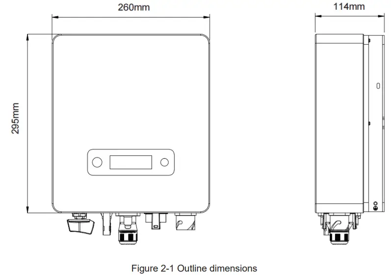
Figure 2-2 shows the electrical terminals of R1-1K1-SS/R1-1K6-SS/R1-2K2-SS/R1-2K7-SS/R1-3K3-SS/R13K7-SS: 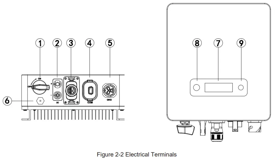
| 1 | DC Switch | 2 | DC (PV Terminal) |
| 3 | I/O Port | 4 | Communication port |
| 5 | AC terminal | 6 | Vent valve |
| 7 | LCD | 8 | LED(Run/Fault) |
| 9 | Key |
![]() For safety reasons, the use of a DC switch is recommended. Between the PV modules and the power modules may be mandatory in some countries.
For safety reasons, the use of a DC switch is recommended. Between the PV modules and the power modules may be mandatory in some countries.
2.2 Electrical system design
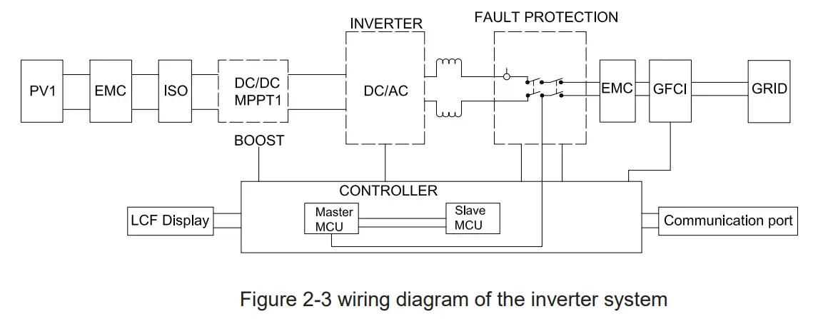
Please refer to chapter 3 for the detail connecting and install methods.
2.3 Technical data
DC Input Data
| Model | R1-1K1-SS………… R1-1K6-SS | R1-2K2-SS | R1-2K7-SS | R1-3K3-SS | R1-3K7-SS |
| Max. Recommended PV Power | 1400W …………………..2400W | 2800W | 3500W 4200W 4800W | ||
| Max.DC Input Voltage | 500V 500V 500V | 550V 550V 550V | |||
| MPPT voltage Range | 50-500V | 50-550V | |||
| Rated Input Voltage | 360V | ||||
| Start-up Voltage | 70V | ||||
| No. of MPP Trackers | 1 | ||||
| No. of Input Strings per Tracker | 1 | ||||
| Max. DC Input Current | 13.5A 13.5A | 13.5A | 13.5A | 16A | 14. |
| Isc | 17A 17A | 17A | 17A | 20A | 17A |
| DC Switch | Optional | ||||
| AC Output Data | ||||||
| Rated AC Power | 1100W | 1600W | 2200W | 2700W | 3300W | 3680W |
| Max.output power | 1100VA | 1600VA | 2200VA | 2700VA | 3300VA | 3680VA |
| Max. AC Current | 4.8A | 7.2A | 9.6A | 12A | 14.4A | 16A |
| Rated AC Voltage/Range | 220V/230V; 160-290V | |||||
| Grid frequency/ range | 50Hz/60Hz ; ±5Hz | |||||
| Adjustable Power Factor[cos φ] | 0.8leading ~0.8lagging | |||||
| Output THDi(@Rated Output) | ≤2% | |||||
| Efficiency | ||||||
| Max.Efficiency | 97.00% | 97.10% | 97.10% | 97.30% | 97.30% | 97.30% |
| Euro Efficiency | 96.50% | 96.60% | 96.60% | 96.80% | 96.80% | 96.80% |
| MPPT Efficiency | 99.90% | 99.90% | 99.90% | 99.90% | 99.90% | 99.90% |
| Protection | ||||||
| DC Insulation Monitoring | Integrated | |||||
| Input Reverse Polarity Protection | Integrated | |||||
| Anti-island Protection | Integrated | |||||
| Residual Current Monitoring | Integrated | |||||
| Over-heat Protection | Integrated | |||||
| AC Overcurrent Protection | Integrated | |||||
| AC Short-circuit Protection | Integrated | |||||
| AC Overvoltage Protection | Integrated | |||||
| DC Surge Protection AC Surge Protection | Integrated(Type III) Integrated(Type III) | |||||
General Data
| Size(Width*Height*Depth) | 295x260x115mm | 335*260*120mm | |||
| Weight | 6.8KG | 6.8KG | 6.8KG | 6.8KG | 7.5KG |
| User Interface | LCD | ||||
| Communication | RS485 or WIFI or GPRS | ||||
| Ambient Temperature Range” | -25 ℃ ~ 60 ℃ | ||||
| Relative Humidity” | 0-100% | ||||
| Operating Altitude” | ≤4000m | ||||
| Standby Self Consumption | <0.2W | ||||
| Topology | Transformerless | ||||
| Cooling | Natural Convection | ||||
| Protection Grades | IP65 | ||||
| Noise | <30dB | ||||
| Warranty | 5 /7/10 years | ||||
Certifications & Standards
| Grid Regulation | VDE 0126-1-1, G98, EN50549, C10/11 PEA, MEA, AS4777 ,CEI0-21,IEC61727,IEC62116,IEC60068,IEC61683 |
| Safety Regulation | IEC 62109-1, IEC 62109-2 |
| EMC | EN 61000-3-2,EN 61000-3-3, EN61000-6-1, EN61000-6-3, IEC61000-4-16,IEC61000-4-18,IEC61000-4-29 |
2.4 Grid codes
| No. | National/Regional Grid Code | Description |
| 9 | C10/11 | Belgium power Grid. |
| 10 | G59 | UK power Grid. |
| 11 | China | China power Grid, meet Grid standards “CN-NBT”. |
| 12 | VDE0126-FR | France power Grid, meet Grid standards “VDE 0126”. |
| 13 | EN50549-PL | Poland power Grid. |
| 14 | BDEW-DE | Germany power Grid, meet Grid standards “BDEW-MV”. |
| 15 | VDE0126-DE | Germany power Grid, meet Grid standards “VDE 0126”. |
| 16 | CEI0-16 | Italy power Grid, meet Grid standards “CEI 0-16”. |
| 17 | G83 | UK power Grid. |
| 18 | Greece Island | Greece Island power Grid. |
| 19 | EN50549-CZ | Czech Republic power Grid, meet Grid standards “EN50438Y2007-CZ”. |
| 20 | IEC61727 | India power Grid. |
| 21 | Korea | Korea power Grid. |
| 22 | EN50549-SW | Sweden power Grid. |
| 23 | China-W | China power Grid, Grid voltage range:160-290V Grid frequency range:47-53HZ. |
| 24 | China-H | China power Grid, meet standards“CQC ”. |
| 25 | IEC61727-IN | India power Grid, meet Grid standards “IEC61727”. |
| 26 | Brazil | Brazil power Grid , meet Grid standards “NBT 16150”. |
| 27 | IEC61727-SL | Sri Lanka power Grid, meet Grid standards “IEC61727”. |
| 28 | Mexico | Mexico power Grid, meet Grid standards “IEC61727 60HZ”. |
| 29 | NZ4777 | New Zealand power Grid, meet Grid standards “NZ4777”. |
| 30 | Philippines | Philippines power Grid, meet Grid standards “IEC61727 60HZ spec”. |
| 31 | IEC61727-SL-W | Sri Lanka power Grid, Grid voltage range:160-290V, Grid frequency range:47-53HZ. |
| 32 | PEA | Thailand power Grid. |
| 33 | PEA-W | Thailand power Grid, Grid voltage range:160-290V, Grid frequency range:47-53HZ. |
| 34 | IEC61627-VN | Vietnam power Grid. |
| 35 | IEC61627-VN-W | Vietnam power Grid, Grid voltage range:160-290V, Grid frequency range:47-53HZ. |
| 36 | MEA | Thailand power Grid. |
| 37 | MEA-W | Thailand power Grid, Grid voltage range:160-290V, Grid frequency range:47-53HZ. |
| 38 | Tunisia | Tunisia power Grid. |
| 39 | Tunisia-W | Tunisia power Grid, Grid voltage range:160-290V, Grid frequency range:47-53HZ. |
Installation and startup
![]() Warning!
Warning!
Before installation and maintenance, AC and DC side doesn’t carry electricity, but if DC side is just disconnected, capacitance still contains electricity, so please wait for at least 5 minutes to ensure the capacitors completely release the energy and inverter is not electrified.![]() Note!
Note!
Inverters must be installed by qualified person.
3.1 Package information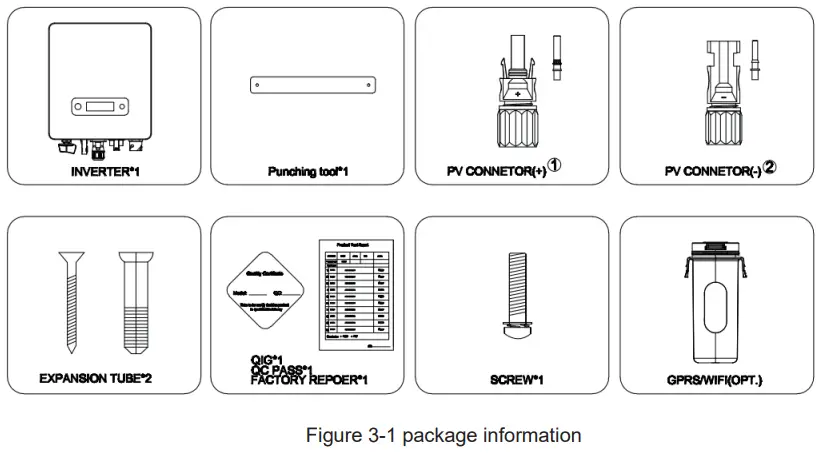
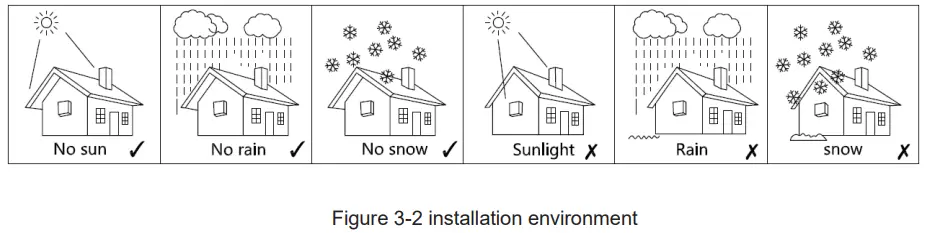
3.2 Installation environment
- In order to achieve optimal performance, the ambient temperature should be kept lower than 45 °C.
- For the convenience of checking the LCD display and possible maintenance activities, please install the inverter at eye level.
- Inverters should NOT be installed near inflammable or explosive items. Any strong electro-magnetic equipment should be kept away from installation site.
- Product label and warning symbol shall be clear to read after installation.
- Please do not install inverter under direct sunlight, rain and snow.

3.3 Installation position
- The installation method and mounting location must be suitable for the inverter’s weight and dimensions.
- Mount on a solid surface.
- Select a well-ventilated place sheltered from direct sun radiation.

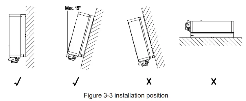
In consideration of heat dissipation and convenient dismantlement, the minimum clearances around the inverter should be no less than the following value 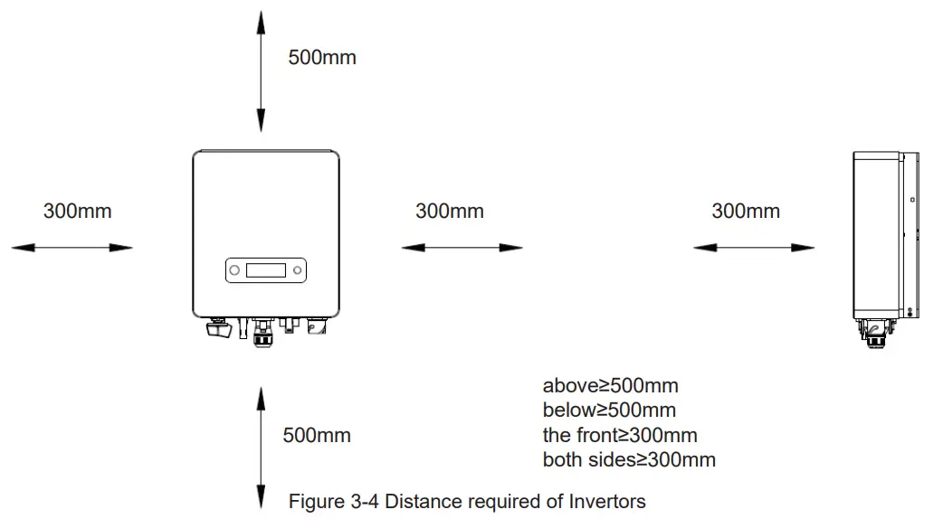
3.4 Mounting procedure
Setp1: Drill 2 Fix Ø11 holes in the wall according to the dimensions.
Step2: Fix the wall mounting bracket on the wall with two expansion bolts in accessory bag.
Setp3: Place the inverter on the wall-mounted bracket and install the fix screw. 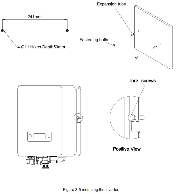
3.5 Electrical connection
3.5.1. Connection to the grid (AC output)
 Add breaker or fuse to AC side, the specification should be more than 1.25 times of rated AC output current.
- The PE line of inverter should be connected to the earth, make sure the impedance of neutral wire and earth wire less than 10 ohm.
- Disconnect the breaker or fuse between the inverter and the utility.
- The integrated leakage current detection device of the inverter can detect external leakage current in real time. When the detected leakage current exceeds the limit value, inverter will quickly disconnect with the grid. If the leakage current protection device is installed externally, the action current should be 300mA or higher.
Connect the inverter to the grid as follows:
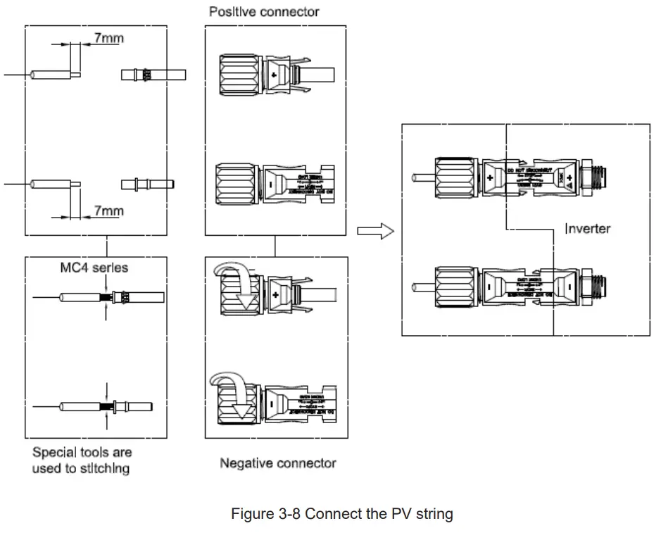
1) Strip off L/N/PE cables as figure 3-6: 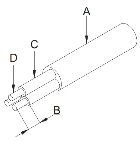
| No. | Description | Remark |
| A | Protective layer | Diameter ranges : 9-16mm |
| B | Length of stripped off | 12mm |
| C | Insulate layer | 50mm |
| D | Cross section of ac cables | 4-6mm² |
Figure 3-6 Strip off PE/N/L cables
2) Tighten the nut clockwise & Tighten L/N/PE cable screws to the terminals according to markings.![]() Fix (Torque: 2~2.5 N.m) the connector of AC cable to the corresponding terminals
Fix (Torque: 2~2.5 N.m) the connector of AC cable to the corresponding terminals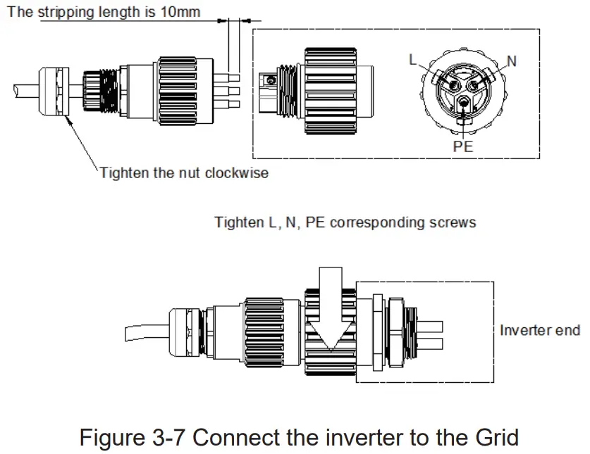
3. Plug Grid side connector into AC connector of inverter end, rotate and tighten clockwise.
3.5.2. Connection to PV string (DC input)
- Before connecting PV string, make sure DC switch is turned off
- Make sure PV string polarity confirms with DC connector, otherwise, it will cause damage to inverter
- Make sure the maximum open circuit voltage (Voc) of each PV string does not exceed the inverter input voltage Vmax under any condition
- Do not connect positive or negative pole of PV string to earth wire. Otherwise, it will cause damage to inverter
3.5.3. Communication
Overview of communication ports: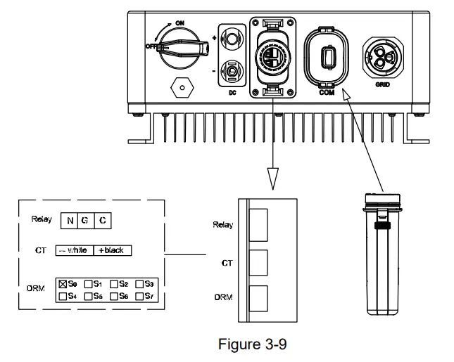
3.5.3.1 WIFI/GPRS Communication (optional)
Connect the WIFI/GPRS module produced by Renac to the COM port of inverter. After successful connection, information such as power generation and running state of the inverter can be viewed via the App on the phone. The details please refer to the module user manual.
The block diagram of the WIFI/GPRS communication system is as follows: 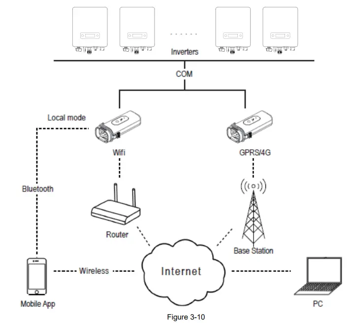
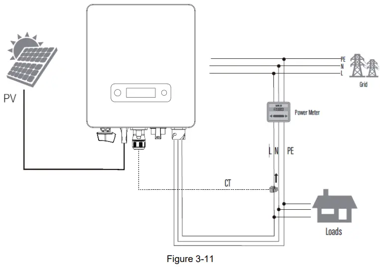
3.5.3.2 CT Connection (Optional)
The inverter is equipped with the feed-in power limit function, and the communication port on inverter is “CT” (figure 3-9), below is the method of connecting the CT in system.
3.5.3.3 DRM connection
The inverter supports the demand response modes as specified in the standard AS/NZS 4777. The inverter has integrated a terminal for connecting to a DRED. The details please refer to figure 3-9, and for CEI standard, DRM S0 is the DI port .
3.5.3.4 Relay connection
The relay can be set to fault alarm output, and user can configure it to be a normal open contact (COM&NO) or a normal close contact (COM&NC).The relay is initially at the NC terminal, and it will trip to another contact when a fault occurs.
Use LED indicators or other equipment to indicate whether the inverter is in the faulty state. The following figures show the typical applications of normal open contact and normal close contact: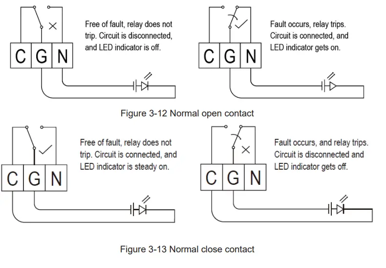
3.6 Starting the inverter
Before turning on the inverter, please confirm:
- Three AC wires (PE/L/N) cable correctly connected to the inverter AC side through AC circuit breaker;
- The DC cable connected correctly to the inverter DC side through DC circuit breaker, please be attention to the cable connected to the two string correctly and it’s polarity;
- The unused terminals are covered.
Starting the inverter:
- Close the DC and AC circuit breaker;
- If the solar panels provide enough energy, the power module will work and the LCD panel will be lit;
- In case you are starting the inverter for the first time, the inverter needs to be commissioned. Commissioning is described on page 17, chapter 4.3.
- Then the inverter will turn into self-check mode and the LCD panel will display the remaining time of connect simultaneously.
- After the inverter turn into normal mode, it feeds electrical energy into grid, and LCD panel will display the generated electrical energy.
As long as the inverter works, it will automatically track the maximum power point to absorb the maximum energy from solar. When night comes, the irradiance is not strong enough to provide energy, the inverter will power off automatically. When the next day comes, the input voltage reaches the start value, it will start again automatically.
User interface
4.1 Led and key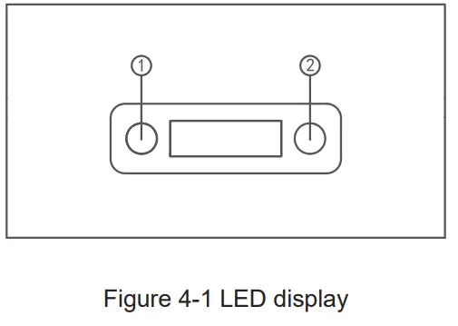
No. | Object | Description |
| 1 | Run (Green LED) | On = Normal operation |
| Flashing = Waiting, checking or starting up | ||
| 1 | Fault (Red LED) | On = Failure |
| Flashing = Temporary failure | ||
| 2 | Pushbutton | Pressing < 1 s: Next |
| Pressing > 2 s: Enter |
4.2 LCD display
Menu structure: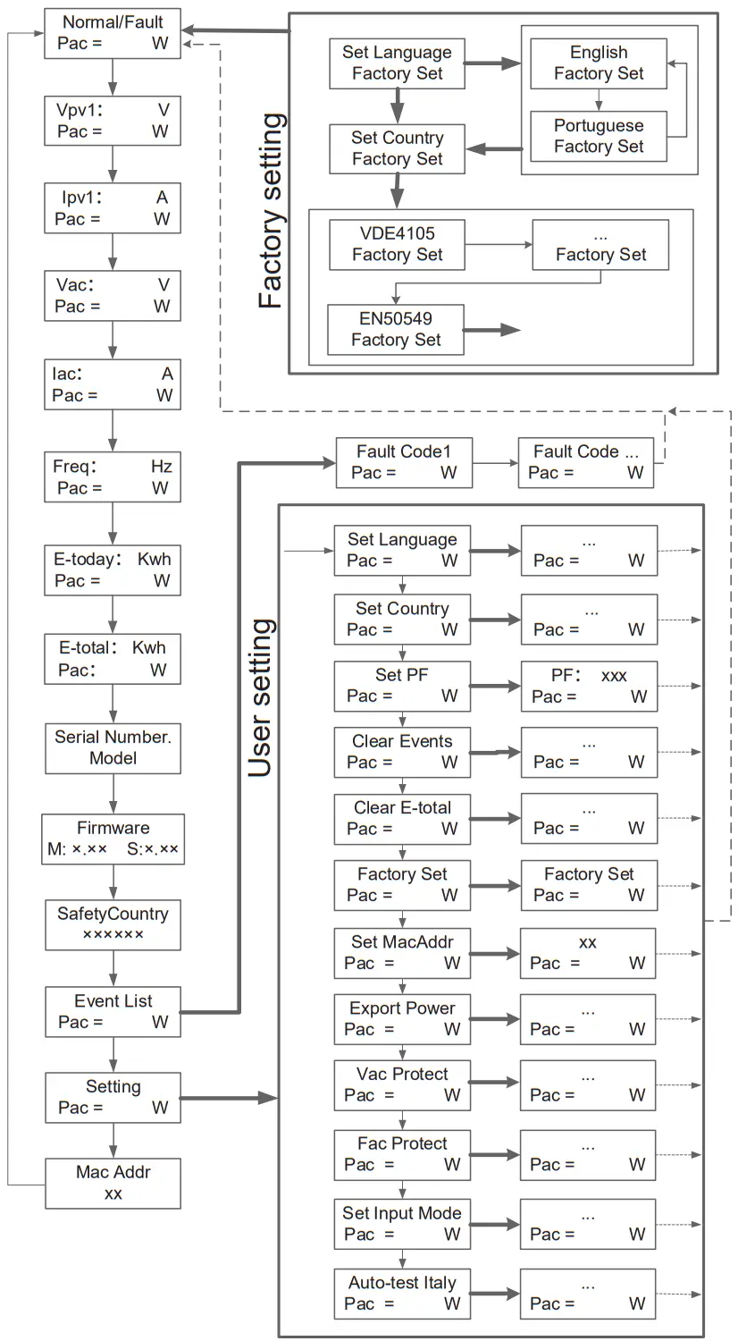 Press the button less than 1 second
Long Press the button
Return
4.3 Factory setting
- Press pushbutton long in order to enter the “Factory setting” menu.
- Press pushbutton long to enter the “language setting” menu.
- Press pushbutton less than 1 sec. to the langue menu you want and Press pushbutton long to select.
- Press pushbutton less than 1 sec. to the country menu you want and Press pushbutton long to select.
4.4 Setting language
- Press pushbutton less than 1 sec. several times until you reach the “Setting” menu.
- Press pushbutton long in order to enter the “setting” menu.
- Press pushbutton less than 1 sec. several times until you reach the “language setting” menu.
- Press pushbutton less than 1 sec. to the langue menu you want and Press pushbutton long to select.
4.5 Setting modbus address
- Press pushbutton less than 1 sec. several times until you reach the “Setting” menu.
- Press pushbutton long in order to enter the “setting” menu.
- Press pushbutton less than 1 sec. several times until you reach the “module add” menu.
- Press pushbutton less than 1 sec. to the modbus address number you want and Press pushbutton long to set.
4.6 Setting export power (CT)
- Press pushbutton less than 1 sec. several times until you reach the “Setting” menu.
- Press pushbutton long in order to enter the “setting” menu.
- Press pushbutton less than 1 sec. several times until you reach the “Export power” menu.
- Press pushbutton long to enter onto “Export power”.
- Set “Export power” as “1”, press pushbutton long to save the value.
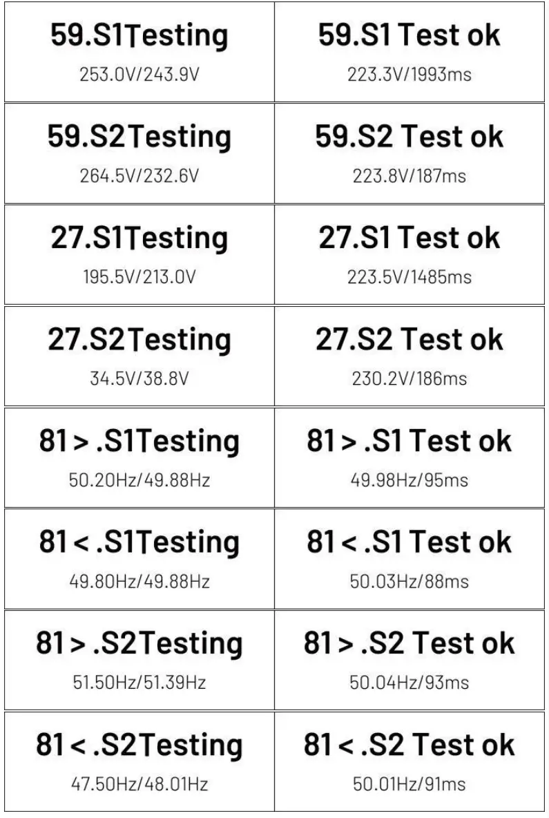
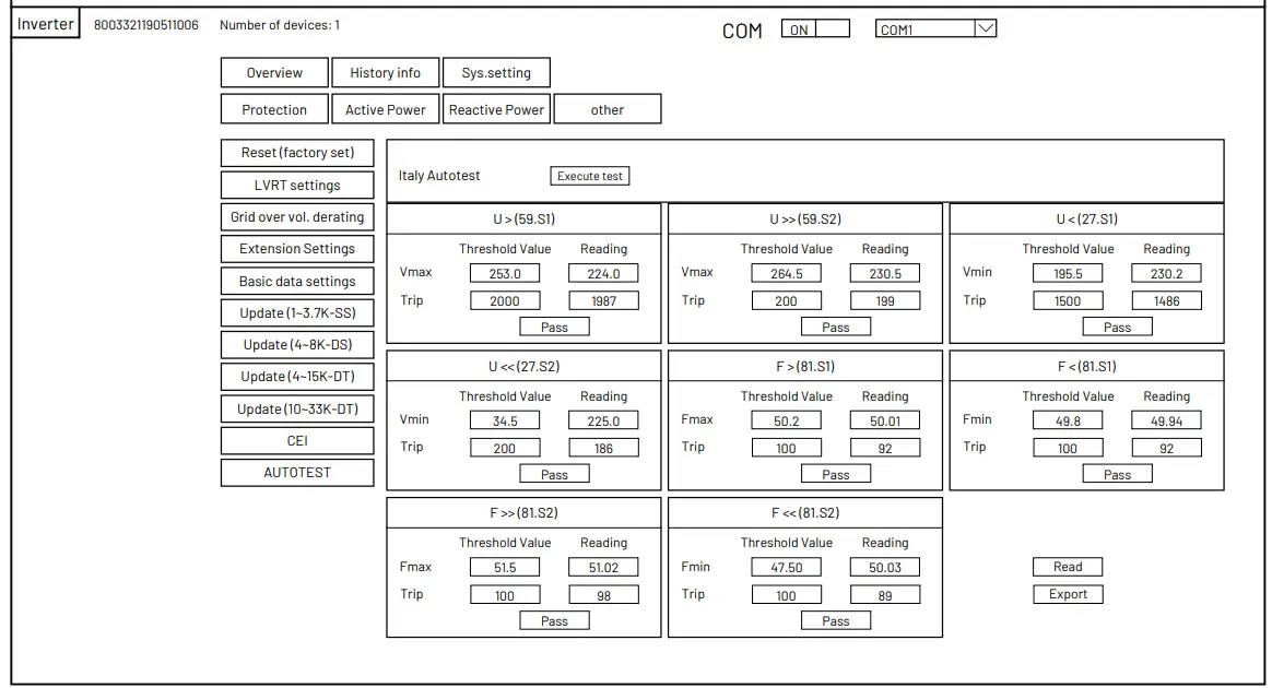
4.7 Self-Test in accordance with CEI 0-21 (Applies to Italy only)
The self-test is only required for inverters, which are commissioned in Italy. The Italian standard requires that all inverters feeding into the utility grid are equipped with a self-test function in accordance with CEI 0-21. During the self-test, the inverter will consecutively check the protection reaction times and values for overvoltage, under voltage, over frequency and underfrequency.
Self-test function is available at any time. It also allows end user get test reports shown on LCD display.
There are two ways to execute the self-test:
Auto-Test from screen:
- Press pushbutton less than 1 sec. several times until you reach the “Setting” menu.
- Press pushbutton long in order to enter the “setting” menu.
- Press pushbutton less than 1 sec. several times until you reach the “AutoTest – Italy” menu (You need to set the inverter country to CEI 0-21 before testing).

- Press pushbutton long to execute the auto -test.
- The inverter will automatically run the test until the screen shows “Test end”, if the test passes, it will show “test ok”, if the test is failed, it will show “test failed”.

Auto-Test from Solar Admin:
- Download and install “Solar Admin” on laptop.
- Connect inverter to laptop via RS485 port.
- When the inverter and “solar admin” are successfully connected. Click “Sys.setting” – “Other” – “AUTOTEST” enter into “Auto – Test” interface.
- Click “Execute” to start the test.
- The inverter will automatically run the test until the screen shows “Test end”.
- Click “Read” to read the test value, and click “Export” to export the test report.
- After click “Read” button, interface will show the test results, if the test passes, it will show “PASS”, if the test is failed, it will show “FAIL”
Warranty
The standard warranty period for the inverter is 60 months from the date of installation and no more than 66 months (5.5 years) from the date of shipment from factory.
5.1 Warranty claim procedure
Please report defective device with a brief error description and SN code to our service mail or service hotline for registration.
Alternatively, please contact your specific dealer or installer if your unit is defective or faulty.
To claim the warranty under the warranty terms of factory, you need to supply us with the following information and documentation regarding the faulty unit:
- Product Model No ( e.g. R1-3K3-SS) and the serial Number (e.g. 8003321190511006).
- Copy of the invoice and warranty certificate for the inverter.
- Error message on LCD screen and additional information regarding the fault/error.
- Detailed information about the entire system (modules, circuits, etc.).
- Documentation of previous claim/exchanges ( if applicable).
In the case of an exchange, the remainder of the warranty entitlement will be transferred to the replacement device. In this event, you will not receive a new certificate, as this replacement will be noted by factory.
5.2 Service after warranty expiration
For products which are out of warranty, factory charges an on-site service fee, parts, labor cost and logistic fee to end-user which can be any/all of:
- On-site attendance fee: Cost of travel and time for the technician in attending on-site;
- Parts: Cost of replacement parts (including any shipping/admin fee that may apply);
- Labor: Labor time fee charged for the technician, who is repairing, maintaining, and installing (hardware or software) and debugging the faulty product;
- Logistic fee: Cost of delivery, tariff and other derived expense when defective products are sent from user to factory or/and repaired products are sent from factory to user.
Appendix A: FAQ (Frequently asked questions)
Sometimes, the PV system does not work normally; we recommend the following solutions for average troubleshooting. This can help the technician to understand the problem and take a proper action.
| Fault | LCD display | Possible actions |
| Clearable Fault | Isolation Fault1 | 1.Check whether the inverter is earthed and test impedance between PV (+) & (-) and the impedance must exceed 3MΩ; 2.Check whether the AC-side has contacts with earth. |
| Grid Faults: 10min OVR Fault OVR Fault UVR Fault OFR Fault UFR | 1.Wait for 5 minutes, if the grid returns to normal, PV inverter automatically restarts. 2.Make sure grid voltage and frequency meet the local specifications. | |
| No utility | 1.Grid is not connected. 2.Check grid connection cables. 3.Check grid usability. 4.If grid is ok and the problem exists still, maybe the fuse in the inverter is open, please call service. | |
| Low Temp Over Temp | 1. The internal temperature of inverter is higher or lower than specified normal value. 2. Find a way to reduce or increase the ambient temperature. 3. if the problem remains, please call local service. | |
| PV1OVFault | 1. Check the open PV DC voltage, and see if it is greater than or too close to 550VDC 2.If PV DC voltage is less than 550VDC, and the problem still occurs, please call local service. | |
| Permanent Fault | Consistent Faults: Consist VGrid Consist Freq Consist GFCI Consist DCI |
1.Disconnect all PV (+) or PV (-) from solar panels |
| RelayFail | ||
| EEPROM R/W Fail | ||
| Sci Comm lose | ||
| Spi Comm lose | ||
| BusHFault | ||
| GFCIDeviceFault | ||
| IGridDevice | ||
| PLLFault | ||
| AutoTestFail | ||
| PV Config fault | ||
| Fan error | ||
| DCI out range | ||
| OCPV1 | ||
| OCIGrid |
![]() SMART ENERGY FOR BETTER LIFE
SMART ENERGY FOR BETTER LIFE
RENAC POWER TECHNOLOGY CO., LTD .
Add: Block 6, No.2, West Jinzhi Road
Suzhou National Hi-Tech District, Suzhou, China
Tel:+86-0512-66677278
[email protected]
www.renacpower.com


