
MEAN WELL DRS-480 All-In-One Intelligent Security Power
Features
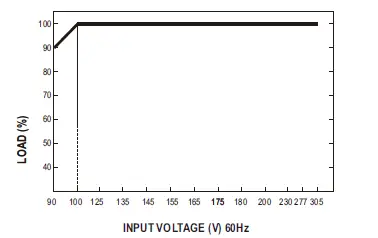
- Universal input 90-305VAC (277VAC available)
- All-in-one function with Power supply, DC-UPS, battery charger and status monitoring in ONE compact unit
- Signal and alarms design meet UL2524,NFPA 1221,BS EN/EN54-4 and GB17945 requirement, with adjustable parameters configurable by communication interface
- Form C relay contacts and LED indicators for AC Fail, Battery Low, Charger Fail, and DC-OK
- Load-dependent high speed battery charging Built-in MODBus protocol, CANBus optional
- Protections: Short circuit/Overload / Over voltage/ Over temperature(auto derating)
- Battery reverse polarity (No damage) / Battery cut off Battery Iow protection / Battery reverse polarity protection
- -30+70’C wide operating temperature
- Cooling by free air convection
- Can be installed on DIN rail TS-35/7.5 or 15
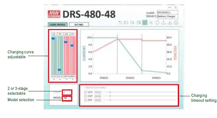
- Charging curve can be set with SBP-001 (Smart programmer sold separately, please refer to: charging current adjustable by VR https://www.meanwell.com/webapp/product/search.aspx?prod=SBP-001)
- 2 or 3-stage selectable by DIP S.W
- Suitable for lead acid and lithium-ion batteries .
- 3 years Warranty
Applications
- Public safety battery back-up (Red box) Security system Emergency lighting system Alarm system Uninterruptible DC-UPS system, battery detection system Central monitoring system Industrial automation
GTIN CODE
- MW Search: https://www.meanwel.com/serviceGTIN.aspx
Description
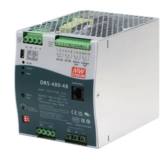
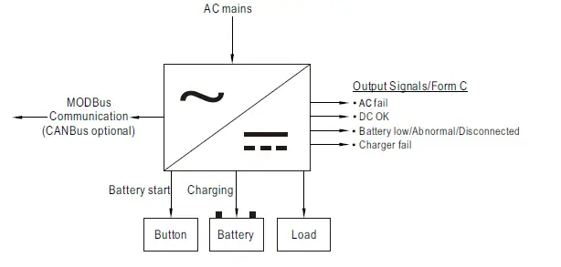
DRS-480 is a 480W AC/DC DIN rail type security power supply series. In addition to the primary output, there is an additional charger circuit that will automatically adjust charge current depending on the primary output current. DRS-480 accepts the universal input between 90VAC and 305VAC, and supports output 24VDC, 36VDC, and 48VDC nominal systems. With high efficiency up to 93.5%, it can operate with free air convection cooling under -30C through 70C ambient temperature. In addition to the key protection features such as overload protection, over voltage protection, battery low voltage disconnect, and battery reverse polarity protection, the DRS-480 also provides Form-C contacts and LED indicator alarm signals for AC-fail, battery low, charger fail, and DC-OK to allow easy integration into security systems that comply with local alarm codes.
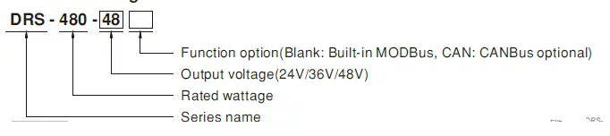
Model Encoding
| OUTPUT | RIPPLE & NOISE (max.) Note.5 | 240mVp-p | 360mVp-p | 480mVp-p | |||||
| VOLTAGE TOLERANCE Note.6 | ±1.0% | ±1.0% | ±1.0% | ||||||
| LINE REGULATION | ±0.5% | ±0.5% | ±0.5% | ||||||
| LOAD REGULATION | ±0.5% | ±0.5% | ±0.5% | ||||||
| SETUP RISETIME Note.7 | 2400ms, 1000ms/230VAC 2400ms, 1000ms/115VAC at full load | ||||||||
| HOLD UP TIME (Typ.) | 16ms/230VAC 10ms/115VAC at full load | ||||||||
|
INPUT | VOLTAGE RANGE | 90 ~ 305VAC 127 ~ 431VDC | |||||||
| FREQUENCY RANGE | 47 ~ 63Hz | ||||||||
| POWER FACTOR (Typ.) | PF>0.95/230VAC PF>0.98/115VAC at full load | ||||||||
| EFFICIENCY (Typ.) | 92.5% | 93.5% | 93.5% | ||||||
| AC CURRENT (Typ.) | 5.4A/115VAC 2.7A/230VAC | ||||||||
| INRUSH CURRENT (Typ.) | COLD START 30A/115VAC 60A/230VAC | ||||||||
|
PROTECTION | SHORT CIRCUIT | Protection type: Constant current limiting, power will shutdown after 5 sec, re-power on to recover. | |||||||
| OVERLOAD | 105 ~ 135% rated output power | ||||||||
| Protection type: Constant current limiting, shutdown output voltage after 5 sec. | |||||||||
| OVER TEMPERATURE | Automatically drop load with temperature only for bat. load. Protection type : Shut down o/p voltage, recover automatically after temperature goes down. | ||||||||
| OVER VOLTAGE | Load main output : 32.4 ~ 37.3V | Load main output : 48.6 ~ 55.9V | Load main output : 64.8 ~ 74.5V | ||||||
| Protection type : Shut down o/p voltage, re-power on to recover | |||||||||
| BATTERY CUT OFF | 20.9±0.5V | 31.3±0.7V | 41.8±1V | ||||||
| REVERSE POLARITY | By internal MOSFET, no damage, recovers automatically after fault condition is removed. | ||||||||
|
FUNCTION |
FORM-C RELAY | AC FAIL | Signals AC failure and activates when input voltage drops below : 79~89VAC of 120AC, 132~187VAC of 220VAC. Relay contact output, ON : AC OK ; OFF : AC Fail ; max. rating : 30Vdc/1A | ||||||
| CHARGER FAIL | Relay contact output, ON : Charger OK ; OFF : Charger Fail ; max. rating : 30Vdc/1A | ||||||||
| DC OK | Signals normal DC output and activates when output voltage > 90% rated value. Relay contact output, ON : DC OK ; OFF : DC Fail ; max. rating : 30Vdc/1A | ||||||||
| BATTERY LOW/ ABNORMAL/ DISCONNECTED | Relay contact output, ON : Battery OK ; OFF : Battery Low ; max. rating : 30Vdc/1A | ||||||||
| Battery low voltage : < 22V±0.3V | Battery low voltage : < 33V±0.4V | Battery low voltage : < 44V±0.5V | |||||||
| BATTERY START | Restart system directly from battery and does not require AC power | ||||||||
| DC-UPS | UPS switch to battery power within 10ms of AC failure | ||||||||
| ADJUSTABLE CHARGING CURRENT | 20% ~ 100% charging current adjustable by VR | ||||||||
| BATTERY TEMPERATURE COMPENSATION | The system can change the battery charging voltage by detecting the temperature (Please refer to page 9~10 for more details). | ||||||||
|
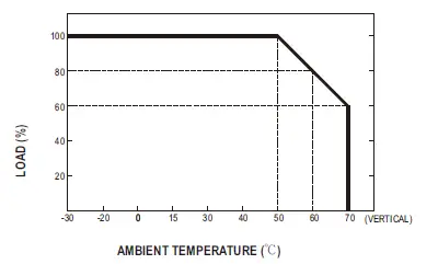
ENVIRONMENT | WORKING TEMP. | -30 ~ +70℃(Refer to “Derating Curve”) | |||||||
| WORKING HUMIDITY | 20 ~ 90% RH non-condensing | ||||||||
| STORAGE TEMP., HUMIDITY | -40 ~ +85℃, 10 ~ 95% RH non-condensing | ||||||||
| TEMP. COEFFICIENT | ±0.03%/℃ (0 ~ 50℃) on Load output | ||||||||
| VIBRATION | 10 ~ 500Hz, 5G 10min./1cycle, 60min. each along X, Y, Z axes | ||||||||
| OPERATING ALTITUDE Note.8 | 2000 meters / OVCⅢ | ||||||||
| OVER VOLTAGE CATEGORY | Ⅲ; According to Dekra BS EN/EN62368-1; altitude up to 2000 meters | ||||||||
|
SAFETY & EMC (Note.10) | SAFETY STANDARDS | UL62368-1, Dekra BS EN/EN62368-1, RCM AS/NZS 62368.1 approved; EAC TP TC 004 pending | |||||||
| WITHSTAND VOLTAGE | I/P-O/P: 4KVAC I/P-FG: 2KVAC O/P-FG: 1.5KVAC | ||||||||
| ISOLATION RESISTANCE | I/P-O/P, I/P-FG, O/P-FG: 100M Ohms/500VDC/25℃/ 70%RH | ||||||||
|
EMC EMISSION | Parameter | Standard | Test Level / Note | ||||||
| Conducted | BS EN/EN55032 (CISPR32) | Class B | |||||||
| Radiated | BS EN/EN55032 (CISPR32) | Class B | |||||||
| Harmonic Current | BS EN/EN61000-3-2 | —– | |||||||
| Voltage Flicker | BS EN/EN61000-3-2 | —– | |||||||
|
EMC IMMUNITY | BS EN/EN55035 , BS EN/EN61204-3, BS EN/EN61000-6-2(BS EN/EN50082-2) | ||||||||
| Parameter | Standard | Test Level / Note | |||||||
| ESD | BS EN/EN61000-4-2 | Level 3, 8KV air ; Level 2, 4KV contact; criteria A | |||||||
| Radiated | BS EN/EN61000-4-3 | Level 3, 10V/m ; criteria A | |||||||
| EFT / Burst | BS EN/EN61000-4-4 | Level 3, 2KV ; criteria A | |||||||
| Surge | BS EN/EN61000-4-5 | Level 3, 1KV/Line-Line ;Level 3, 2KV/Line-Line-Chassis ;criteria A | |||||||
| Conducted | BS EN/EN61000-4-6 | Level 3, 10V ; criteria A | |||||||
| Magnetic Field | BS EN/EN61000-4-8 | Level 4, 30A/m ; criteria A | |||||||
| FIRE DETECTION AND FIRE ALARM SYSTEM | Compliance to BS EN/EN54-4 | ||||||||
| OTHERS | MTBF | 556.6K hrs min. Telcordia SR-332 (Bellcore); 74.5K hrs min. MIL-HDBK-217F (25℃) | |||||||
| DIMENSION | 110*125.2*150.7mm (W*H*D) | ||||||||
| PACKING | 1.65Kg; 6pcs/ 11Kg / 1.42CUFT | ||||||||
| NOTE | https://www.meanwell.com/serviceDisclaimer.aspx | ||||||||
| Arrow | .com. | File Name:DRS-480-SPEC 2022-05-05 | |||||||
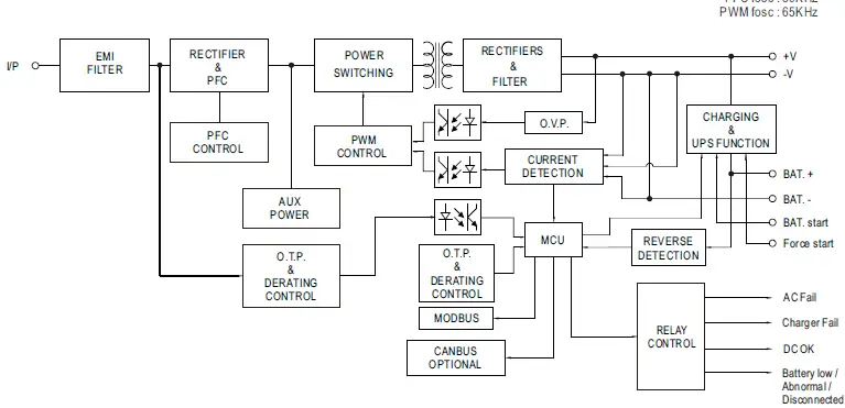
Block Diagram
Derating Curve
Static Characteristics
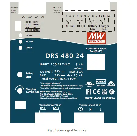
- Alarm signals
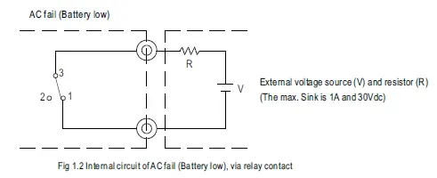
- Alarm Signal is sent out through ” AC fail ” & ” Battery low ” & ” Charger fail “pins via relay contact.
- An external voltage source is required for this function. The maximum applied voltage is 30Vdc and the maximum sink current is 1A. Please refer to Fig 1.2.
- Table1.1 explains the alarm function built in the power supply
INPUT
AC fail DC OK Battery low/Abnormal /Disconnected
Charger fail 2-3 1-3 5-6 4-6 8-9 7-9 11-12 10-12 AC only closed open closed open open closed —– —– AC + BAT. closed open closed open closed open —– —– BAT. only open closed closed open closed open —– —– Low BAT. (<30% capacity)
—– —– —– —– open closed —– —– Charger Fail —– —– —– —– —– —– open closed 

- DC-UPS function
When AC mains drops below:79~89VAC of 120VAC,132~187VAC of 220VAC, UPS function will activate and power source switch battery backup.
- Charger setting
1 OFF: 3 stage(Default), ON: 2 stage 2 Charging curve adjustable:see below 3 
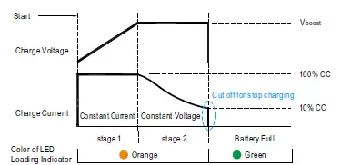
2 or 3-stage selectable by DIP S.W
※ This series provides 2 or 3 stage charging curve.
Charging curve can be adjustable by DIP S.W
State DRS-480-24 DRS-480-36 DRS-480-48 Constant Current 15.4A 10.2A 7.7A Vboost 28.8V 43.2V 57.6V 
State DRS-480-24 DRS-480-36 DRS-480-48 Constant Current 15.4A 10.2A 7.7A Vboost 28.8V 43.2V 57.6V Vfloat 27.6V 41.4V 55.2V
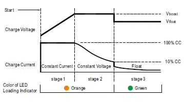
◎ Suitable for lead-acid batteries (flooded, Gel and AGM) and Li-ion batteries (lithium iron and lithium manganese).
※ The default curve is programmable, whereas other pre-defined curves can be activated by the means of the DIP S.W; please refer to the table below and the Mechanical Specification.
Embedded 2 stage charging curve
| DIP SW position | 24V model | |||
| 2 | 3 | Description | CC(default) | Vboost |
| OFF | OFF | Default, programmable | 15.4A | 28.8 |
| ON | OFF | Pre-defined, gel batter | 28.0 | |
| OFF | ON | Pre-defined, flooded battery | 28.4 | |
| ON | ON | Pre-defined, AGM battery,LiFe04 | 29.2 | |
| DIP SW position | 36V model | |||
| 2 | 3 | Description | CC(default) | Vboost |
| OFF | OFF | Default, programmable | 10.2A | 43.2 |
| ON | OFF | Pre-defined, gel battery | 42 | |
| OFF | ON | Pre-defined, flooded battery | 42.6 | |
| ON | ON | Pre-defined, AGM battery,LiFe04 | 43.8 | |
| DIP SW position | 48V model | |||
| 2 | 3 | Description | CC(default) | Vboost |
| OFF | OFF | Default, programmable | 7.7A | 57.6 |
| ON | OFF | Pre-defined, gel battery | 56.0 | |
| OFF | ON | Pre-defined, flooded battery | 56.8 | |
| ON | ON | Pre-defined, AGM battery,LiFe04 | 58.4 | |
Embedded 3 stage charging curve
| DIP SW position | 24V model | ||||
| 2 | 3 | Description | CC(default) | Vboost | Vfloat |
| OFF | OFF | Default, programmable | 15.4A | 28.8 | 27.6 |
| ON | OFF | Pre-defined, gel batter | 28.0 | 27.2 | |
| OFF | ON | Pre-defined, flooded battery | 28.4 | 26.8 | |
| ON | ON | Pre-defined, AGM battery,LiFe04 | 29.2 | 28.0 | |
| DIP SW position | 36V model | ||||
| 2 | 3 | Description | CC(default) | Vboost | Vfloat |
| OFF | OFF | Default, programmable | 10.2A | 43.2 | 41.4 |
| ON | OFF | Pre-defined, gel battery | 42 | 40.8 | |
| OFF | ON | Pre-defined, flooded battery | 42.6 | 40.2 | |
| ON | ON | Pre-defined, AGM battery,LiFe04 | 43.8 | 42.0 | |
| DIP SW position | 48V model | ||||
| 2 | 3 | Description | CC(default) | Vboost | Vfloat |
| OFF | OFF | Default, programmable | 7.7A | 57.6 | 55.2 |
| ON | OFF | Pre-defined, gel battery | 56.0 | 54.4 | |
| OFF | ON | Pre-defined, flooded battery | 56.8 | 53.6 | |
| ON | ON | Pre-defined, AGM battery,LiFe04 | 58.4 | 56.0 | |
SBP-001 can adjust the charging curves (Only CANBus Model)
2 stage charging curve (programable)
| DIP SW position | 24V model | |||
| 2 | 3 | Description | CC(default) | Vboost |
| OFF | OFF | Default, programmable | 15.4A | 28.8 |
| DIP SW position | 36V model | |||
| 2 | 3 | Description | CC(default) | Vboost |
| OFF | OFF | Default, programmable | 10.2A | 43.2 |
| DIP SW position | 48V model | |||
| 2 | 3 | Description | CC(default) | Vboost |
| OFF | OFF | Default, programmable | 7.7A | 57.6 |
3 stage charging curve (programable)
| DIP SW position | 24V model | ||||
| 2 | 3 | Description | CC(default) | Vboost | Vfloat |
| OFF | OFF | Default, programmable | 15.4A | 28.8 | 27.6 |
| DIP SW position | 36V model | ||||
| 2 | 3 | Description | CC(default) | Vboost | Vfloat |
| OFF | OFF | Default, programmable | 10.2A | 43.2 | 41.4 |
| DIP SW position | 48V model | ||||
| 2 | 3 | Description | CC(default) | Vboost | Vfloat |
| OFF | OFF | Default, programmable | 7.7A | 57.6 | 55.2 |
※ SBP-001 is a programmer, particularly for MEAN WELL’s various programmable battery charger models to program the parameters of charging curves, such as the Constant current (CC), tapper current(TC), Constant voltage (CV), float voltage (FV) and so on, to accommodate the diversified battery specification in industry. With the design accounting for simplicity and convenience, users can easily configure MEAN WELL’s programmable battery chargers with SBP-001 programmer and the computer; all of the setups are able to be finished easily by the means of the specific software.
Note:
- Tapper current(TC) default is 10%, can be fine tuned from 2% to 30% by SBP-001 with computer or CANBus Interface.
- Please contact MEAN WELL for more details.
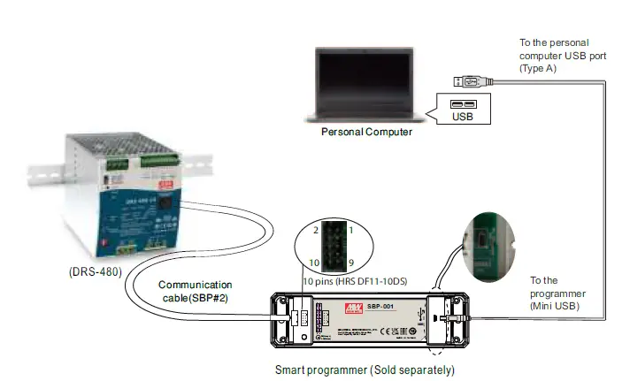
User Interface:
Communication cable for DRS series
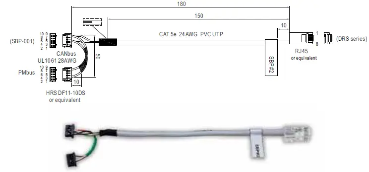
DRS series pin assigment :
| Connector | Pin Assigment | |||||||||
| SBP-001 10pin connector | ||||||||||
(Connector part No.:HRS DF11-10DS) | 1 | 2 | 3 | 4 | 5 (CANH) | 6 (CANL) | 7 | 8 | 9 | 10 (GND) |
DRS-480 RJ45 Communication port | —– | —– | —– | —– | 6 | 7 | —– | —– | —– | 8 |
| Wire color | —– | —– | —– | —– | Green | White/Brown | —– | —– | —– | Brown |
Communication interface
Charging parameters can be modified by MODBus (Built-in) or CANBus(optional) communication commands. For details, please refer to: http://www.meanwell.com/manual.html
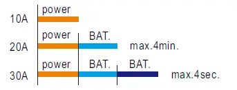
Power Boost Mode
The maximum current on the load output is the 2 times the rated current for 4 minutes max. and 3 times the rated current for 4 seconds max. For example (48V model):
Output load
Battery temperature compensation
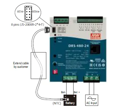
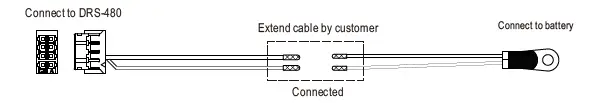
- To exploit the temperature compensation function, please attach the temperature sensor(NTC) which is enclosed with DRS-480, to the battery or the battery’s vicinity.
- DRS-480 is able to work normally without the temperature sensor(NTC).
The compensation parameters included Disable, -3, -4 and -5mV/ ℃ /Cell .It can be modified by communication command of CANBus, MODBus. The factory default value is -3mV/ ℃ /Cell.
It will be regarded as normal temperature and will not be compensated when temperature compensation resistance is not connected; And temperature compensation will only compensate lead-acid battery, not lithium iron battery.
The range of temperature compensation is 0-40℃ , normal temperature 25℃ is the central value, no compensation; When the temperature is < 0 ℃ or > 40 ℃, the current temperature compensation value will be limited to 0 ℃ or 40℃.
24V model as an example
Assuming that V =28.8V, temperature compensation set to -5mV/℃/Cellby communication, TEMP_bat is NTCtemperature detection.
boost
The compensating voltage can be calculated by the following equation:
V =28.8V-5mV*(TEMP_bat -25℃)*12Cell
boost_comp
Max. compensation voltage:
V =28.8V-5mV*(0℃-25℃)*12Cell=30.3V
Min. compensation voltage:
V =28.8V-5mV*(40℃-25℃)*12Cell=27.9V
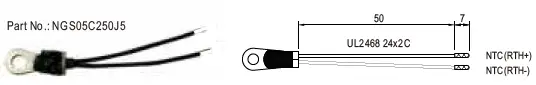
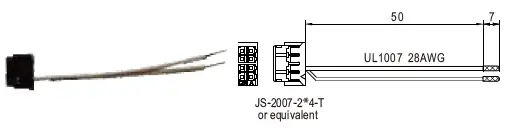
Accessory List
NTC Sensor and mating wire along with DRS-480 (Standard accessory)
| Item | Quantity | |
| 1 | NTC sensor wire
| 1 |
| 2 | Mating wire
or equivalent | 1 |
Connection Diagram
LED alarm
| Function | Description | Output of alarm | |
| DC OK | DC fail | OFF | |
| DC OK | Green | ||
| AC fail | AC fail | Red | |
| AC OK | OFF | ||
|
Status | Charging status | Float | Green |
| Charging: CC/CV | Orange | ||
|
System diagnosis | Discharging | Orange: 1 Blink/Pause | |
| Charger fail | Red : 1 Blink/Pause | ||
| Battery overvoltage / Battery reverse polarity | Red : 2 Blink/Pause | ||
| Battery low / No Battery | Red : 3 Blink/Pause | ||
| Battery discharge peak power timeout. | Red : 4 Blink/Pause | ||
| Over load / short | Red : 5 Blink/Pause | ||
| Over temperature | Red : 6 Blink/Pause | ||
| Timeout | Red : 7 Blink/Pause | ||
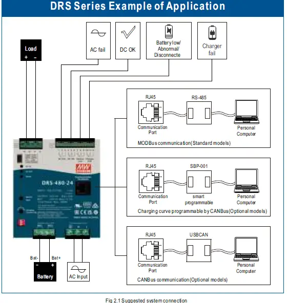
Suggested Application
- Backup connection for AC interruption
- Please refer to Fig2.1 for suggested connection.
The power supply charges the battery and provides energy to the load at the same time when AC mains is OK. The battery starts to supply power to the load when AC mains fails.
- Please refer to Fig2.1 for suggested connection.
- Backup time
Backup time depends on:
※ from the load current
※ from the size of the batteries.
The following table is an example (battery capacity at C10 discharge rate)Battery Load
10AH 20AH 50AH 100AH 200AH 1.5A 350min 13h 33h 67h 133h 3A 125min 350min 17h 33h 67h 5A 60min 180min 600min 20h 40h 7.5A 35min 90min 350min 13h 27h 10A 23min 60min 240min 10h 20h 15A 13min 35min 125min 350min 13h
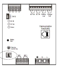
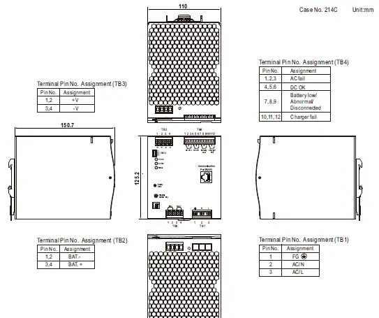
Mechanical Specification
Force button Connector (CN12): JS-2008R-4*2-T or equivalent
| Pin No. | Assignment |
| 1 | 3.3V |
| 2 | GND |
| 3 | RTH+ |
| 4 | RTH- |
| 5 | A0 |
| 6 | A1 |
| 7,8 | Open: Normal Short: Force start |
Terminal Pin No. Assignment (RJ45)
| Pin No. | Function | Description |
| 1,2,3,4,5 | NC | Retain for future use. |
| 6 | Data+ | For MODBus model:Serial Date used in the MODBus interface. |
| CANH | For CANBus model:Date line used in the CANBus interface. | |
| 7 | Data- | For MODBus model:Serial Clock used in the MODBus interface. |
| CANL | For CANBus model:Date line used in the CANBus interface. | |
| 8 | GND-AUX | Auxillary voltage output GND. The signal return is isolated from the output terminals(+V & -V). |
Installation Instruction
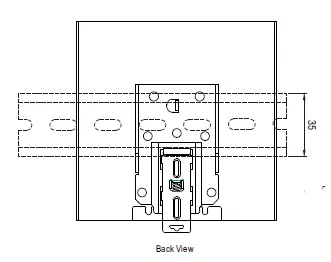
This series fits DIN rail TS35/7.5 or TS35/15.
For installation details, please refer to the Instruction manual.
ADMISSIBLE DIN rail:TS35/7.5 OR TS35/15
(For reference only. Not included with unit.)
Installation Manual
Please refer to : http://www.meanwell.com/manual.html


