AMERICAN LIGHTING CTRL-DMXB-RGBW-4Z Intelligent Touch Panel
Product Introduction
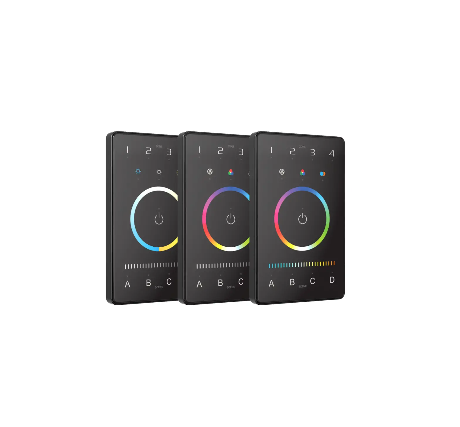
The lntelligentTouch Panel is an American base wall switch, integrating Bluetooth 5.0 SIG Mesh protocol and OMX signals. It is a simple but elegant design with CNC aviation aluminum frame and 2.50 tempered glass. The panel is suitable for multi-scene and multi zone lighting control applications. Working with Bluetooth systems makes it more convenient and intelligent.
Technical Specs
| Model | UB 2 | UB4 | UB5 |
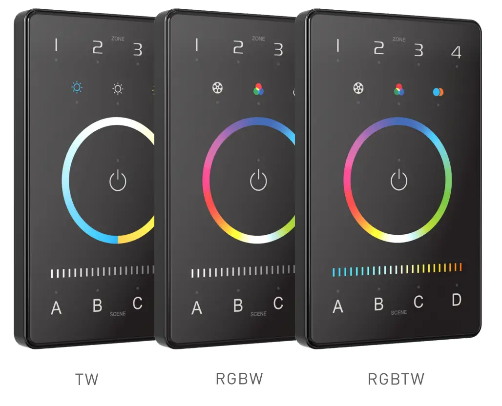
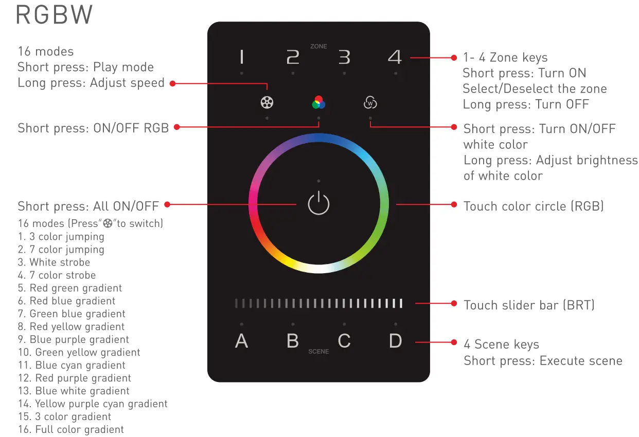
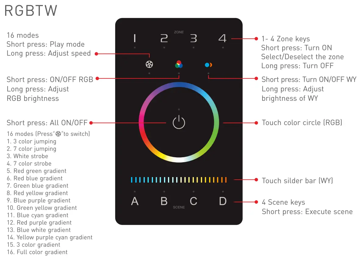
| Control mode | TW | RGBW | RGB TW |
| Input voltage | 12-24VDC, Powered by Class 2 | ||
| Wireless proto col type | Bluetooth 5.0 SIG Mesh | ||
| Output signals | OMX 512 | ||
| Zones | 4 | ||
| Working temperature | -20°C-55°C | ||
| Dimens ions[LxWx H] | 120x75x301mm) | ||
| Package sizel LxWxH) | 158×1 13x621mm) | ||
| Weight (G.W.) | 225g | ||
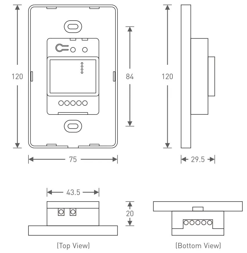
Product Size
Unit: mm
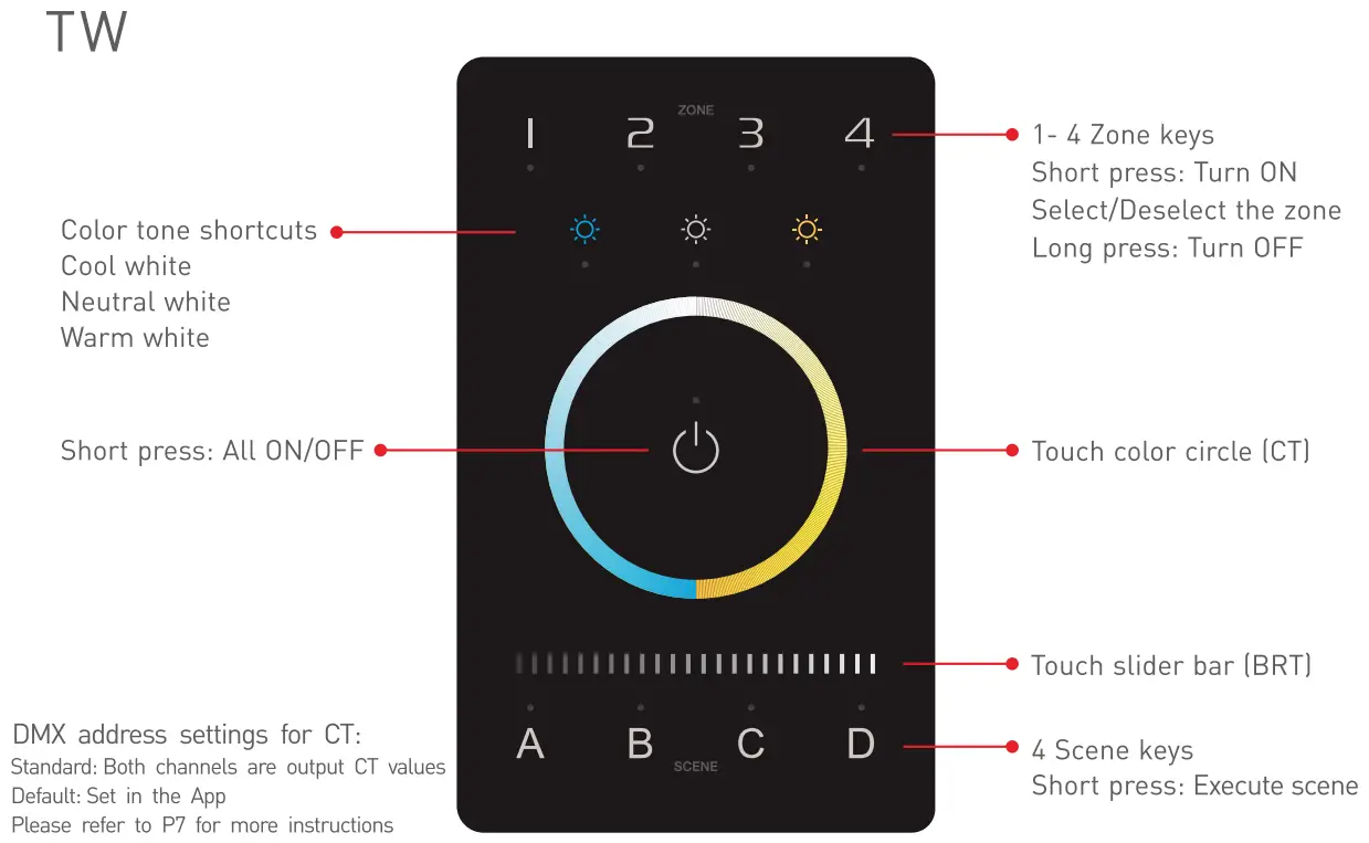
Key Functions
DMX Application Diagram
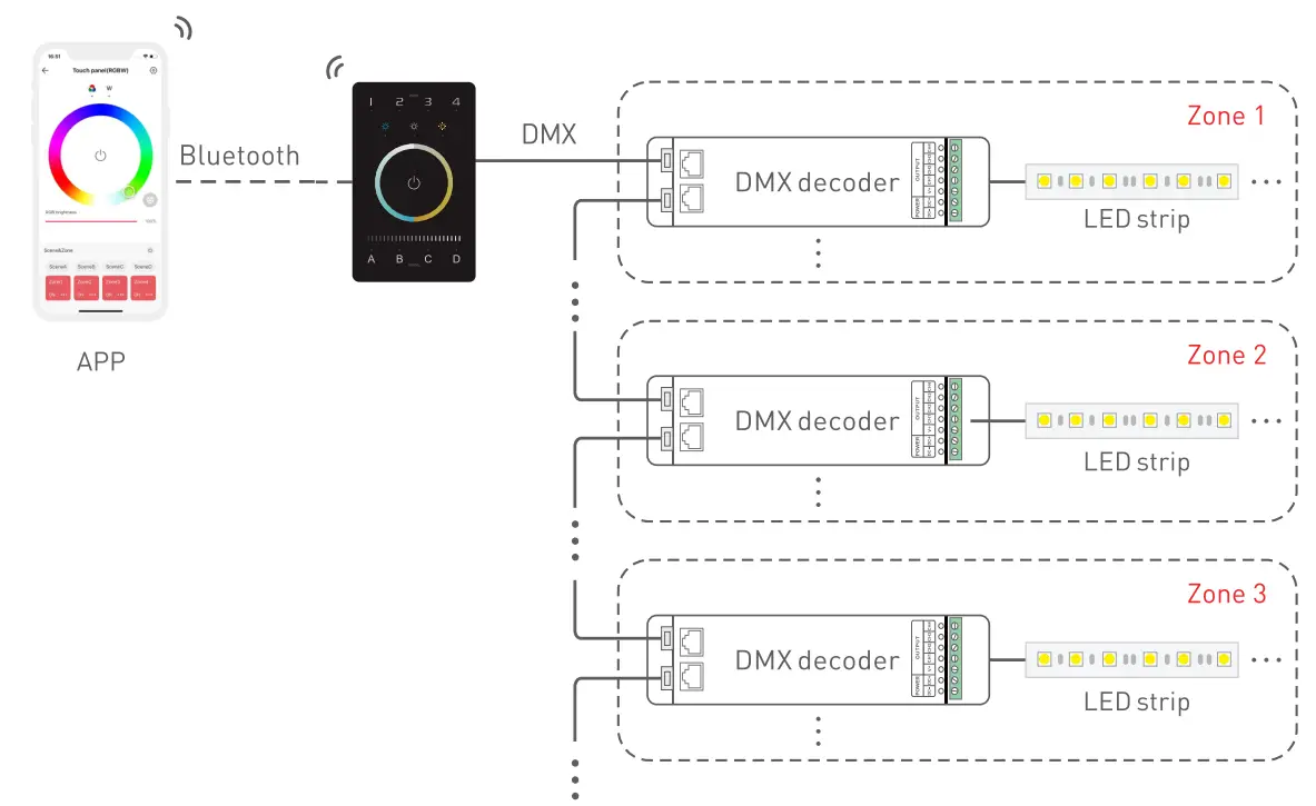
Each zone can be installed with multiple decoders. When the total number of decoders in 4 zones exceeds 32, please add DMX signal amplifiers.
Warning
Changes or modifications to this unit not expressly approved by the party responsible for compliance could void the user’s authority to operate the equipment.
This device complies with Part 15 of the FCC Rules.
Operation is subject to the following two conditions:
[1] This device may not cause harmful interference, and [2] this device must accept any interference received, including interference that may cause undesired operation.
Note: This equipment has been tested and found to comply with the limits for a Class B digital device, pursuant to part 15 of the FCC Rules.These limits are designed to provide reasonable protection against harmful interference in a residential installation. This equipment generates.uses and can radiate radio frequency energy and, if not installed and used in accordance with the instructions, may cause harmful interferenceto rad io communications. However, there is no guarantee that interference will not occur in a particular installation. If this equipment does cause harmful interference to radio or television reception, which can be determined by turning the equipment oft and on, the user is encouraged to try to correct the interference by one or more of the following measures:
- Reorient or relocate the receiving antenna.
- Increase the separation between the equipment and receiver.
- Connect the equipment into an outlet on a circuit different from that to which the receiver is connected.
- Consult the dealer or an experienced radio/TV technician for help.
To maintain compliance with FCC’s RF exposure guidelines, the distance must be at least 20cm between the radiator and your body, and fully supported by the operating and installation configurations of the transmitter and its antenna[s].
* This manual is subject to changes without further notice. Product functions depend on the goods. Please feel free to contact our official distributors if you have any question.
ODX Channel Output Sheet
Types/Zone/Addresses | DIM | CT | CT2 | RG8W | RG8WY |
1 | DIM1 | Cl | 8RT1 | R1 | R1 |
| 2 | DIM2 | Wl | CT1 | G1 | G1 |
3 | DIM3 | C2 | 8RT2 | 81 | 81 |
| 4 | DIM4 | W2 | CT2 | W1 | W1 |
5 | DIM1 | C3 | 8RT3 | R2 | Y1 |
| 6 | DIM2 | W3 | CT3 | G2 | R2 |
7 | DIM3 | C4 | 8RT4 | 82 | G2 |
| 8 | DIM4 | W4 | CT4 | W2 | 82 |
9 | DIM1 | Cl | 8RT1 | R3 | W2 |
| 10 | DIM2 | Wl | CT1 | G3 | Y2 |
11 | DIM3 | C2 | 8RT2 | 83 | R3 |
| 12 | DIM4 | W2 | CT2 | W3 | G3 |
13 | DIM1 | C3 | 8RT3 | R4 | 83 |
| 14 | DIM2 | W3 | CT3 | G4 | W3 |
15 | DIM3 | C4 | 8RT4 | 84 | Y3 |
| 16 | DIM4 | W4 | CT4 | W4 | R4 |
17 | DIM1 | Cl | 8RT1 | R1 | G4 |
| 18 | DIM2 | Wl | CT1 | G1 | 84 |
19 | DIM3 | C2 | 8RT2 | 81 | W4 |
| 20 | DIM4 | W2 | CT2 | Wl | Y4 |
: | : | : | : | : | : |
500 | DIM4 | W2 | CT2 | W1 | Y4 |
: | : | : | : | : | / |
| 512 | DIM4 | W4 | CT4 | W4 | / |
* As shown in the sheet above, every 4 DIM addresses are circulated in 4 zones, every 8 addresses of CT1 and CT2 are circulated in 4 zones, every 16 RGBW addresses are circulated in 4 zones, every 20 RGBWY addresses are circulated in 4 zones.
Installation Instructions
Step 1: Remove the panel plate with a flathead screwdriver, as shown below.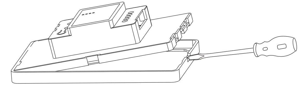
Step 2: Attach the wires to the panel, as shown in the diagram below. Please be sure to turn off the power to the circuit at the circuit breaker or fuse box before attaching the wires.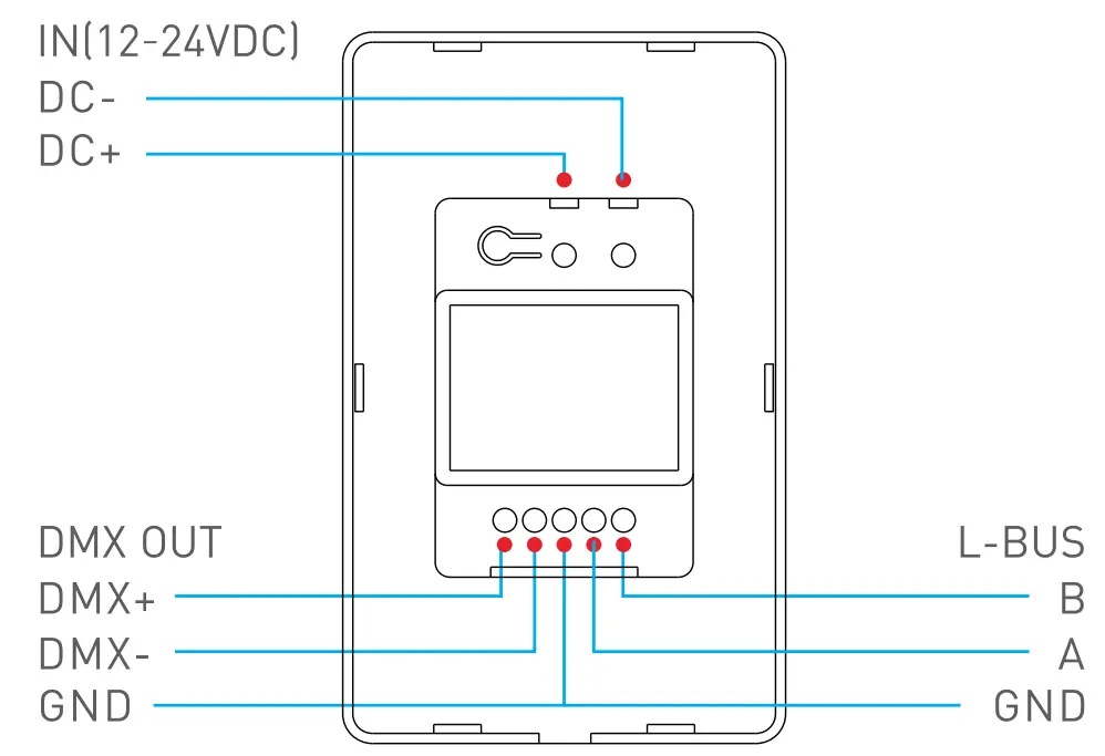
Step 3: Install the panel plate. Once the wires are attached correctly, you can gently fold any excess wire and compress the panel into the junction box. Tighten the screws to secure the panel plate to the box.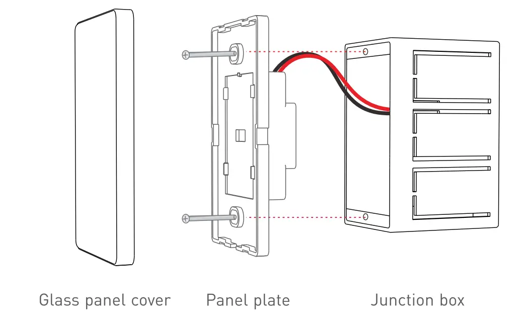
Step 4: Put the panel cover in place. Gently snap the panel cover onto the plate.
Attentions
- Please use in spacious and open space. Avoid metal obstructions above and in front of products.
- Please use in a coo land dry environment.
- No disassembly of products so as not to affect the warranty.
- Avoid direct contact with light and heat.
- Please do not open, modify, repair or maintain products without authorization, otherwise warranties are not allowed.