HiTEC DLVR-L05D Airspeed Sensor
Introduction
Thank you for purchasing the Hitec Commercial Solutions Airspeed Sensor, featuring the best-in-class DLVR pressure sensor. All Sensors’ CoBeam2 technology improves both sensitivity and long-term stability, allowing the Hitec Airspeed Sensor to provide accurate and reliable performance for professional use. Plus, its flexible interfaces and open-source firmware enable seamless compatibility with unmanned systems and other demanding applications.
Specifications
Variants
The Hitec Airspeed Sensor is offered in four configurations, each with a different operating pressure range.
| Pressure Sensor | Sensing Range (in. H20) | Speed Range (at STP and AMSL) |
| DLVR-L05D | +/- 5 | ~ 80kts (41m/s) |
| DLVR-L10D | +/- 10 | ~ 120kts (62m/s) |
| DLVR-L20D | +/- 20 | ~ 170kts (87m/s) |
| DLVR-L60D | +/- 60 | ~ 280kts (144m/s) |
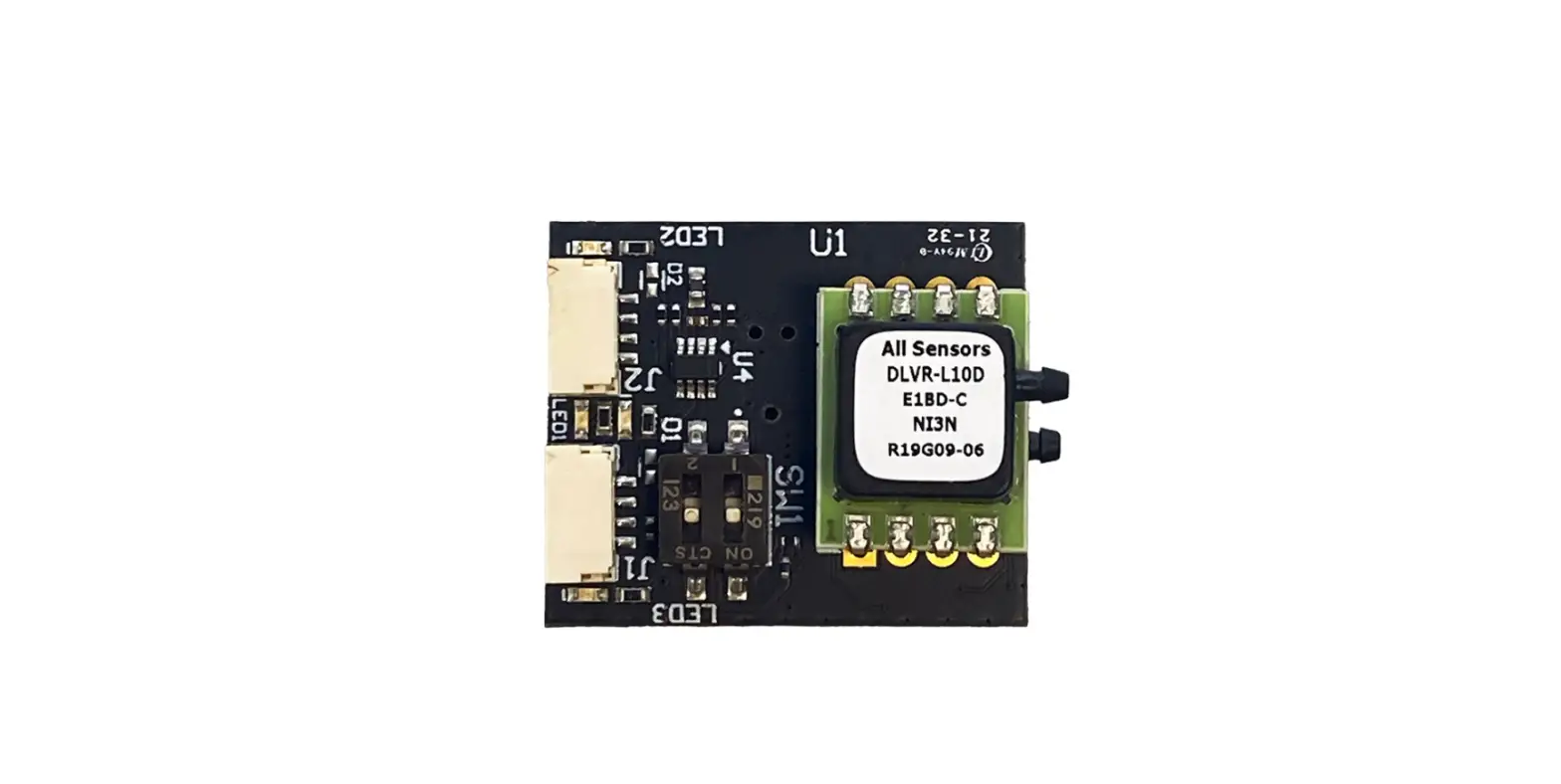
Hardware & Sensors
| Pressure Sensor | DLVR-LxxD-E1BD-I-PI3N |
| MCU | STM32G441 |
| Firmware | AP_Periph |
| Interfaces | I2C, CAN |
Physical
| Dimensions | 30 x 25 mm (1.18 x 0.98 in) |
| Weight | 6 g (0.2 oz) |
Performance
| Input Voltage Range | 5 to 36VDC |
| Operating Temperature Range | -20C to 85C |
| Humidity Range | 0 to 95% RH |
| Proof Pressure | 200 in. H20 (75KPa) |
| Burst Pressure | 300 in. H20 (125KPa) 800 in. H20 (200KPa) for DLVR-L60D |
Connectivity
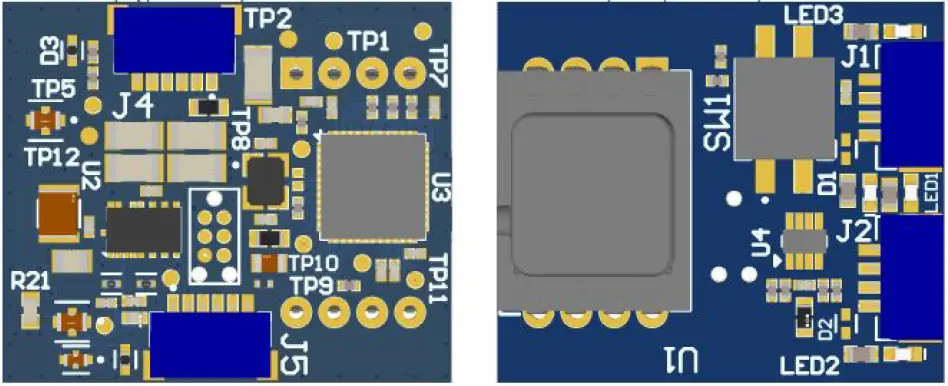
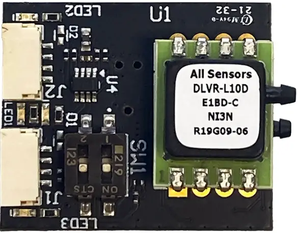
Components & Functions
| J1 | JST-GH 4-pin | DroneCAN connection to AP_Periph |
| J2 | JST-GH 4-pin | I2C connection to pressure sensor |
| J4 | JST-SH 6-pin | Debug connector for MCU |
| J5 | JST-SH 6-pin | UART and GPIO/ADC node connector |
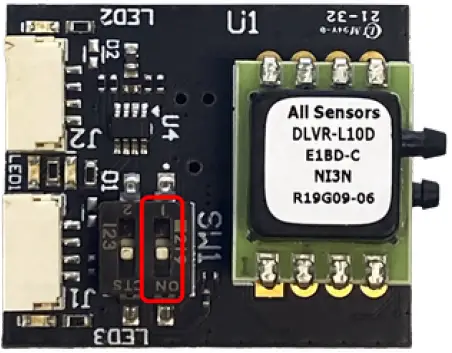
| SW1 | 2-Position DIP Switch | Toggle connection mode & CAN termination |
LED Indicators
| Mode/State | LED1
Bootloader | LED2
I2C Status | LED3
CAN Status | LED4
Power |
| Power Applied
No Firmware | Off | Off | Off | On |
| Bootloader Mode | Blinking quickly | Off | Off | On |
| CAN Mode
DNA Server Found | Off | Off | Blinking at 1Hz | On |
| CAN Mode
Awaiting DNA | Off | Off | Triple blink pattern | On |
| I2C Mode | Off | Blinking at 1Hz | Off | On |
| No Power | Off | Off | Off | Off |
Pinouts
| J1 | Pin 1 | VIN (5-36VDC) |
| Pin 2 | CAN H | |
| Pin 3 | CAN L | |
| Pin 4 | GND |
| J2 | Pin 1 | VIN (5-36VDC) |
| Pin 2 | I2C SCL | |
| Pin 3 | I2C SDA | |
| Pin 4 | GND |
| J4 | Pin 1 | STM32_VDD |
| Pin 2 | UART3 TX | |
| Pin 3 | UART4 RX | |
| Pin 4 | SWDIO | |
| Pin 5 | SWCLK | |
| Pin 6 | GND |
| J5 | Pin 1 | +3V3 |
| Pin 2 | UART1 TX | |
| Pin 3 | UART1 RX | |
| Pin 4 | GPIO1 / ADC1_6 | |
| Pin 5 | GPIO2 / ADC1_7 | |
| Pin 6 | GND |
Pitot Tube
The Airspeed Sensor should be connected to the pitot tube using 1/16” flexible tubing. Ensure that the tubing is secure on the barbs of the DLVR pressure sensor. Tube order does not matter when configured appropriately in Ardupilot.
Ardupilot Integration Guide
I2C
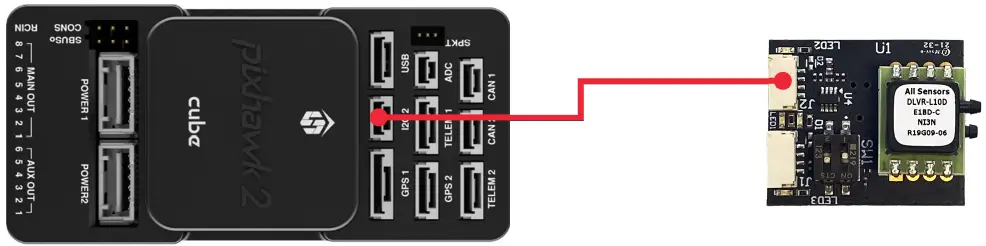
Connecting to the Airspeed Sensor using the I2C connector uses a direct I2C connection for the DLVR pressure sensor. The MCU still boots but is disconnected from the I2C bus.
- Move position 2 of the DIP switch to the OFF position, towards the J2 connector. This places the Airspeed Sensor in I2C mode.

- Connect the J2 connector of the Airspeed Sensor to the autopilot’s I2C connector using the provided JST-GH cable. Or make your own wiring harness using the pinouts detailed previously.

- Configure the following parameters to enable the Airspeed Sensor and select the appropriate DLVR sensor driver. Note that some parameters may vary by flight controller hardware – consult autopilot manufacturer documentation as required. Reboot the autopilot for the changes to take effect.
Sensor DLVR-L05D DLVR-L10D DLVR-L20D DLVR-L60D ARSPD_TYPE 7 9 10 12 ARSPD_BUS 0 ARSPD_TUBE_ORDER 2 ARSPD_USE 1
DroneCAN
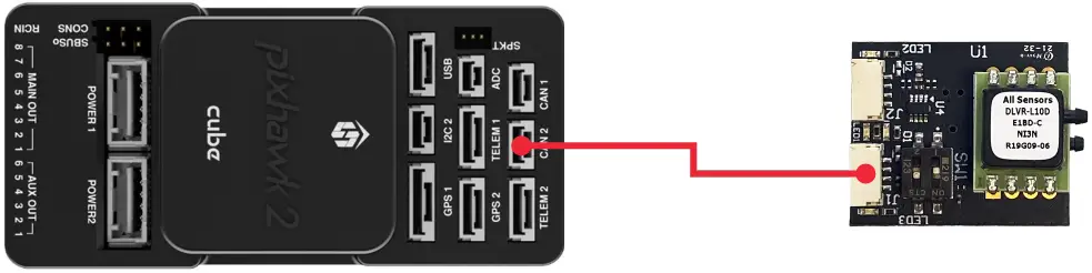
Connecting to the Airspeed Sensor using the CAN connector uses the AP_Periph firmware on the MCU to manage DroneCAN communications with the DLVR sensor. It also provides a DroneCAN node for external peripherals connected to the board’s UART and GPIO signals in the J4 expansion connector.
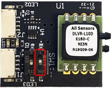
- Move position 2 of the DIP switch to the ON position, towards the J1 connector. This places the Airspeed Sensor in CAN mode.

- If bus termination is desired, move position 1 of the DIP switch to the ON position. This connects an on-board 120-ohm termination resistor between the CAN signal lines.

- Connect the J1 connector of the Airspeed Sensor to the autopilot’s CAN connector using the provided JST-GH cable. Or make your own wiring harness using the pinouts detailed previously.

- Configure the following parameters to enable the Airspeed Sensor and DroneCAN communications in general. In this case, the correct DLVR sensor driver for your board’s pressure range is preconfigured within the MCU. Note that some parameters may vary by flight controller hardware – consult autopilot manufacturer documentation as required.

| ARSPD_TUBE_ORDER | 2 |
| ARSPD_USE | 1 |
| ARSPD_TYPE | 8 |
| CAN_D1_PROTOCOL | 1 |
| CAN_P1_BITRATE | 1000000 |
| CAN_P1_DRIVER | 1 |
Firmware Update
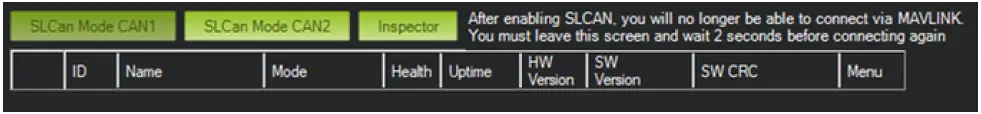
The AP_Periph firmware on the Airspeed Sensor can be updated over SLCAN using Mission Planner. The latest firmware releases are automatically maintained by the Ardupilot firmware server.
- Use the “SLCan Mode CAN1” (or “SLCan Mode CAN2 if appropriate)” button in Mission Planner to enter SLCan mode.

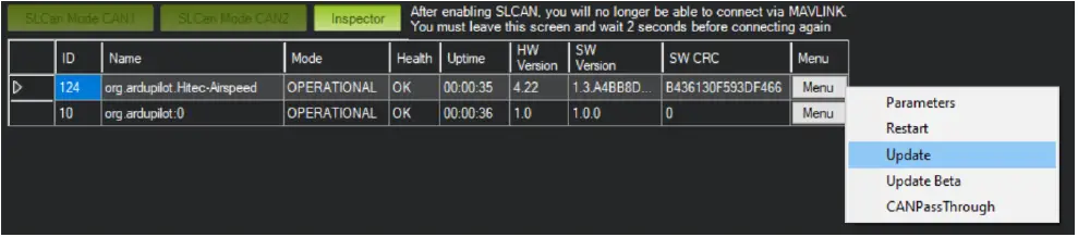
- Once the CAN device corresponding to the Airspeed Sensor appears, expand the menu and choose the “Update” option.

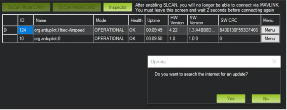
- When prompted, click “Yes” to search the internet for an update or “No” to browse for a firmware file manually.

- The update will be performed, and the device will restart once complete.