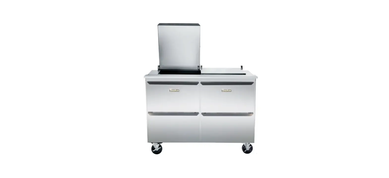
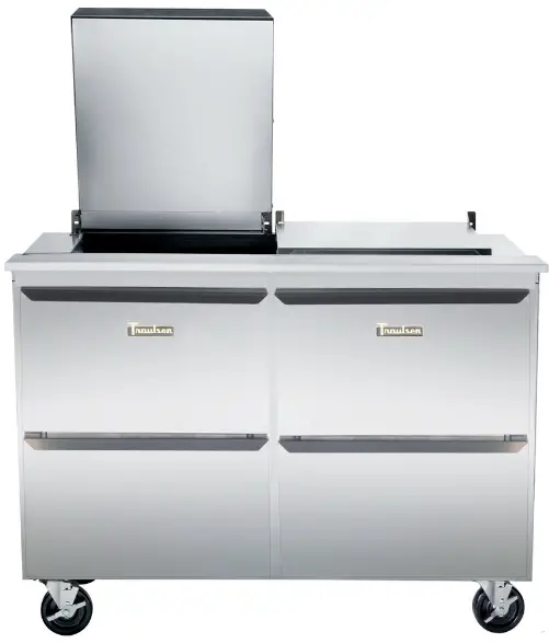
Traulsen UPT6012-DD-SB 60 Inch 4 Drawer Stainless Steel Back Refrigerated Sandwich
Instructions for the installation, operation and maintenance of Traulsen:
Door and Drawer Models Compact Undercounter Refrigerators and Freezers: 27”, 32”, 48” and 60” Compact Prep Tables UPT and UST Series: 27”, 32”, 48” and 60”
This Traulsen unit is built to our highest quality standards. We build our refrigerators this way as a matter of pride. This philosophy has made Traulsen the
leader in commercial refrigeration since 1938. We thank you for your choice and confidence in Traulsen equipment and we know you will receive many years
of utility from this equipment.
All Traulsen units are placed on a permanent record file with the service department. In the event of any future questions you may have, please refer to the model
and serial number found on the name tag affixed to the unit. Should you need service, call us on our toll free number, 800-825-8220 between 7:30 am – 4:30
pm CST, Monday thru Friday. You may also log onto www.traulsen.com for further information. It is our pleasure to help and assist you in every possible way.
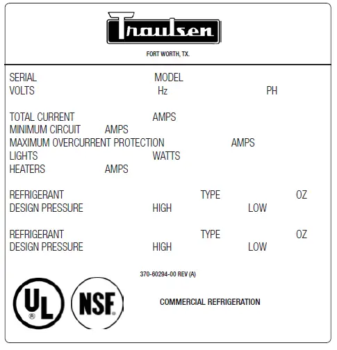
THE SERIAL TAG
The serial tag is a permanently affixed label on which is recorded vital electrical and refrigeration data about your Traulsen product, as well as the model and serial number. This tag is located in the right interior compartment on all standard models.
READING THE SERIAL TAG:
- Serial = The permanent ID# of your Traulsen unit
- Model = The model # of your Traulsen unit
- Volts = Voltage
- Hz = Cycle
- PH = Phase
- Total Current = Maximum amp draw
- Minimum Circuit = Minimum circuit ampacity
- Lights = Light wattage
- Heaters = Heater amperage (Hot Food units only)
- Refrigerant = Refrigerant type used and refrigerant charge
- Design Pressure = High & low side operating pressures
- Agency Labels = Designates agency listings
RECEIPT INSPECTION
All Traulsen products are factory tested for performance and are free from defects when shipped. The utmost care has been taken in crating this product to protect against damage in transit. You should carefully inspect your unit for damage during delivery. If damage is detected, you should save all the crating materials and make note on the carrier’s Bill Of Lading describing the damage. A freight claim should be filed immediately. If damage is subsequently noted during or immediately after installation, contact our customer care team to file a freight claim. There is a fifteen (15) day limit to file freight damage with the carrier. Under no condition may a damaged unit be returned to Traulsen without first obtaining written permission (return authorization). You may contact Hobart/Traulsen customer care at 800-333-7447 to request a return or file a claim.
LOCATION:
Select a proper location for your unit, away from extreme heat or cold. Allow enough clearance between the unit and the side wall in order to make use of the stay open feature at 1200 (self-closing feature operates up to 900). The door(s) must be able to open a minimum of 900 in order to make use of the maximum clear door width.
NOTE: Do not install the cabinet without legs, casters or front ventilated utility base.
PACKAGING:
All Traulsen units are shipped from the factory bolted to a sturdy wooden pallet and packaged in a durable cardboard container. The carton is attached to the wooden skid with the use of large staples. These should first be removed to avoid scratching the unit when lifting off the crate. To remove the wooden pallet, first if at all possible, we suggest that the cabinet remain bolted to the pallet during all transportation to the point of final installation. The bolts can then be removed with a 5/8” socket wrench by tipping or otherwise raising the unit to allow access to them. Avoid laying the unit on its front, side or back for removal of the pallet.
NOTE: Traulsen does not recommend laying the unit down on its front, side or back. However, if you must please be certain to allow the unit to remain in an upright position afterwards for 24 hours before plugging it in so that the compressor oils and refrigerant may settle.
INSTALLING/ADJUSTING LEGS OR CASTERS:
6” High legs are supplied standard for all Traulsen compact undercounter and prep table units. These are shipped from the factory inside a cardboard box which is secured inside the cabinet. Casters in lieu of legs are supplied as an optional accessory for all compact undercounter and prep table models. The casters are “stem” type, and do not require the use of any bolts. When ordered casters are shipped in a separate box.
WARNING: THE CABINET MUST BE BLOCKED AND STABLE BEFORE INSTALLING LEGS OR CASTERS.
Raise up and block the cabinet a minimum of 7” from the floor and thread the legs into the threaded holes on the bottom of the cabinet’s.
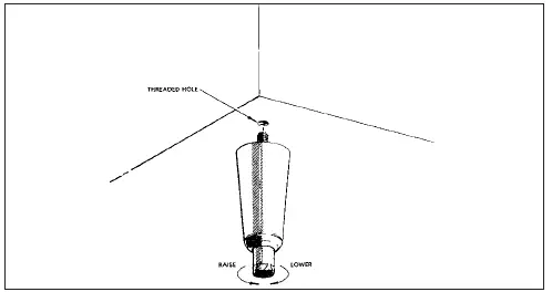
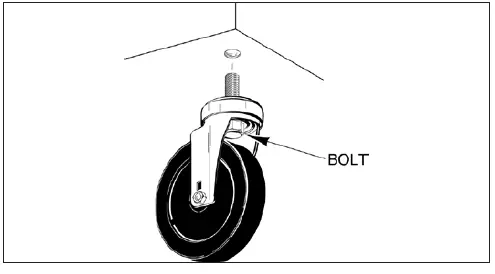
Thread optional casters into the threaded holes on the bottom of the cabinet in the same way. Casters with brakes should be installed at the front.
Level the cabinet using a level or pan of water in the bottom of the cabinet. On units with legs, turn the adjustable feet in or out to level the cabinet side-to-side and front-to-back. Units with casters should be placed on level floors.
NOTE: Traulsen units are not designed to be moved while on legs. If the unit requires moving, a pallet jack or forklift should be used to prevent damage.
SHELF CLIPS FOR DOOR MODELS:
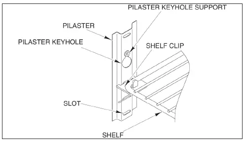
Shelves and shelf clips are shipped with the unit. For each shelf, insert four (4) shelf clips into the pilaster slots at the same height. The shelf clips have a small projection on top which holds the shelf position and prevents it from slipping forwards. After installing shelf clips on pilasters, place shelves on clips.
CORD & PLUG:
All UHT, ULT, UPT & UST models are supplied with a cord and plug attached. It is shipped coiled at the bottom of the cabinet, secured by a nylon strip. For your safety and protection, all units supplied with a cord and plug include a special three-prong grounding plug on the service cord. Select only a dedicated electrical outlet with grounding plug for power source.
NOTE: Do not under any circumstances, cut or remove the round grounding prong from the plug, or use an extension cord.
POWER SUPPLY:
The supply voltage should be checked prior to connection to be certain that proper voltage for the cabinet wiring is available (refer to the serial tag to determine correct unit voltage, see page 1). Make connections in accordance with local electrical codes. Use qualified electricians. Use of a separate, dedicated circuit is required. Size wiring to handle indicated load and provide necessary over current protector in circuit (see amperage requirements on the unit’s serial tag).
CLEARANCE:
It is important for the proper operation and longevity of your Traulsen unit that it have adequate provisions underneath for air supply to the compressor. There are no clearance requirements for the sides, rear or top.
NOTE: Do not install the cabinet without legs, casters or a front ventilate utility base
CUTTING BOARD ASSEMBLY-UPT/UST:
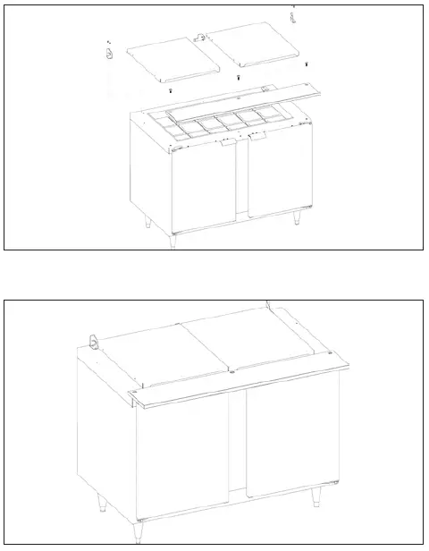
On sandwich prep tables, the cutting board may require assembly at the site. Place cutting board on cabinet, properly align & install three screws to secure in place. The cutting board is field reversible, reverse process to reverse cutting board.
Note: The lid(s)/cover(s) are installed at the factory. No assembly required.
INSTALLING THE STAINLESS STEEL TOP-UHT:
All 27”, 32, 48, and 60” wide compact undercounter models can be supplied with an optional stainless steel top. This must be installed on-site, to do so please follow the directions below
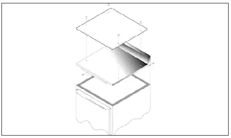
- Peel Off backing and install foam tape (provided) around entire perimeter of the top of the unit.
- A flange is assembled underneath at the front of the counter top. This flange has two screw holes. Screw the two 1/4-20×5/8” screws (provided through the holes in this front flange into the threaded holes in the front of the top edge of the unit.
- Using the five 10-16×1/2” screws provided, screw the bottom of the rear cover plate to the upper rear of the cabinet.
- If the optional polyethylene cutting board top is provided, there are four threaded pins which screw into the four threaded holes in the work top. The four holes in the polyethylene cutting board top fit around the heads of the four pins.
OPERATION
PRESTART CHECKS:
The compressor must float freely before connecting to electrical power. The compressor motor is provided with rubber vibration isolator mounts (no springs). No bolts need to be loosened. Check all exposed refrigera-tion lines to make sure they are not dented or kinked. Check for tubing shifts due to shipping that would cause operating noise, wear, or leaks. Check that condenser fan rotates freely. The refrigeration system should be checked for proper operation before product is stored in the cabinet.
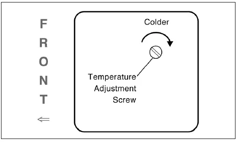
TEMPERATURE CONTROL:
The temperature is set at the factory but local conditions may necessitate slight adjustment. The temperature control shown in below is located on the front side of the evapo-rator housing. To adjust, turn the adjustment screw with a screwdriver a small amount at a time; turning clockwise lowers the temperature. An “OFF” position is fully counterclockwise and interrupts power to the compressor and condenser fan only, not the entire refrigerator.
ULT32 freezer model is equipped with a knob that has a number ranging from 0 to 9. Turning the knob clockwise lowers the temperature, turning the knob coun-terclockwise raises the temperature. O is the “OFF” position. The temperature range of adjustments is -5 to 5 F degrees.
DEFROST CONTROL:
Frozen food storage cabinets are equipped with a defrost timer that provides a 20 minute defrost cycle every 6 hours (four defrost cycles per day).
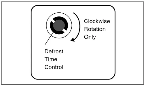
This control can be adjusted to set when the next defrost cycle will start. To adjust the defrost time control, use a coin on the outside slot in the rim of the timer and turn clockwise until the compressor turns off. Continue turning coin clockwise until the compressor restarts. The next defrost cycle will start in about 5 hours 40 minutes. On all models ULT27, ULT48 and ULT60, the defrost time control is located on the front side of the evaporator housing, behind the temperature control adjustment screw. On earlier models ULT48 and ULT60, the defrost time control was accessed through a small round opening on the outside rear of the unit. ULT32 freezer model requires no adjustment. The defrost occurs every 4 hours. It is time initiated and temperature terminated with a time safety backup.
REFRIGERATING PRODUCT:
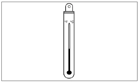
A thermometer is provided inside all UHT, ULT, UPT & UST models. Al-low the cabinet to reach normal operating temperature before loading.
Sandwich Prep models are provided with 1/6 size plastic pans and metal divider bars. When 18 one sixth size pans are ordered, four standard and one wide pan divider/supports are provided to achieve appropriate pan separation. When 24 one-sixth size pans re ordered, six standard and one wide pan divider bars are provided to achieve appropriate pan separation. All other arrangements use all standardwidth pan divider bars.
Drawer models are provided with metal divider bars standard. All 27” wide models are supplied with 2 bars, 32” wide models are supplied with 2 narrow bars and 1 wide bar and 60” wide models are supplied with 2 bars and 1 hook divider bar, per drawer.
CARE AND MAINTENANCE
Exterior stainless steel should be cleaned with warm water, mild soap and a soft cloth. Apply with a dampened cloth and wipe in the direction of the metal grain.
Avoid the use of strong detergents and gritty, abrasive cleaners as they may tend to mar and scratch the surface. Do NOT use cleaners containing chlorine, this may promote corrosion of the stainless steel.
For cleaning the interior, the use of baking soda as described in section V. a is recommended. Use on breaker strips as well as door and drawer gaskets.
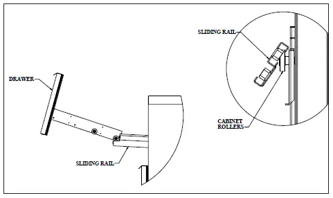
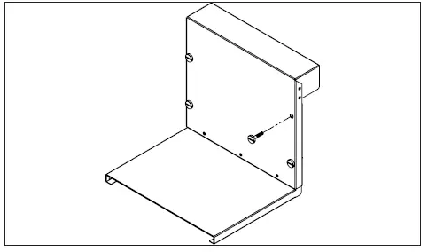
All door models interior fittings are removable without tools to facilitate cleaning. Depending on the level of cleaning, drawer models interior fittings may require a tool to facilitate cleaning. The drawer frame may be removed without tools by simply pulling out and upward. For deeper cleaning the back panel shown in the bubble drawing will require a Phillips screwdriver to be removed.
MISC. OPERATIONS
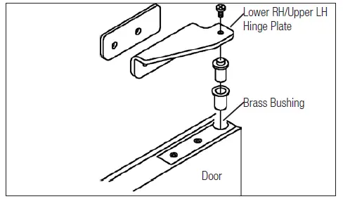
The door(s) on all UHT, ULT, UPT & UST models can be easily rehinged in the field. To begin, open the door to its maximum position. Support the non-hinged end of the door so minimum movement occurs when the bolts from the lower hinge plate are removed. Remove the lower hinge plate and then the door from the top hinge bracket. The hinge plate pin and plastic bushing will remain in the top hinge plate.
PREPARING FOR EXTENDED SHUT DOWN
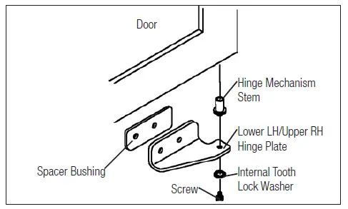
To reinstall the door, position the lower hinge plate into the position of being open 900 to the cabinet. Place the top hinge plate pin in the hole in the top of the door and support the other end of the door for minimal movement. Start the bolts in the lower hinge plate and tighten the bolts enough to hold the door in place. Remove the block from under the end of the door. Adjust the door. If the refrigerator is not to be used for an extended period of time, disconnect the electrical power supply and open the doors. As soon as the cabinet has warmed up to room temperature, wipe out the interior. Leave the doors open and check again to make sure that no moisture has collected on any parts. To restart refrigerator, follow instructions under PRESTART CHECKS and OPERATION.
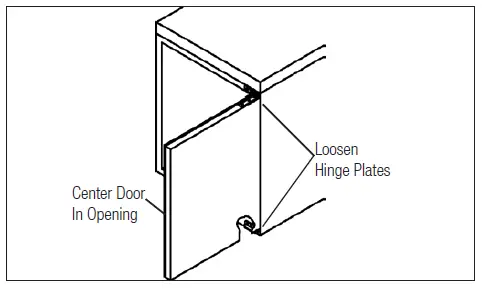
Occasionally the door(s) may require alignment adjustment. To do so, first open the door and loosen the hinge plate screws enough to move the hinges if desired, but the door is held in place. Center the door in the opening. Next level the top hinge plate and tighten the screws. Finally, level the lower hinge plate and tighten the screws.
Remove the old gasket by pulling it out from the gasket retainer. Next, install the four corners of the new gasket by pushing straight in on the gasket until it is hooked behind the gasket retainer. Be careful not to stretch the gasket as it will not return to its original length. Starting at the center of one edge, push the gasket straight in until it is hooked behind the gasket retainer. Proceeding from this point out to the corners, continue pushing the gasket straight into the gasket retainer. Proceed doing the same to each of the remaining edges until the gasket is completely installed.
TROUBLE SHOOTING GUIDE
| PROBLEM | POSSIBLE SOLUTION |
| 1. Condensing unit fails to start. | a. Check if cord & plug has been disconnected. b. Check thermostat temperature setting. |
| 2. Condensing unit operates for prolonged periods or con- tinuously. | a. Are doors or drawers closed properly? b. Dirty condenser or filter. Clean properly. c. Evaporator coils iced. Needs to defrost. |
| 3. Food Compartment is too warm. | a. Check door(s) or drawers and gasket(s) for proper seal. b. Check if a large quantity of warm food was recently added or the door or drawer was kept open for a long period of time. Allow adequate time for the cabinet to recover its normal operating temperature. c. Thermostat setting to high. Readjust per instructions. d. Check that condensing coil is clean. |
| 4. Food Compartment is too cold. | a. Check if a large quantity of very cold or frozen food has recently been added. Allow adequate time for the cabinet to recover its normal operating temperature. b. Adjust the thermostat to a warmer setting. |
| 5. Condensation on exterior surface. | a. Check door(s) or drawer(s) alignment and gaskets for proper seal. b. Condensation on the exterior surface of the unit is perfectly normal during periods of high humidity. |
| 6. Compressor hums & does not start. | a. Call for service. |
SERVICE ASSISTANCE
- Is the electrical cord plugged in?
- Is the fuse OK or circuit breaker on?
- Clean condenser coil
- Is the power switch on?
If after checking the above items and the unit is still not operating properly, please contact an authorized Traulsen service agent. You may obtain the name
of a service agent from the Service Directory page of our web site: www.traulsen.com. Please note, you will be required to register for a login name and
pass code to access our directory. If service is not satisfactory, please contact our in-house service department at:
Traulsen 4401 Blue Mound Road Fort Worth, TX 76106 (800) 825-8220 Traulsen reserves the right to change specifications or discontinue models without notice.
SERVICE SUPPORT INFORMATION:
To purchase replacement parts or to speak to service support for Traulsen and most Hobart refrigeration units please contact our Ft. Worth facility by phone
at 800-825-8220 or fax to 817-740-6748 (parts) or 817-740-6757 (service).
Note: When calling for spare parts or service support, please make sure you have model and serial number of unit available.
To source service support locally follow instructions below for nearest authorized service agent. Please note, you will be required to register for a login name and pass code to access our directory.
- Log onto www.traulsen.com
- Select Contact Us/Dealer Directory (top right of screen)
- Click on Service Directory tab
- Select state by using the drop down box
- Select Go
WARRANTY REGISTRATION:
The warranties for your new Traulsen unit may be registered with us by contacting our Ft. Worth facility directly by phone at 800-825-8220 or you may register on-line. Please note, you will be required to register for a login name and pass code to access our on line registration.
- Log onto www.traulsen.com
- Select Contact Us/Dealer Directory (top right of screen)
- Select Warranty Registration (lower right of screen)
- Fill out information requested
- Select Submit to complete unit warranty registration
WARRANTIES
STANDARD DOMESTIC WARRANTY
TRAULSEN warrants new equipment to the original purchaser, when installed within the United States against defective material and workmanship for one (1) year from the date of original installation. Under this warranty, TRAULSEN will repair or replace, at its option, including service and labor, all parts found to be defective and subject to this warranty. The compressor part is warranted for an additional four (4) years. During this period TRAULSEN will supply replacement compressor(s) if deemed defective, however all installation, recharging and repair costs will remain the responsibility of the owner. This warranty does not apply to damage resulting from fire, water, burglary, accident, abuse, misuse, transit, acts of God, terrorism, attempted repairs, improper installation by unauthorized persons, and does not apply to food loss. For Traulsen units purchased with a remote feature, standard warranty will apply only to those components contained within the unit to the point of connection
of the refrigeration lines leading to the remote condenser.
THERE ARE NO ORAL, STATUTORY OR IMPLIED WARRANTIES APPLICABLE TO TRAULSEN, INCLUDING BUT NOT LIMITED TO, ANY IMPLIED
WARRANTY OF MERCHANTABILITY OR FITNESS FOR ANY PARTICULAR PURPOSE WHICH EXTEND BEYOND THE DESCRIPTION ON THE
FACE HEREOF. TRAULSEN SHALL HAVE NO OBLIGATION OR LIABILITY FOR CONSEQUENTIAL OR SPECIAL DAMAGES, GROWING OUT
OF OR WITH RESPECT TO THE EQUIPMENT OR ITS SALE, OPERATION OR USE, AND TRAULSEN NEITHER ASSUMES NOR AUTHORIZES
ANYONE ELSE TO ASSUME FOR IT ANY OBLIGATION OR LIABILITY IN CONNECTION WITH THE EQUIPMENT OR ITS SALE, OPERATION OR
USE OTHER THAN AS STATED HEREIN.
INTELA-TRAUL® CONTROL WARRANTY
TRAULSEN warrants to the original purchaser of the INTELA-TRAUL® control when installed as part of the Refrigeration/Hot Food Equipment manufactured and sold by TRAULSEN, to be free of defects in material and workmanship under normal service and use for a period of two (2) years from the date of installation. Under this warranty statement, TRAULSEN will repair or exchange at TRAULSEN’S discretion, F.O.B. factory, any part of said control, which proves to be defective. Inspection by the TRAULSEN Service Department of parts claimed defective shall be final in determining warranty status. The warranty is to include repair or exchange of any defective In-Warranty control or part(s) of said control for: Part(s) – Any TRAULSEN INTELA-TRAUL® supplied part(s) found to be defective. Labor – The labor charges from a TRAULSEN certified service agent to effect the repair or exchange of the defective part(s). “Defective Part Return” – All claimed defective part(s) must be returned to TRAULSEN for defect validation within 30 days from the date of the repair. Failure to return all claimed defective part(s) to TRAULSEN will invalidate the warranty claim, this warranty statement, and forfeit payment for those repairs effected. This warranty does not apply to damage resulting from fire, water, burglary, accident, abuse, misuse, transit, acts of God, terrorism, attempted repairs, improper installation by unauthorized persons, and does not apply to food loss, and will not apply if said equipment is located outside The United States.
TRAULSEN warrants to the original purchaser the Refrigeration Equipment manufactured and sold by it to be free from defects in material and workmanship under normal
use and service for a period of one (1) year from date of shipment. Under this warranty, TRAULSEN will reimburse the purchaser for the replacement of any part of said
equipment (excluding dryers & refrigerant gas) which then proves to be defective. This warranty does not apply to damage resulting from fire, water, burglary, accident,
abuse, misuse, transit, acts of God, terrorism, attempted repairs, improper installation by unauthorized persons, and will not apply to food loss.
TRAULSEN’S standard warranty does not apply to Export Sales. Rather, for a period of one (1) year from date of original installation not to exceed Fifteen (15) months from
date of shipment from factory, TRAULSEN: will replace, F.O.B. factory, any defective parts normally subject to warranty. will not cover the cost of packing, freight or labor such costs being the sole responsibility of the dealer. THIS WARRANTY IS IN LIEU OF ALL OTHER WARRANTIES EITHER EXPRESSED OR IMPLIED AND CONSTITUTES TRAULSEN’S FULL OBLIGATION AND LIABILITY. WARRANTIES NOT AVAILABLE ON REMOTE MODELS.
SERVICE PARTS LIST
Note: Part numbers listed are for standard products as currently manufactured. For products manufactured as other than standard, please contact the factory.
| ITEM | DESCRIPTION | PART NUMBER |
| CASTERS | 6” CASTER – 60” MODELS | CASTER 5SET6 |
| 6” CASTER – 27”, 32” & 48” MODELS | CASTER 5SET4 | |
| 4” CASTER – 60” MODELS | CASTER 60SET3 | |
| 4” CASTER – 27”, 32” & 48” MODELS | CASTER SET4IN | |
| 3 1/2” CASTER – 60” MODELS | CASTER SET4 | |
| 3 1/2” CASTER – 27” , 32” & 48” MODELS | CASTER SET3IN | |
| 2 1/2” CASTER – 27” MODELS | CASTER SET2IN | |
| HINGE | REPLACEMENT HINGE | SER-60248-00 |
| REPLACEMENT HINGE CARTRIDGE | SER-60249-00 | |
| SHELVES | SHELF – 27” MODELS | SHELF CPW1 |
| SHELF – 32” MODELS | SHELF CPW2 | |
| SHELF – 48” MODELS (UPPER) | SHELF48 UPPER | |
| SHELF – 48” MODELS (LOWER) | SHELF48 LOWER | |
| SHELF – 60” MODELS (UPPER) | SHELF60 UPPER | |
| SHELF – 60” MODELS (LOWER) | SHELF60 LOWER | |
| SHELF CLIP | SHELF CLIP – ALL MODELS | SER-60269-00 |
| THERMOMETER | THERMOMETER – ALL MODELS | SER-60268-00 |
| TOP, BACKSPLASH | BACKSPLASH TOP – 27” MODELS | CU27TOP BSWO |
| BACKSPLASH TOP – 32” MODELS | CU32TOP BSWO | |
| BACKSPLASH TOP – 48” MODELS | CU48TOP BSWO | |
| BACKSPLASH TOP – 60” MODELS | CU60TOP BSWO |
Note: Part numbers listed are for standard products as currently manufactured. For products manufactured as other than standard, please contact the factory.
| ITEM | DESCRIPTION | PART NUMBER |
| DRAWER 27 COMPACT | DRAWER ASSEMBLY | 550-10234-00 |
| DRAWER TOP | 550-10214-00 | |
| DRAWER BOTTOM | 550-10233-00 | |
| DRAWER FACE ASSEMBLY TOP | 550-10216-00 | |
| DRAWER FACE ASSEMBLY BOTTOM | 550-10216-01 | |
| DRAWER FRAME ASSEMBLY TOP/BOTTOM | 550-10135-01 | |
| DRAWER SUPPORT LEFT | 550-10231-00 | |
| DRAWER SUPPORT RIGHT | 550-10232-00 | |
| DRAWER SLIDING RAIL LEFT | 550-10230-00 | |
| DRAWER SLIDING RAIL RIGHT | 550-10230-01 | |
| DRAWER CROSSRAIL | 550-10215-00 | |
| DRAWER GASKET TOP | 341-60099-02 | |
| DRAWER GASKET BOTTOM | 341-60099-03 | |
| DRAWER ROLLER | 344-41808-01 | |
| DIVIDER | 701-60774-00 | |
| DRAWER 32 COMPACT | DRAWER ASSEMBLY | 550-10236-00 |
| DRAWER TOP | 550-10222-00 | |
| DRAWER BOTTOM | 550-10235-00 | |
| DRAWER FACE ASSEMBLY TOP | 550-10224-00 | |
| DRAWER FACE ASSEMBLY BOTTOM | 550-10224-01 | |
| DRAWER FRAME ASSEMBLY TOP/BOTTOM | 550-10209-01 | |
| DRAWER SUPPORT LEFT | 550-10231-00 | |
| DRAWER SUPPORT RIGHT | 550-10232-00 | |
| DRAWER SLIDING RAIL LEFT | 550-10230-00 | |
| DRAWER SLIDING RAIL RIGHT | 550-10230-01 | |
| DRAWER CROSSRAIL | 550-10223-00 | |
| DRAWER GASKET TOP | 341-60099-04 | |
| DRAWER GASKET BOTTOM | 341-60099-05 | |
| DRAWER ROLLER | 344-41808-01 | |
| DIVIDER NARROW | 701-61258-03 | |
| DIVIDER WIDE | 701-61258-04 | |
| DRAWER 60 COMPACT | DRAWER ASSEMBLY FIRST OPENING | 550-10239-00 |
| DRAWER ASSEMBLY SECOND OPENING | 550-10239-01 | |
| DRAWER TOP | 550-10214-02 | |
| DRAWER BOTTOM | 550-10233-00 | |
| DRAWER FACE ASSEMBLY TOP | 550-10216-00 | |
| DRAWER FACE ASSEMBLY BOTTOM | 550-10216-01 | |
| DRAWER FRAME ASSEMBLY TOP | 550-10135-03 | |
| DRAWER FRAME ASSEMBLY BOTTOM | 550-10135-01 | |
| DRAWER SUPPORT LEFT FIRST OPENING | 550-10231-00 | |
| DRAWER SUPPORT RIGHT FIRST OPENING | 550-10237-00 | |
| DRAWER SUPPORT LEFT SECOND OPENING | 550-10238-00 | |
| DRAWER SUPPORT RIGHT SECOND OPENING | 550-10232-00 | |
| DRAWER SLIDING RAIL LEFT | 550-10230-00 | |
| DRAWER SLIDING RAIL RIGHT | 550-10230-01 | |
| DRAWER CROSSRAIL | 550-10215-00 | |
| DRAWER GASKET TOP | 341-60099-02 | |
| DRAWER GASKET BOTTOM | 341-60099-03 | |
| DRAWER ROLLER | 344-41808-01 | |
| DIVIDER WITH HOOKS | 601-61110-00 | |
| DIVIDER | 701-60774-00 |
HOURS OF OPERATION:
Monday thru Friday 7:30 am – 4:30 pm CST
Traulsen
4401 Blue Moud Road Fort Worth, TX 76106 Phone (800) 825-8220 Fax (817) 740-6757 Website: www.traulsen.com


