

Aria-130
Digital Key Telephone System
| Installation Manual |
Aria Communications
Quadrant Business Park
Unit 3 / 15 Pickering Road
Mulgrave
VIC 3170
ABN : 22 090 723 925
Aria-130
DIGITAL KEY TELEPHONE SYSTEM
CONFIDENTIALITY
The information contained in this manual is the property of Aria Communications Pty. Limited.
The contents of this manual must not be copied, distributed or made available to any third party without the prior written consent of Aria Communications Pty. Limited.
Every effort has been made to ensure that this manual documents the operation of the Aria-130 Digital Key Telephone System.
However, due to the on-going improvement and update of software, Aria Communications cannot guarantee the accuracy of printed material after the date of publication, nor can Aria Communications accept responsibility for errors or omissions.
Revised manuals will be published as needed.
This manual replaces all previous issues.
REVISION HISTORY
| ISSUE | DATE | Contents of Changes | REMARK |
| Field Trial | Nov. 2002 | Initial Document | |
| 1.0 | 10/March/03 | Release Version | |
| 1.1 | 30/Sep/03 | Change System Aria-130 BRI Capacity | |
| 1.2 | 11/11/03 | Add STIB (network side) to capacity chart |
INTRODUCTION
PURPOSE
This manual provides the information necessary to install, operate, and maintain the Aria-130 Digital Key Telephone System. For the system Administration Programming, see the PROGRAMMING MANUAL, which is separately supplied.
REGULATORY INFORMATION
Telephone Company Notification
The Aria-130 Key Telephone System is fully compliant to all of the relevant Australian Communications Authority standards.
Incidence Of Harm
If the carrier determines that the customer provided equipment is faulty due to any possibly causing harm or interruption in service to the telephone network, it should be disconnected until repair can be effected. If this is not done, the carrier may temporarily disconnect service.
Changes In Service
The local Carrier may make changes in its communications facilities or procedures. If these changes could reasonably be expected to affect the use of the Aria-130 system or compatibility with the network, the carrier is required to give advanced written notice to the user, allowing the user to take appropriate steps to maintain telephone service.
Maintenance Limitations
Maintenance on the Aria-130 Digital Key Telephone System must be performed only by Aria Communications it’s authorized Dealers and authorized agents. The user is not authorized to make any changes and/or repairs except as specifically noted in this manual. Unauthorized alternations or repairs may affect the regulatory status of the system and may void any remaining warranty.
Notice Of Radiated Emissions
The Aria-130 Digital Key Telephone System complies with rules regarding radiation and radio frequency emission as defined by local regulatory agencies. In accordance with these agencies, you may be required to provide information such as the following to the end user.
WARNING : “This equipment generates and uses R.F.energy, and if not installed and used in accordance with the Instruction Manual, it may cause interference to radio communications. It has been tested and found to comply with the appropriate limits for a telecommunication device. The limits are designed to provide reasonable protection against such interference, when operated in a commercial environment.
Operation of this equipment in a residential area could cause interference, in which case the user, at his own expense, will be required to take whatever measures may be required to correct the interference.”
Hearing Aid Compatibility
The Aria-130 Digital Key Telephone has been designed to comply with the Hearing Aid Compatibility requirements as defined in ACA Technical Standards ACA TS004-1997.
Notice Of Replacement With Lithium Battery
CAUTION
· There is danger of an explosion if the battery is incorrectly replaced.
· Replace only with the same or equivalent type recommended by the manufacturer.
· Dispose of used batteries according to the manufacturer’s instructions.
GENERAL DESCRIPTION
INTRODUCTION
The ARIA-130 Digital Key Telephone System is a fully digital hybrid Key Telephone System, designed to meet the telecommunication needs of medium sized business offices.
The ARIA-130 System incorporates state of the art digital technology for command processing and voice switching, utilizing a Pulse Code Modulation/Time Division Multiplexing (PCM/TDM, “A” law or “u” law) distributed switching matrix.
The ARIA-130 achieves a high level of flexibility by 1) employing a Universal Card Slot architecture with the 1’st and the 2’nd cabinet to house plug-in Printed Circuit Boards, and 2) providing support for different types of instrumentation.
The KSU of ARIA-130 is a wall-mounted cabinet that houses the MB(Mother Board) and card slots for the CO line/Key Station/SLT/ISDN/LAN interface boards, and other useful boards. There are two-story KSU in the system. The first KSU is basic KSU. On the other hand, the second one is the expansion KSU. MPB should be installed in the fixed MPB slot in the first KSU. There is a built-in PSU that is installed in the fixed PSU position in two KSU.
The system architecture has been designed to allow a high level of software control over the system’s hardware. The software incorporates a vast array of features and capabilities including PC Database Administration, Auto Route Select, ACD, etc.
The ARIA-130 system supports a combination of Digital Keysets (KD, KD/E, KD/S, KD/C, LKD series), various kinds of ISDN terminals, and wireless terminals as well as analogue single line devices. With the keysets, commonly used features are activated by direct button selection. Additionally, many functions may be accessed by dialing specific codes or optionally, by assigning these dial codes to Flexible Buttons on the keyset. In addition to key telephones, an array of optional terminals is available including DSS/DLS Console, Intercom/Door Box.
With the flexibility of the ARIA-130 extensive feature content, and the capability to use an array of instruments, the ARIA-130 can be tailored to meet the short and long term needs of the most demanding customer requirements.
SYSTEM CAPACITY
The following table and chart provide system capacities and display the configuration flexibility of the system.
System Capacity
KSU contains six universal slots and one MPB slot.
There is a built-in PSU(Power Supply Unit) .
| PSU | +5V | 5V | 30V | Battery |
| ARIA130 PSU(120W) | 4A | 0.5A | 3A | 0.5A |
Table 2.2.1 Power Supply Capacity
Max capacity of system is described in the Table 2.2.2 max. call capacity of system, and system capacity is in the Table 2.2.3 system capacity.
| KSU | Max Port (Number of Boards) | |||||||
| Extension | Network Side | |||||||
| So (STIB) | DKTU (DTIB24) | SLT (SLIBII) | PRI (PRIB) | GDK-100 BRI (BRIB) | So (STIB) | LDK-130 BRI (BRIB/BRIU) | LCO (LCOB8) | |
| 1’st KSU | 40(5) | 48(2) | 48(4) | 40(2) | 40(5) | 40(5) | 16(2) | 40(5) |
| 1’ KSU + 2nd KSU | 40(5) | 96(4) | 96(8) | 40(2) | 40(5) | 40(5) | 16(2) | 40(5) |
Table 2.2.2 System Max. call capacity
| Description | Capacity | Description | Capacity | |||
| Time Slots | 1’st KSU + | 144 | Paging | External | 3 (MPB:1, MISB:2) | |
| (note A) | 2’nd KSU | Zone | Internal | 15 | ||
| Cabinet(KSU) | 2 | System Speed Dial | 1500(24digits) | |||
| Serial Port(RS-232C) | 2 (MPB:2) | Station Speed Dial | 100(24digits)per station | |||
| Alarm/Door bell input | 2 (MPB:1,MISB:1) | Last Number Redial | 10 | |||
| External Control Contact | 6 (MPB:2, MISB:4) | Save Number Redial | 1 | |||
| Music Source Inputs | 3 (MPB:1, MISB:2) | DSS/DLS Console | 3 | |||
| DTMF Receivers | 46 (note B) | SMDR | 5000 | |||
| Power Fail Circuit | 40 | CO Line Group | 24 | |||
| Intercom Group | 5 | Hunt/UCD Group | 15 | |||
Table 2.2.3 System capacity
* Note A ;
-. Time slots are used to allocated flexibly to support each function PSTN, ISDN, VMIB, WTIB, MOH, Paging, Modem, DTMF detection, etc.
-. Maximum ports of ARIA-130 are 132.
* Note B ;
-. Option : 2chs/DTRU, 4chs/DTRUII, 4chs/DTRU4, 2chs/MPB
· Note : For the number of ports in a board, see the section 2.4.
Aria-130 Maximum Port Capacities
When considering total port of the capacities of the system, it is necessary to consider the type of PMU that will be installed.
The Aria-130 has four types of PMU: –
- PMU 1 & 2
- ASMU 1 & 2
PMU 1 & 2 do not support advanced features such as QSIG, PC Attendant and CTI.
ASMU 1 & 2 do support advanced features such as QSIG, PC Attendant and CTI.
PMU 1 and ASMU 1 both have a maximum of 88 ports. (Non-DECT).
PMU 2 and ASMU 2 both have a maximum of 132 ports. (Non-DECT).
So, when considering port capacities only, PMU 1 and ASMU 1 are the same and PMU 2 and ASMU 2 are the same.
PMU / ASMU summary
| No of KSUs supported | Supports Advanced Features (QSIG, PC Attendant, CTI) | Port Capacity | Flash ROM size | |
| PMU 1 | 1 | No | 88 port | 4 MB ROM |
| ASMU 1 | 1 | Yes | 88 port | 8 MB ROM + 2 MB (SMEMU) |
| PMU 2 | 1 or 2 | No | 132 port | 4 MB ROM |
| ASMU 2 | 1 or 2 | Yes | 132 port | 8 MB ROM + 2 MB (SMEMU) |
Capacities without WTIB installed
| PMU 1 (1 KSU only) | PMU 2 (1 or 2 KSUs) | |
| Max No. of wired stations | 48 | 96 |
| Max No. of CO’s | 40 | 40 |
| Max port capacity | 88 | 132 |
Capacities with WTIB installed
| PMU 1 (1 KSU) | PMU 2 (1 or 2 KSUs) | |
| Max No. of wired stations | 48 | 96 |
| Max No. of un-wired stations | 40 | 80 |
| Max No. of combined stations | 88 | 128 (note 1) |
| Max No. of CO’s | 40 | 40 |
| Max port capacity | 128 | 132 |
Note 1 – this is the maximum number of stations possible.
System Configuration Chart
Overview
The maximum capacity of the system configured only with the wired extensions will be limited by the physical condition of the system, e.g. the quantity of slots and cards limitation. System configuration charts are as follows;

Figure 2.2.1 System configuration charts
SYSTEM SPECIFICATIONS
The following Tables provide general system specifications.
Dimension And Weight
| Item | Height(mm/in) | Width(mm/in) | Depth(mm/in) | Weight(kg/lbs) | |
| KSU | 406 | 440 | 230.5 | 13.2 | |
| Digital Keyset | 236/9.3 | 192/7.6 | 84/3.3 | 1.5/3.3 | |
| Digital DSS/DLS Console | 236/9.3 | 125/4.9 | 62/2.4 | 0.9/2.0 | |
| Digital ICM/Door Box | 45/1.8 | 140/5.5 | 100/3.9 | 0.5/1.1 | |
| Digital Data Module | 37/1.5 | 175/6.9 | 148/5.8 | 1.5/3.3 | |
| Base Station(GDC-330B) | 170 | 220 | 57 | 0.46 | |
| Wireless | GDC-33xH | 145 | 50 | 35 | 0.15 |
| Terminal | GDC-340H | 131 | 49 | 32 | 0.102 |
Table 2.3.1 Dimension and weight
Environment Specification
| Item | Degrees (℃) | Degrees (℉) |
| Operation Temperature | 0~40 | 32~104 |
| Optimum Operation Temperature | 20~26 | 68~78 |
| Storage Temperature | 10~70 | 32~158 |
| Relative Humidity | 0~80% non condensing | |
Table 2.3.2 Environment specification
Electrical Specification
System Electrical Specification
| Item | Specification |
| 1. PSU | |
| – AC Voltage Input | 110 or 220 +/- 10% Volt AC @48~63Hz |
| – AC Power | 127W |
| – AC Input Fuse | 4.0 amp @ 220Volt AC 8.0 amp @ 110Volt AC |
| – DC Output Voltage | + 5, – 5, + 30Volt DC |
| 2. Battery Backup | |
| – PSU Input Voltage | 24Volt DC |
| – PSU Battery Fuse | 10.0amp @250Volt AC |
| – Charging Current | Max. 0.5A |
| 3. External Relay Contact | 1amp @24Volt DC |
| 4. Music Source Input | 0dBm @600ohm |
| 5. External Paging Port | 0dBm @600ohm |
Table 2.3.3 System Electrical specification
Base Station Specification (GDC-330B)
| Item | Specification |
| Power feeding | +30V DC |
| Transmission Max Power | 250mW |
| Access Method/Duplex | TDMA/TDD |
| Frequency Band | 1,880 ~ 1,900MHz |
| Channel Spacing | 1.728MHz |
| Modulation | GFSK |
| Data rate | 1.152Mbps |
| Max. Base Station distance from the WTIB | 600m (twisted 2-pair cable) |
Table 2.3.4 Base Station specification
Max. Station Distance From The System
| Item | AWG 22 (m/kft) | AWG 24 (m/kft) |
| Digital Keyset | ||
| DTIB12/DTIB24/DSIB | 500 / 1.6 | 330 / 1 |
| Single Line Telephone | ||
| SLIB24/SLIBII/SLIB2E/DSIB | 2,500 / 8.2 | 1,600 / 5.2 |
| SLIB48 | 5,000 / 16.5 | 3,300 / 10 |
Table 2.3.5 Max. Station Distance from the System
Co Loop Specification
| Item | Specification |
| Ring Detect Sensitivity | 40Vrms @16~30Hz 30Vrms @30~37Hz |
| DTMF Dialing Frequency Deviation Signal Rise Time Tone Duration, on time Inter-digit Time | Less than +/- 1.8 % Max. 5ms Min. 50ms Min. 30ms |
| Pulse Dialing Pulse Rate Break/Make Ratio | 10 pps 60/40% or 66/33% |
Table 2.3.6 CO loop specification
WHTU Specification
| Item | Specification |
| Max. Transmission Power | 250mW |
| Modulation Method | GFSK |
| Frequency Band | 1,880MHz ~ 1,900MHz |
Table 2.3.7 WHTU specification
Specification for VOIB/VOIU
| Item | Specification |
| LAN Interface | 10 / 100 Base-T Ethernet(IEEE 802.3) |
| Speed | 10 Mbps or 100 Mbps(Auto-Negotiation) |
| Duplex | Half Dulpex or Full Duplex(Auto-Negotiation) |
| VoIP Protocol | H.323 Revision 2 |
| Voice Compression | G.711 / G.729A / G.729B / G.723.1 / G.726 / G.727 |
| Voice/Fax Switching | Automatic |
| Echo cancellation | G.168 |
Table 2.3.8 VOIB/VOIU Specification
Specification for LANU
| Item | Specification |
| LAN Interface | 10 / 100 Base-T Ethernet (IEEE 802.3) |
| Speed | 10 Mbps |
| Duplex | Half Duplex or Full Duplex (Auto-Negotiation) |
Table 2.3.9 LANU Specification
SYSTEM COMPONENTS
The following table shows the available slots in which every card can be installed. Some boards for GDK-100/ARIA-300 can be used in ARIA-130 system. Others are used in only ARIA-130 system.
| No | Board | Number | Slot Position | Description | |
| Name | of Ports | 1’st KSU | 2nd KSU | ||
| 1 | KSU | Key Service Unit | |||
| 2 | PSU | PSU | PSU | Power Supply Unit, 120W | |
| 3 | MPB | MPB slot | Main Processor Board | ||
| 4 | PMU1 | 1 | MPB | Program Module for only 1st KSU | |
| 5 | PMU2 | 1 | MPB | Program Module for both 1st and 2nd KSU | |
| 6 | ASMU1 | 1 | MPB | Program Module for TAPI, PC-ATTD, Networking (support 1st KSU only) | |
| 7 | ASMU2 | 1 | MPB | Program Module for TAPI, PC-ATTD, Networking (support 1st & 2nd KSU ) | |
| 8 | MODU | 1 | MPB | 33.6Kbps Internal Modem | |
| 9 | SIU | 1 | MPB | Serial Interface Unit | |
| 10 | DMEMU | 1 | MPB | 16Mbyte EDO-DRAM Module(S/W download) | |
| 11 | LANU | 1 | MPB | 10/100 Mbps Ethernet Interface Unit | |
| 12 | MISB | 6 only | Miscellaneous Board | ||
| 13 | DTIB12 | 12 | 1~6 | 1~6 | Digital Terminal Interface |
| 14 | DTIB24 | 24 | 1~6 | 1~6 | Digital Terminal Interface |
| 15 | SLIB24 | 6 | 1~6 | 1~6 | SLT Interface(+24V Feed) |
| 16 | SLIB48 | 6 | 1~6 | 1~6 | SLT Interface(-48V Feed), Maximum 2 cards per a cabinet. |
| 17 | SLIBII | 12 | 1~6 | 1~6 | SLT Interface (-28V Feed) |
| 18 | SLIB2E | 12 | 1~6 | 1~6 | SLT Interface |
| 19 | DSIB | 12 | 1~6 | 1~6 | Digital Terminal(6) and SLT Interface (+24V Feed) |
| 20 | LCOB | 4 | 1~6 | 1~6 | Loop Start CO Interface |
| 21 | LCOB8 | 8 | 1~6 | 1~6 | Loop Start CO Interface |
| 22 | ARIA-300 STIB | 4 (8B) | 1~6 | 1~6 | ISDN So/To Interface (2B+D) |
| 23 | ARIA-300 BRIB | 4 (8B) | 1~6 | 1~6 | ISDN Basic Rate Interface (2B+D) |
| 24 | ARIA-300 PRIB | 1 (30B) | 1~6 | 1~6 | ISDN Primary Rate Interface(30B+D) |
| 25 | ARIA-130 BRIB | 2 (4B) | 1~6 | 1~6 | ISDN Basic Rate Interface (2B+D) |
| 26 | ARIA-130 BRIU | 2 (4B) | ARIA-130 BRIB | ISDN Basic Rate Interface (2B+D) | |
| 27 | ARIA-130 PRIB | 1 (30B) | 1~6 | 1~6 | ISDN Primary Rate Interface(30B+D) |
| 28 | VMIB | 4 | 1~6 | 1~6 | Voice Mail Interface Board |
| 29 | FMEU | 4 | VMIB | Flash Memory Expansion Unit (32MB) | |
| 30 | VCEU | 4 | VMIB | Voice Channel Expansion Unit | |
| 31 | WTIB | 4 | 1~6 | 1~6 | Wireless Terminal Interface Board |
| 32 | WTIU | 4 | WTIB | Wireless Terminal Interface Unit | |
| 33 | EMIB | 4 | 1~6 | 1~6 | E&M Interface Board – India only |
| No | Board | Number | Slot Position | Description | |
| Name | of Ports | 1’st KSU | 2nd KSU | ||
| 34 | VOIB | 4 | 1~6 | 1~6 | Voice Over Internet Protocol Interface Board |
| 35 | VOIU | 2 | VOIB | Voice Over internet protocol Interface Unit | |
| 36 | PLLU | 1 | MPB | Phase Lock Loop Unit for ISDN cards | |
| 37 | MSGU | 6 | SLIB24, DSIB | Message Waiting Unit | |
| 38 | MSGU48 | 6 | SLIB48, SLIB2E | Message Waiting Unit | |
| 39 | MSGUII | 12 | SLIBII | Message Waiting Unit | |
| 40 | DTRU (GDK-34) | 2 | SLIB24,SLIB48,DSIB LCOB | DTMF Receiver Unit | |
| 41 | DTRUII | 4 | SLIBII | DTMF Receiver Unit | |
| 42 | DTRU4 | 4 | LCOB8,SLIB2E,SLIBII | DTMF Receiver Unit | |
| 43 | CPTU/A | 2 | LCOB | Call Progress Tone Detection : 305Hz~640Hz | |
| 44 | CPTU4 | 4 | LCOB8 | Call Progress Tone Detection | |
| 45 | CMU (GDK-162) | 1 | LCOB | Call Metering Unit (16K,12PR,50PR) | |
| 46 | CMU4 | 4 | LCOB8 | Call Metering Unit (12/16PR,50PR) | |
| 47 | RGU6 | 10 SLTs | Ring Generator (25Hz) : Sine Wave, Internal | ||
| 48 | TERM (GDK-162) | 100 ohm Termination for BRI and STI | |||
| 49 | MOHU | Connected to SLT port | External Music On Hold Unit | ||
Table 2.4.1 System Card Description
The following Fig 2.4.1 System configuration diagram shows the ARIA-130 system configuration for all kinds of board in this system that includes the existing boards for the GDK-100/ARIA-300 system and the developed new boards.
E
x
i
s
t
i
n
g
CO/Extension Board
-. LCOB : Analog CO. Interface B/D (4 ports)
-. GDK-100 PRIB : ISDN PRI Board (30 channels)
-. GDK-100 BRIB : ISDN BRI Board (8 channels)
-. STIB : ISDN S/T Interface (8 channels)
-. DTIB : Digital KTU Interface B/D(12,24 ports)
-. SLIB24/48 : Single Line Tel Interface B/D(6 ports)
-. DSIB : 6 Digital KTU and 6 SLT Interface B/D
(12 ports)
-. SLIBII : Single Line Tel Interface B/D (12 ports)
-. EMIB : E&M Interface Board (4 chs)
-. WTIB : DECT Interface B/D (4Cell +Opt 4Cell)
-. WTIU : DECT option B/D (4 Cell )
-. SLIB2E : 12 port SLT Interface B/D
-. VOIB : VOIP Interface B/D
-. VOIU : VOIP Interface Unit (2 chs)
-. LCOB8 : 8 port CO Interface B/D
-. VMIB : Voice Mail Interface B/D
(8 chs ,max.10Hour)
-. TLIB : Tie Line Interface Board (4chs, India only)
– ARIA-130 BRIB : ISDN BRI Board(4 channels)
– ARIA-130 BRIU : Option ISDN BRI Unit(4 channels) – ARIA-130 PRIB : ISDN PRI Board(30 channels)
N
e
w
– . KSU
. MPB
. PSU: 127W
. Universal SLOT : 6 EA
KSU
Other Option Board
N
e
w
E
x
i
s
t
i
n
g
-. DTRU : DTMF Receiver Unit (2 chs)
-. CMU : Call Metering Unit
(16KHz,12PR,50PR)
-. PFTU : Power Failure Transfer Unit (6 circuits)
-. DTRUII : DTMF Receiver Unit (4 chs)
-. CPTU A/B : Call Progress Tone detection Unit
(2 chs)
-. RGU6 : Ring Generator Unit ( Int 25Hz)
-. DTRU4 : DTMF receiver unit (4 chs)
-. CPTU4 : Call Progress Tone detection Unit
(4 chs)
-. CMU4 : Call Metering Unit (4 chs)
-. FMEU : Flash Memory Expansion Unit(32MB)
-. VCEU : Voice Channel Expansion Unit(4 ch.)
-. MSGU/MSGUII/MSGU48 : message wait unit
-. MODU : Modem Unit (33.6kbps)
-. SIU : Serial Interface Unit
-. DMEMU : DRAM Unit(16 Mbyte)
-. LANU : LAN Interface Unit
-. SMEMU : SRAM Unit(2 Mbyte)
-. PLLU : Phase Lock Loop Unit
-. Digital KTU
. KD/E and LKD series
. DSS, Phone Box
-. SLT, Fax, Modem, TAD
-. Wireless Terminal
. GDC-330H,335H,340H
Terminal
Figure 2.4.1 System Configuration
KSU (Key Service Unit)
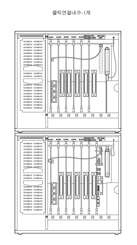
The KSU is a metal frame cabinet designed for wall mounting. It contains a back plane with 12 connectors which are 6 universal slots, MPB slot, PSU, PFTU, RGU, CN11(clock chain) and connector for Link cable. ARIA-130 system is 2-story KSU consisted of the 1’st and 2’nd KSU. It’s possible to install all kinds of boards according the Table 2.4.1. Cable ties are located on the front edge of the lower card rail to allow connecting cables for the station boards, CO interface boards, and MISB to be neatly installed. The connecting cables for the stations and CO Lines exit through the outlet in the bottom of KSU and can be connected to the MDF or to a user installed termination point.
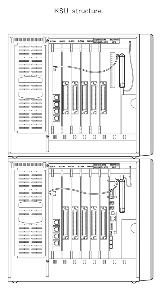
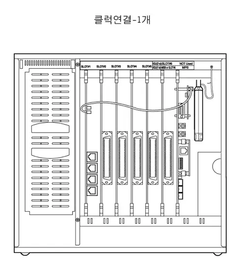
Figure 2.4.2 KSU structure
ARIA-130 MB Iss: Rev:
RGU
PFT
U
SLOT1
SLOT2
SLOT3
SLOT4
SLOT5
SLOT6
MPB
Figure 2.4.3 Board Configuration of MB
MB contains various kinds of connectors as in the Fig 2.4.3 Board Configuration of MB. There are six universal slots in the MB(SLOT 1~6). Any kind of peripheral card can be installed in the universal slot. RGU6 can be installed in the right bottom side of KSU through RGU connector on MB. PFTU is connected to the PFTU connector on MB.
PSU (Power Supply Unit)
A Power Supply Unit, PSU, is supplied with KSU. The PSU converts commercial AC power (110 – 127 / 220 – 240V AC @ 48~63Hz) to DC voltages, regulates the voltages, and provides the appropriate DC voltages to the back plane for distribution to other system components. Three DC outputs are provided : ±5V DC, +30V DC. A red LEDs in the KSU side panel indicate the presence of +30V DC.
The PSU includes circuitry to charge externally connected 24 volt batteries and controls operation of the battery back-up circuits. And the PSU will provide system operating voltages from the batteries if commercial AC power fails. In addition, battery back-up control circuitry is incorporated in the PSU to disconnect the batteries prior to a deep discharge or over-charged.
RGU (Ring Generator Unit)
The Ring Generator Unit provides the ring voltage to the SLIB circuits to ring the SLT. Also the RGU provides the input to the Message Wait source on the SLIB cards. The output of the RGU is 65V AC, 25 Hz. The RGU6 can support simultaneous ringing for 10 SLTs. The internal RGU is fitted on the lower right side panel inside cabinet.
PFTU (Power Failure Transfer Unit)
The PFTU provides the relay contacts for transfer of 6 CO Lines to 6 SLTs in the event of a power or processor failure. The PFTU is installed outside of the KSU and up to 5 PFTU modules can be connected to the KSU with the cascade connection of control wire. The PFTU is equipped with a manual switch that activates the Power Failure Transfer mode for testing purpose.
A 2-pin connector with screws is fitted for the control signal. And a RJ21 type male connector is fitted for the connection between CO line, CO interface circuit, SLT interface circuit and SLT.

Figure 2.4.4 PFTU Configuration
MPB (Main Processor Board)
ALARM
1
2
3
4
5
6
7
8
PMU
CN17
CN1
CN2
DBID II
GSXD
CN9
CPU
S3C4530A
CN10
DMEMU
SMEMU
PLLU
CN16
OFF
Serial Port
PJ 1
Ext. MOH
PJ 2
Ext. PAGE
SIU / MODU
RLY1
JTAG
connector
Battery
Switch
ARIA-130 MPB
LANU
RLY2
Figure 2.4.5 MPB Configuration
The MPB controls and manages the communication between peripheral interface, supervises all resources in the system, controls the gain adjustment of PCM signal, generates system tone and manages call processing of the system.
The MPB, incorporates the system’s RAM, master clock, 1 external MOH port, 1 internal MOH source, 1 external paging port, 1 RS-232C port, 1 alarm port, 2 relay contacts and RTC as well as the system’s PCM voice processing and main micro-processor. The micro-processor is a 32 bit high speed RISC CPU which receives and transmits signaling information from/to other PCBs, controls feature activation, and PCM time-slot interchange. 2Mbytes of SRAM which are associated with the system database and the Real-Time-Clock are protected from power loss by a long life high energy lithium battery. On board ROM contains PCM tone, gain table etc. needed for the digital voice processing.
The 4 Mbytes of flash ROM on PMU1and the 8 Mbytes of flash ROM on PMU2 contain basic system operating software.
MODU(MODEM Unit), LANU(LAN Interface Unit), SIU(Serial Interface Unit), SMEMU(SRAM Memory Unit), DMEMU(DRAM Memory Unit) and PLLU can be installed on MPB, if required.
MPB should be installed only in the MPB slot of the 1st KSU.
Add-on boards: MODU, LANU, SIU, SMEMU, DMEMU, PLLU
MISB (Miscellaneous Board)
The MISB incorporates the circuitry and interfaces for common optional features including:
- External Paging 2 ports
- External Control Contacts 4 contacts
- External BGM & MOH 2 ports
- Alarm/Door Detection 1 input
- RS-232C(optional SIU) Not Available
A RJ21 type female connector is mounted on the front edge of the MISB for the connection to above circuits.
MISB can be installed only in the slot No.6 of the 1st KSU.
Add-on board: None
VMIB (Voice Mail Interface Board)
Voice Mail Interface Board (VMIB) provides announcements for the system’s ACD/UCD features as well as the System Voice Prompts and Recorded User Greetings. Following table shows the capacity of memory, ADPCM channel of VMIB, and its optional board.
| Item | Basic | Option(for expansion) | Maximum Capacity | |
| a board | a system | |||
| Channel | 4 channels | 4 channels | 8 channels | 16 channels |
| System Voice Prompt ACD/UCD Announcement User Greeting | 300 min. | 300 min. | 600 min. | 1200 min. |
Table 2.4.2 Capacity of Memory, ADPCM channel of VMIB
- VMIB allows a FMEU or a VCEU to be expanded.
- ARIA-130 allows 2 VMIB boards to be installed.

There are two option boards, one is VCEU for voice channel expansion and the other is FMEU for flash memory expansion.
VMIB can be installed in the universal slot No 1~6 in any KSU.
Extension Boards
The various types of ARIA-130/ARIA-300/GDK-100 Extension Boards have capable of supporting various types of terminals as followings,
| Board Name | Function | Remark |
| DTIB12 | Provides 12 Digital Terminal interfaces | 2 wire |
| DTIB24 | Provides 24 Digital Terminal interfaces | 2 wire |
| SLIB24 | Provides 6 SLT interfaces with a line voltage of +24V. | 2 wire |
| SLIB48 | Provides 6 SLT interfaces with a line voltage of -48V. | 2 wire |
| SLIBII/SLIB2E | Provides 12 SLT interfaces with a line voltage of -28V. | 2 wire |
| DSIB | Provides 6 Digital Terminals and 6 SLTs with a line voltage of +24V. | 2 wire |
| WTIB/WTIU | Be capable of accommodating up to 8 Base Stations. (up to 64 wireless terminals) | 4 wire |
| STIB | Be capable of accommodating up to 4 ISDN BRI S interfaces, 8 B channels. (Each interface is To/So switch-able port) | 4 wire |
Table 2.4.3 Extension boards
DTIB12/DTIB24 (Digital Terminal Interface Board 12/24)
DTIB allows the LGE proprietary digital terminals to be connected. DTIB provides 2-wire interfaces for terminal connection and three versions according to the capacity are available;
| Board Name | DKT interface circuit | SLT interface circuit | Remarks |
| DTIB12 | 12 ports | None | |
| DTIB24 | 24 ports | None | |
| DSIB | 6 ports | 6 ports | See clause 2.4.8.5 |
Table 2.4.4 Capacity of digital terminals
There are KD, KD/E, KD/C, LKD series DKTU, KD and KD/E DSS, Digital Phone box, and external CTI module as LG digital terminals. KD, KD/(E)C, external CTI module and Data Module are not available now due to the production stop.
See clause 2.4.12.3 2B-module and clause 2.4.12.4 GDK-PC phone on section 2 for more details regarding 2B-module and CTI module.
Digital Interface Board provides digital voice and data communications to/from digital terminals. The board allows for either 1 or 2 bearer channels from a single hardware interface under the control of system software.
A industry standard RJ21 type female connector is mounted on the front edge of the PCB for connection to the station interfaces. In addition, one LED is mounted on the PCB to indicate the in use state of the connected terminals. It will turn on when one or more ports are busy.
DTIB12/DTIB24 can be installed in the universal slot No. 1-6 in any KSU.
SLIB24/SLIB48 (Single Line Interface Board With 6 Ports)
SLIB allows single line analog devices to be connected.
Five kinds of SLIB boards are available in ARIA-130 system;
| Board Name | Interface circuit | Feed voltage | Remark |
| SLIB24 | 6 ports | +24V DC feed | |
| SLIB48 | 6 ports | -48V DC feed | Maximum 2card in each KSU |
| SLIBII | 12 ports | -28V DC feed | See clause 2.4.8.3 |
| SLIB2E | 12 ports | -28V DC feed | See clause 2.4.8.4 |
| DSIB | 6 ports | +24V DC feed | See clause 2.4.8.5 |
Table 2.4.5 Capacity of SLT boards
DSIB provides 6 digital terminal interfaces and 6 single line analog interfaces. For SLIB II and DSIB, see the parts of SLIBII and DSIB in this section.
SLIB24/SLIB48 are capable of accommodating up to 6 single line analog devices. The boards are configured with hybrid circuit and CODEC; converts A/D and D/A signal. SLIB24/SLIB48 allow the SLT access to CO Lines connected to the system, other stations, and most features of the system through the use of dial codes. Connections to the SLIB are made through RJ21 type female connector.
The SLIB24/SLIB48 can be equipped with a Message Wait source (optional MSGU for SLIB24 or MSGU48 for SLIB48), which activates a lamp in the SLT, if so equipped. The Message Wait source sends 90V DC signal to the SLT illuminating the MW lamp. A Ring Generator Unit is required in the cabinet where a SLIB is installed. An optional DTMF receiver unit (DTRU) can be installed on the SLIB24/SLIB48.
The SLIB24 allows a Single Line Telephone to be connected up to 2.5 Kilometers (8,200 feet, loop resistance: 490 ohm) from the system using 22 AWG wire. The SLIB48 allows a SLT to be connected up to 5 Kilometers (16,500 feet, loop resistance: 790 ohm) from the system using 22 AWG wire. See the Table 2.3.5.
In addition, one LED is mounted on the PCB to indicate the in use status of ports connected to SLIB. It will turn on when one or more ports are busy.
The SLIB24/SLIB48 can be installed in the universal slot No. 1-6 in any KSU.
Add-on boards: DTRU, MSGU (for SLIB24), MSGU48 (for SLIB48)
SLIB II (Single Line Interface Board with 12 Ports)
SLIB II provides the capability to connect 12 single line analog terminals to the system with appropriate A/D and D/A conversions. SLIB II is -28V DC feeding voltage. The SLIB II allows the SLT access to CO Lines connected to the system, other stations, and most features of the system through the use of dial codes. Connections to the SLIB II are made through RJ21 type female connector.
The SLIB II is equipped with a Message Wait source, optional MSGU II, which activates a lamp in the SLT, if so equipped. The Message Wait source sends 90V DC signal to the SLT illuminating the MW lamp. A Ring Generator Unit is required in cabinet where a SLIB II is installed.
An optional DTMF receiver unit (DTRU II) can be installed on the SLIB II.
The SLIB II allows a Single Line Telephone to be connected up to 2.5 Kilometers (8,200 feet, loop resistance: 490 ohm) from the system using 22 AWG wire. See the Table 2.3.5. In addition, an LED is mounted on the PCB to indicate the status of ports connected to SLIB II. It will turn on when one or more ports are busy.
SLIB II can be installed in the universal slot No. 1-6 in any KSU.
The maximum extension ports are limited by 96 extensions in ARIA-130 system.
Add-on boards: DTRU II, MSGU II
SLIB2E (Single Line Interface Board with 12 Ports)
SLIB2E provides the capacity to connect 12 single line analog terminals to the system with appropriate A/D and D/A conversions. SLIB2E is feeding -28V DC voltage. The SLIB2E allows the SLT access to CO Lines connected to the system, other stations, and most features of the system through dial codes. Connection to the SLIB2E is made through RJ21 type female connector.
The SLIB2E is equipped with a Message Wait source, optional MSGU48, which activates a lamp in the SLT, if so equipped. The Message Wait source sends 90V DC signal to the SLT illuminating the MW lamp. A Ring Generator Unit is required in cabinet where a SLIB2E is installed. An optional DTMF receiver unit (DTRU4) can be installed on the SLIB2E.
The SLIB2E allows a Single Line Telephone to be connected up to 2.5 Kilometers (8,200 feet, loop resistance: 490 ohm) from the system using 22 AWG wire. See the Table 2.3.5. In addition, an LED is mounted on the PCB to indicate the status of ports connected to SLIB2E. It will turn on when one or more ports are busy.
SLIB2E can be installed in the universal slot No. 1-6 in any KSU.
Add-on boards: DTRU4, MSGU48
DSIB (DKTU/SLT Interface Board with 12 Ports)
DSIB provides 6 SLT and 6 DKT interfaces. Connections to the DSIB are made through RJ21 type female connector. An LED is mounted on the PCB to indicate the status of ports connected to SLIB. It will turn on when one or more ports are busy.
6 DKT interface circuits on this board have the same characteristics that those on DTIB12/24 do. See the part of DTIB12/DTIB24 in this section. 6 SLT interface circuits on this board also have the same characteristics as SLIB24. DSIB is +24V DC feeding voltage. The DSIB is equipped with a Message Wait source, optional MSGU, which activate a lamp in the SLT, if so equipped. The Message Wait source sends 90V DC signal to the SLT illuminating the MW lamp. A Ring Generator Unit is required in cabinet where a DSIB is installed.
The DSIB allows a Single Line Telephone to be connected up to 2.5 Kilometers (8,200 feet, loop resistance: 490 ohm) from the system using 22 AWG wire. See the Table 2.3.5. The DSIB also allows a DKTU to be connected up to 0.5 Kilometers (1600 feet) from the system using 22 AWG wire. See the Table 2.3.5 and Table 2.3.6.
The DSIB can be installed in the universal slot No. 1-6 in any KSU.
The maximum extension ports are limited by 96 extensions in ARIA-130 system.
Add-on boards: DTRU, MSGU
WTIB / WTIU (Wireless Terminal Interface Board / Unit)
The WTIB provides standard interface between the ARIA-130 digital Key Telephone system and DECT (Digital Enhanced Cordless Telecommunications) Network. The system can accommodate two WTIBs in the same KSU, which are capable of supporting up to 16 Base Stations. The WTIB can be optionally equipped with WTIU to expand Base Stations, which can support up to additional 4 base stations. So one WTIB with WTIU allows maximum 8 Base Stations to be connected.
Following table shows the capacity of WTIB and its expansion board.
| Items | One WTIB (without WTIU/with WTIU) | Max. Capacity Two WTIB with WTIU |
| Maximum Cell Number (Base Station Number) | 4/8 | 16 |
| Voice channels / Cell | 5 | 5 |
| Register-able Maximum Terminal Number | 8 – 64 by step 8 | 80 by step 8 |
| Max. Simultaneous Wireless calls | 16/32 | 64 |
Table 2.4.6 Capacity of WTIB
- Note
- Register-able Maximum Wireless Terminal numbers are programmable in Admin field 102.
- WTIB/WTIU contains RJ11 type connectors for the connection to Base Stations.
A WTIB can be installed in the universal slot No. 1-6 in any KSU.
WTIB for GDK-100 can not be used in the ARIA-130 system.
In case of using two WTIBs, the boards should be installed in the same KSU.
S/W Version of WTIB Board is 1.0H
Analog Trunk Boards
Five kinds of analog trunk boards are available in ARIA-130 system;
| Board Name | Interface circuit | Trunk Type | Remark |
| LCOB | 4 ports | Loop Start | |
| LCOB8 | 8 ports | Loop Start | |
| EMIB | 4 ports | E&M |
Table 2.4.7 Capacity of SLT boards
LCOB (Loop Start Co Line Interface Board)
LCOB provides 4 CO/PBX Loop Start CO Lines which support pulse/DTMF signal. Each Interface contains ring and loop current detection circuits, A/D and D/A conversions, and pulse and ground flash signaling circuit. LCOB contains 4 LEDs to indicate the in use status of each CO line.
RJ21 type male connector is mounted on the front edge of the LCOB for the connection to lines.
LCOB can be optionally equipped with up to 4 Call Metering Units (CMU) to monitor call charge, a Call Progress Tone Unit (CPTU) to detect call progress tone and a DTMF Receiver Unit (DTRU) to detect DTMF signal.
A CMU supports call metering function and can be installed on each line. And the appropriate type of CMU should be installed on the line according to the national specification.
Each CPTU contains two tone detection circuits that are time shared under software control as system resources. These detectors are used in support of several features such as ACNR. If such features are to be used, it is recommended that at least one CPTU be provided for every LCOB. According to sensitivity of tone detector, two types of CPTU (CPTU/A, CPTU/B) are available. CPTU/A has wide tone detection range(305Hz~640Hz) and CPTU/B has narrow tone detection range (350Hz, 620Hz, 440Hz, 480Hz±1%).
LCOB can be installed in the universal slot No. 1-6 in any KSU.
Add-on boards: DTRU, CPTU/A, CPTU/B, CMU50PR/CMU12PR/CMU16
LCOB8 (Loop Start Co Line Interface Board with 8 Ports)
LCOB8 provides 8 CO/PBX Loop Start CO Lines which support pulse/DTMF signal. LCOB8 contains 8 LEDs to indicate the use of each CO line.
RJ21 type male connector is mounted on the front edge of the LCOB8 for the connection to lines.
LCOB8 can be optionally equipped with up to two Call Metering Units (CMU4) to monitor call charge, a Call Progress Tone Unit (CPTU4) to monitor call progress tone and a DTMF Receiver Unit (DTRU4) to detect DTMF. A CMU4 supports 4 channels call metering function. And the appropriate type of CMU4 should be installed on the line according to the national specification. A CPTU4 contains 4 tone detection circuits that are time shared under software control as system resources. These detectors are used in supporting several features such as ACNR. If such features are to be used, it is recommended that CPTU4 should be provided for every LCOB8. According to sensitivity of tone detector, CPTU4 has wide tone detection range(305Hz~640Hz).
LCOB8 can be installed in the universal slot No. 1-6 in any KSU.
Maximum 40 analog lines limit Analog CO interface ports in ARIA-130 system.
Add-on boards: DTRU4, CPTU4, CMU4_50PR / CMU4_12PR / CMU4_16
EMIB (E&M Tie Line Interface Board)
EMIB provides 4 interface circuits that support 4-wire E&M only (no 2 wire in Australia).
The EMIB board contains four LEDs to indicate the status of each line. 4-pair male connectors are mounted on the front edge of the EMIB and 4-pair male connectors with screw are provided for the connection to lines.
EMIB can be installed in the universal slot No. 1-6 in any KSU.
Add-on board: DTRU
Note: – that the Australian version of the EMIB supports 4 wire E & M only, it does not support 2 wire working.
ISDN Boards
ARIA-130 ISDN Boards are capable of supporting various types of ISDN as followings,
| Board | Function | Connection |
| GDK-100 PRIB | Provides ISDN Primary Rate interfaces, 1 interface /30 B channels | 4 wire |
| GDK-100 BRIB | Provides ISDN Basic Rate interfaces(T), 4 interfaces /8 B channels | 4 wire |
| GDK-100 STIB | Provides ISDN Basic Rate interfaces(T/S switch-able), 4 interfaces /8 B channels | 4 wire |
| ARIA-130 PRIB | Provides ISDN Primary interfaces. 1 interface /30 B Channels | 4 wire |
| ARIA-130 BRIU | Provides ISDN Basic Rate interfaces(T), 2 interface /4 B channels | 4 wire |
| ARIA-130 BRIB | Provides ISDN Basic Rate interfaces(T), 2 interface /4 B channels | 4 wire |
Table 2.4.8 ISDN boards
GDK-100 ISDN PRIB (Primary Rate Interface Board)
PRIB (Primary Rate Interface Board) is capable of connecting to 1 PRI line, which has an interface circuit for 30 time slots with 2.048Mbps data rate speed. PRIB will be positioned at reference point la on ETS 300 001, that is TE slave without power feeding. And, Data & bit clock are transmitted by the NT master and extracted by TE salve.
PRIB contains reset and watchdog circuit, address decoder, external RAM, program memory (ROM), the circuitry to control PLL device and DBID, and the board line’s specific circuitry. The line interface circuit consists of LXT304A which provides receive jitter attenuation, MT8979 which provides a complete interface between a 2.048Mbps primary rate and MITEL’s Serial Telecomm Bus (ST-BUS), and MT8920 which is provides a simple interface between ST-BUS and parallel system environments.
PRIB can be installed in the universal slot No. 1-6 in any KSU.
Max. 2 PRIBs can be installed in ARIA-130 system.
But, ARIA-130 supports maximum 40 B channels with 2 PRIBs.
ARIA-130 ISDN PRIB(Primary Rate Interface Board)
ARIA-130 PRIB (Primary Rate Interface Board) is capable of connecting to 1 PRI line, which has an interface circuit for 30 time slots with 2.048Mbps data rate speed. PRIB will be positioned at reference point la on ETS 300 001, that is TE slave without power feeding. And, Data & bit clock are transmitted by the NT master and extracted by TE salve.
Compared to GDK-100 PRIB, ARIA-130 PRIB doesn’t have on-board processor and is controlled by main CPU on MPB.
PRIB can be installed in the universal slot No. 1-6 in any KSU.
Max. 2 PRIBs can be installed in ARIA-130 system.
But, ARIA-130 supports up to max 40 B channels with max 2 PRIBs.
GDK-100 ISDN BRIB (Basic Rate Interface Board: T interface only)
BRIB has specified to support four interface circuits that allow interfacing the ISDN BRI. Four interface circuits are used for the transmission of digital signals. Data & clock are transmitted by the NT master and extracted by TE salve. BRIB will be positioned at reference point Ia (T) on ETS 300 012, that is TE slave without power feeding.
BRIB contains reset and watchdog circuit, address decoder, external RAM, program memory (ROM), the circuitry to control the highway interface (DBID), and the board line’s specific circuitry. The board line’s specific circuitry is PEB2084 for Physical layer and PEB2075 for data link layer.
BRIB can be installed in the universal slot No. 1-6 in any KSU.
The maximum 5 BRIBs can be installed in ARIA-130 system.
ARIA-130 ISDN BRIB
BRIB has specified to support two interface circuits that allow interfacing the ISDN BRI. two interface circuits are used for the transmission of digital signals. Data & clock are transmitted by the NT master and extracted by TE salve. BRIB will be positioned at reference point Ia (T) on ETS 300 012, that is TE slave without power feeding.
Compared to GDK-100 BRIB, ARIA-130 BRIB doesn’t have on-board processor and is controlled by main CPU on MPB.
BRIB can be installed in the universal slot No. 1-6 in any KSU.
The maximum 3 BRIBs can be installed in ARIA-130 system.
ARIA-130 ISDN BRIU
BRIU has specified to support two interface circuits that allow interfacing the ISDN BRI. two interface circuits are used for the transmission of digital signals. Data & clock are transmitted by the NT master and extracted by TE salve. BRIU will be positioned at reference point Ia (T) on ETS 300 012, that is TE slave without power feeding.
ARIA-130 BRIU can be installed on the ARIA-130 BRIB optionally.
ISDN STIB (Basic Rate Interface Board: switch-able S/T interface)
The S or T interfaces are based on the existing interface described in ETSI 300 012, which is based on ITU_T Recommendations I.430 and provides modification and further requirements.
This is applied at the S or T reference points for the basic interface structure defined in ITU_T I.412. Layer 1 of the interface requires a balanced metallic transmission medium, for each direction of transmission capable of supporting 192Kbps(2B+D). Data & bit clock are transmitted by the NT master and extracted by TE slave. ARIA-130 can be positioned at reference point Ia (T) or Ib (S) on ETS 300 012 that is TE-slave without power feeding or NT-master with power feeding. By selecting the jumper position on each line interface, STIB supports S-interface (Line card function) or T-interface (Trunk function).
For physical layer interface function, SIEMENS’s PEB2084, Quadruple Transceiver for S/T interface which implements four wire S/T interface used to link voice/data digital transmission to ISDN BRI is applied. It can handle up to 4 S/T interfaces simultaneously according to ITU-T I.430, ETSI 300.012, and ANSI T1.605 standards.
For data link layer interface function, SIEMENS’s PEB2075 ISDN D-channel exchange controller, which is a serial HDLC data communication circuit with four independent channels is used. Each channel is fully independent and programmable by its own register set.
For power feeding control, PEB2025(Power feeding device from SIEMENS) is occupied. It can handle up to 4 channels with current limiting and short circuit protection.
STIB can be installed in the universal slot of slot No. 1-6 in any KSU.
The maximum 5 STIBs can be installed in ARIA-130 system.
VOIB (Voice Over Internet Protocol Interface Board)
This board for the ARIA-130 Digital Key Telephone systems provides VoIP(Voice over Internet Protocol) feature, which allows Toll-Free communication between two systems via LAN(local area network) that supports Internet Protocol (IP).
The board transmits and receives voice and data in an IP format to and from the network.
This board supports Voice over IP (VoIP) and Fax over IP (FoIP).
The purpose of the board is to take advantage of the applications offered utilizing IP protocol while retaining the reliability of traditional telephone PBX. It requires a unique address, known as an IP or TCP/IP address.
This address must be compliant with IANA (Internet Assigned Number Authority) standards for IP addressing to insure its individuality. Until the IP address is entered in programming, the VOIB is inactive.
VOIB board complies VoIP Protocol Stack standard, H.323 Revision 2, and in case of connecting to a system from other vendor, it is strongly recommended to check interoperability before installation and purchase decision.
To avoid the interoperability problem with other system, it is recommended to use between ARIA-130 and ARIA-130 or ARIA-130 and ARIA-300.
To insure Quality of Service (QoS), it is also recommended to use this board under Intranet which guarantees the quality of network.
VOIB can be installed in the universal slot No. 1-6 in any KSU.
Maximum four(4) VOIU board can be installed in a VOIB, and each VOIU provides two(2) VoIP channels.
Add-on boards
This chapter describes add-on boards, which can be installed on various types of boards to support the additional function
| Board Name | Function | Position |
| PMU | Provides operating software | MPB |
| MODU | Provides a 33.6K baud modem for local access | MPB |
| DMEMU | Provides a 16 Mbytes EDO-DRAM | MPB |
| SIU | Provides additional one RS232 serial interfaces. | MPB |
| SMEMU | Provides a 2 Mbytes SRAM | MPB |
| LANU | Provides Ethernet Interface | MPB |
| DTRU/DTRUII/DTRU4 | Provides further 2/4 DTMF receivers | Note 1 |
| MSGU/MSGU48 | Provides Message Waiting signals to 6 SLT ports | Note 2 |
| MSGUII | Provides Message Waiting signals to 12 SLT ports | SLIBII |
| CPTU/A,CPTU/B | Provides Call progress detection function | Note 3 |
| CMU/CMU4 | Provides Call Metering signal detection | Note 4 |
| VCEU | Expands Channels up to additionally 4 channels | VMIB |
| FMEU | Expands Recording time up to additionally 300 minutes | VMIB |
Table 2.4.9 Add-on boards
- Note:
- DTRU can be installed on SLIB24, SLIB48, DSIB, LCOB. And DTRUII can be only installed on SLIBII. DTRU4 can be installed on LCOB8, SLIB2E and SLIBII.
- MSGU can be installed on SLIB24 and DSIB, MSGU48 on SLIB2E and SLIB48, and MSGUII on SLIBII.
- CPTU/A, CPTU/B can be installed on LCOB. And CPTU4 can be installed on only LCOB8.
- Each type of CMU can be installed on the LCOB according to the local market condition and regulatory requirements.
PMU1 (Programming Memory Module)
PMU1 is installed on MPB, has a program for system control, administration, and call processing. PMU1 has 4M byte Flash ROM which download software through RS-232C, ISDN line, LAN port, or Modem port on MPB.
PMU1 will only support one KSU.
PMU2 (Programming Memory Module)
PMU2 is installed on MPB , has a program for system control, administration, and call processing. PMU2 has 4M byte Flash ROM which download software through RS-232C, ISDN line, LAN port, or Modem port on MPB.
PMU2 will support one OR two KSU’s.
ASMU1 (Advanced Software Module Unit1)
ASMU1 is one of the program package, the functions are as follows ;
-PC Attendant
-CTI
-Networking
ASMU1 package contains a CD-ROM, a PMU (labeled as ASMU1), a serial cable, SMEMU.
PMU in ASMU1 has 8M byte Flash ROM for download software through RS-232C, ISDN line, LAN port, or Modem port on MPB.
ASMU1 will only support one KSU.
ASMU2 (Advanced Software Module Unit2)
ASMU2 is one of the program package, the functions are as follows ;
-PC Attendant
-CTI
-Networking
ASMU2 package contains a CD-ROM, a PMU (labeled as ASMU2), a serial cable, and SMEMU.
PMU in ASMU2 has 8M byte Flash ROM for download software through RS-232C, ISDN line, LAN port, or Modem port on MPB.
ASMU2 will support one OR two KSU’s.
DMEMU (Dram Memory Unit)
DMEMU is an option board for the software downloading and the other features through Ethernet port. EDO-RAM memory module is designed to support a 32-bit wide bank of SDRAM memory package.
MODU (Modem Unit)
The MODU(Modulator & Demodulator Unit) provides serial communication method of RS-232C interface for remote maintenance and remote PC Admin. It supports V.34, V.32 bis, V.32, V.22bis, V.22, V.23, and V.21 Data Mode. Therefore it operates in full-duplex, asynchronous modes at line rates up to 33.6kbps.
The Modem Unit provides an asynchronous modem for access to the system database and fault reporting features from a remote site. The modem may be connected to a pre-selected CO Line through the system-switching matrix. The MODU port is independent of the SIU standard RS-232C port, allowing system database access, etc. without the need to interrupt the SMDR output.
MODU is optionally installed on MPB.
SIU (Serial Interface Unit)
SIU provides additional one RS-232C interface circuits in MSIB. The SIU is useful for system maintenance, PC based admin., SMDR print out and SMDI for PC based voice mail system. Followings are the list of the system’s output;
– Administration database
– Off-line SMDR (on-demand)
– On-line SMDR
– Statistical Information
– SMDI (voice mail)
– System trace data
The SIU can be optionally installed on MPB.
DTRU/DTRU II/DTRU4 (DTMF Receiver Unit)
A DTRU contains 2 DTMF receiver circuits, and a DTRU II has 4 DTMF receiver circuits. Each receiver of DTRU /DTRU II is time-shared under the control of the system software, as a system resource regardless its position.
The DTRU can be optionally installed on SLIB24, SLIB48, DSIB and LCOB.
The DTRU II can be optionally installed on SLIB II.
The DTRU4 can be optionally installed on LCOB8, SLIB2E and SLIBII.
Maximum DTMF receivers are 46 in ARIA-130 system.
MSGU/MSGU48/MSGU II (Message Wait Unit)
The Message Wait Unit sends 90V DC signal to the SLT illuminating the Message Wait lamp. The MSGU and MSGU48 contain 6 circuits to support 6 SLTs. The MSGUII contains 12 circuits to support 12 SLTs.
The MSGU can be optionally installed on SLIB24 and DSIB.
The MSGU48 can be optionally installed on SLIB48 and SLIB2E.
The MSGU II can be optionally installed on SLIB II.
CPTU (Call Progress Tone Detection Unit; CPTU/A, CPTU/B, CPTU4)
The Call Progress Tone Detection Unit is used to detect specific call progress tones which are supplied from the CO or PABX. Tone detection is employed to support features such as ACNR(Automatic Called Number Redial). CPTU provides 2 tone detection circuits that are time-shared under the control of the system software, as a system resource regardless its position.
CPTU have two versions; CPTU/A and CPTU/B. CPTU/A has wide tone detection range (305Hz – 640Hz), and CPTU/B has narrow tone detection range (350Hz, 620Hz, 440Hz, 480Hz 1% ).
The CPTU can be optionally installed on the LCOB.
The CPTU4 can be optionally installed on the LCOB8.
CMU (Call Metering Unit)
The Call Metering Unit detects call metering signals from the CO or PABX to monitor call duration/charges. There are six kinds of CMUs as followings,
– 12KHz
– 12KHz and Polarity Reversal
– 16KHz
– 50Hz Longitudinal
– 50Hz Longitudinal and Polarity Reversal
– Polarity Reversal
CMU can be optionally installed on the LCOB and each CMU supports one CO Line.
Each type of CMU can be installed on the LCOB according to the local market condition and national regulatory requirements.
CMU4 should be installed only on LCOB8.
VCEU (Voice Channel Expansion Unit)
The VCEU allows for expansion of the four voice channels on the VMIB. VCEU consists of four(4) DSPs. One DSP is in charge of one voice channel.
VCEU can be optionally installed on the VMIB.
See clause 2.4.7 VMIB.
FMEU (Flash Memory Expansion Unit)
The FMEU allows for expansion of the Nand Flash memory on the VMIB. The FMEU expands to about 5 hours for record and play time. FMEU consists of fives(5) NAND Flash ROMs.
FMEU can be optionally installed on the VMIB.
See clause 2.4.7 VMIB.
Keyset & Terminals
In addition to supporting analogue Single Line devices, by selecting appropriate interface boards, the system will support either or both the LG Digital Keysets / Terminals.
Digital Keysets And Terminals
Various types of digital terminals are used with ARIA-300 DTIB12/DTIB24/DSIB as below:
| Model | Description | Model | Description |
| KD-36EXE | 24 Flexible Button Display | KD/E-36EXE | 24 Flexible Button Display |
| KD-36ENH | 24 Flexible Button Normal | KD/E-36ENH | 24 Flexible Button Normal |
| KD-24EXE | 12 Flexible Button Display | KD/E-24EXE | 12 Flexible Button Display |
| KD-24ENH | 12 Flexible Button Normal | KD/E-24ENH | 12 Flexible Button Normal |
| KD-33LD | 8 Flexible Button Large Display | KD/E-8BTN | 8 Flexible Button Normal |
| Model | Description | Model | Description |
| KD-DSS | 48 Button DSS/DLS Console | KD/E-36LD | 24 Flexible Button Large Display |
| KD/E DSS | 48 Button DSS/DLS Console | ||
| LKD-30DS | 30 Flexible Button Display | KD-Digital Phone Box | Digital Intercom Box |
| LKD-8DS | 8 Flexible Button Display | CTI module 1) | CTI module |
| LKD-2NS | 2 Flexible Button Normal | ||
| LKD-30LD | 30 Flexible Button Large Display | ||
| LKD-48DSS | 48 Button DSS/DLS Console |
Table 2.4.10 Digital Keyset and terminal
- Note:
- This type of terminal and KD/C and KD/EC series Keysets will not be supplied any more, but CTIU30 which are inserted on the bottom side of LKD Keysets, are supplied for CTI operation. See GDK-PC PHONE (CTI) in this section.
- Minimum software requirements for LKD operation: 3.2 or later version (except 3.4 version)
Digital Keysets
General Description
Each Digital Keyset has a standard 12 button dial-pad, color coordinated handset, an integral Wall Mount kit, a slide-out Directory Tray, an array of “Flexible Buttons”, and 12 Fixed Feature Access keys.
All of the Flexible and Fixed Buttons, except Volume, incorporate a long-life, super-bright LED to indicate the feature or circuit status. The number of “Flexible Buttons” differ from models in above table.
The fixed feature access keys are the same for each keyset 8/2 button Keyset. Each Digital Keyset includes a RJ-11 type jack for connection to the system. See figures from Fig 2.4.7 to Fig 2.4.11.
Speaker Phone
Each Digital Keyset except LKD-2NS is equipped with circuitry that enables the telephone to be used hands-free in two way conversations. This circuitry provides voice-switched speaker phone operation which gives channel control to the party with the highest energy level. The speaker phone circuit is controlled by the user with the MON button at KD, KD/E and the ON/OFF button at LKD Keyset.
Volume Control
The volume control is a rocker arm button. Pressing the right side increases volume, the left decreases volume. The volume button controls the volume level of voice and ring signals received at the speaker in the keyset. Also, in the Dial-By-Name (Directory Dial) mode, the volume button scrolls the name display up and down, scrolling display information to find a telephone number in the directory.
LCD Display
The Display Keysets with EXE suffix in model name incorporate a 2-line, 48-character Liquid Crystal Display (LCD). The LCD provides alpha-numeric display of various information to assist the user in operation of features. In the idle mode, the display will show the station name or number on the top line and the time and date on the second line. And The Large Display Keysets with LD suffix also incorporate a 7-line, 112-character large Liquid Crystal Display (LCD)
Digital DSS
The Digital Direct Station Selection/Direct Line Selection (DSS/DLS) Consoles can be connected to any port of a DTIB in place of a Keyset. Up to 7 DSS/DLS Consoles can be associated with a Keyset in the system database 7. DSS/DLS Consoles can be installed in the same table beside the specific station. Each console incorporates a 4 by 12 matrix of “Flexible Buttons”, a total of 48 Buttons, each with an associated LED for status indications. The DSS/DLS Console includes a RJ-11 type jack for connection to the system.
Digital Phone Box
The Digital Phone Box provides hands-free intercom conversation from any location that generally does not require a fully functional Key Telephone. The Digital Phone Box is connected to any port of a DTIB in place of a Keyset. The Digital Phone Box includes a volume control slide switch and has 2 feature buttons with LEDs; one to call preprogrammed stations CALL and the second to block incoming calls DND
MOHU (Music On Hold Unit)
The MOHU provides External Music Source to the system through any kind of Single Line Interface including 2B-SLIU30 in ARIA-130 System. The external music source provided through single line interface is used as music source of the system, that is, the music source through MOHU offers the same function that the other external music source of the system do. A MOHU has two interface circuits to connect 2 music sources with 2 single line interface. The system allows the maximum 5 interface circuits (restricted by the program) through the maximum 3 MOHUs to be connected. The single line interfaces connected to MOHU should be selected by Admin programming.(PGM #171, 4th button)
The characteristics of MOHU interface are followings;
– Impedance: 600 ohm
– Transmission loss: 1 dB +/- 1dB at 1020Hz
– Maximum music source input: Max. 0 dBm @ 600 ohms
The MOHU can be connected to any kind of single line interface including 2B-SLIU30.
This module may be available to support special local market conditions.
2B-Module
The 2B-module allows another terminal, DKTU (Digital Key Telephone Unit) or SLT (Single line Telephone) behind LKD-30DS to be connected. There are 2 kinds of 2B-modules; 2B-DTIU30 for the connection to another DKTU behind LKD-30DS, and 2B-SLIU30 for the connection to another SLT behind LKD-30DS. These 2B-modules can be installed only in LKD-30DS. See Figure 2.4.19 2B modules.
In ARIA-300 system, LDK-30DS with 2B-module can be connected to every even-numbered port (0,2,4,…) of DTIB12/DTIB24/DSIB. In that case, any digital terminal can not be connected to the consecutive port (1,3,5,…). So the total capacity of DTIB12/DTIB24/DSIB is not changed by the connection of 2B-module.
The advantage of 2B module in ARIA-130 system;
1. Simple wiring with two terminals.
2. DTIB is capable of connecting to single line device through 2B-SLIU30. It is useful for the customer who wants more single line devices even though DTIB is installed in the system.
3. DTIB is capable of connecting to single line device such as Fax/Modem without any SLIB board.
2B modules are supported in the following condition
– Software : 3.2 or later version (except 3.4 version)
– Hardware: Digital Terminal Interface only, LKD-30DS, 2B-DTIU30 or 2B-SLIU30
– Line length. See clause 2.3.3 Electrical Specifications
- Note:
- In case of using 2B-DTIU30 and the secondary digital keyset, it is recommended to use the separate main’s adapter, which confirms to the appropriate national or local electrical adapter for the secondary DKTU.
- The separate mains adapter can be get in local market, the recommended specification is;
- Output capacity: 24 to 30V DC, more than 200 mA
- Size of output plug: the inside diameter – 2.1mm, the outside diameter: 5.5mm
The following table shows LKD series which the 2B module can be installed.
| DKTU | 2B-DTIU30 | 2B-SLIU30 |
| LKD-30DS | Yes | Yes |
| LKD-30LDS | X | X |
| LKD-8DS | X | X |
| LKD-2NS | X | X |
Table 2.4.11 Available 2B module in LKD series
For more details, see “Installation manual for Fig 2.4.9.a 2B-DTIU30 and Fig 2.4.9.b 2B-SLIU30”.
GDK-PC Phone (CTI)
GDK-PC PHONE is based on Microsoft TAPI (Telephony Application Programming Interface) Standard Specification and Windows 3.1 or Windows 95/98 environment. With Computer Telephony, a customer can use computer to take an advantage of a wide range of sophisticated communication features and services over a telephone line. GDK-PC PHONE includes the various value-added features to integrate Computer and Telephone, to manage all the details associated with telephone business.
There are 2 kinds of hardware configurations, one is an external CTI module with KD/C or KD/EC series DKTU, the other is an internal CTI module with LKD series DKTU. See Fig 2.4.10.a the connection of the external CTI module, Fig 2.4.10.b the connection of the internal CTI module.
External CTI module package
An external CTI module contains three connectors, 2 RJ-11 type jacks and a RS-232C. One of RJ-11 type jack is used for the connection to Digital Terminal Interface port of the system through 2-wire telephone line, and the other is for the connection to KD/C or KD/EC series through 6-wire telephone line. And RS-232C, comprised of 9-pin connector, is for the connection to a computer. All the line cords and RS-232C cable are provided in the same package.
External CTI module allows only KD/C or KD/EC series to be connected, but not another type of DKTU.
Internal CTI module package
An internal CTI module can be installed on the bottom side of LKD series DKTU. And the cable with RS-232C 9-pin connector and RJ11 type plug is provided for the connection to a computer in the package.
There is the CTIU30 internal CTI module. CTIU30 can be installed in LKD-30DS, but not possible in LKD-30LDS with Large Display.
| DKTU | CTIU30 |
| LKD-30DS | Yes |
| LKD-30LDS | X |
| LKD-8DS | X |
| LKD-2NS | X |
Table 2.4.12 Available CTI module in LKD series
For more details, see “Installation and User’s Guide for GDK-PC PHONE”.
INSTALLATION
INTRODUCTION
As with any sophisticated communications device, installation of the ARIA-130 System requires the care and forethought of a competent technician. Installation proceeds in 5 major steps;
- Site Preparation
- KSU Installation
- PCB Installation
- System Wiring
- System Programming and Verification
By utilizing the instructions that follow, the installation is quick and efficient. Directions for System Programming are briefly given in SECTION 6. CUSTOMER DATABASE PROGRAMMING.
SITE PREPARATION
General Site Consideration
The first step is to locate an acceptable site for the common equipment (KSUs, boards, etc.). When locating a mounting site for the KSUs, the following points must be considered;
- The KSUs are designed for wall mounting and should not be mounted directly to a masonry or plaster- board wall. It is recommended that a 1/2 plywood backboard be firmly mounted to the wall. After that, the KSU and the MDF are mounted to the backboard.
- The location must have access to a dedicated 110 Volt AC or 220 Volt AC, 50-60 Hz circuit with a circuit breaker or fuse rated at 15 amps. A 3-wire parallel blade grounded outlet should be within approximately 2 meters (6 feet) of the lower left rear of the KSU mounting.
- The location must have access to a good earth ground, such as a metallic cold water pipe with no non-metallic joints. The ground source should be located as close as possible to the system.
- The system should be located in an area which is well ventilated with a recommended temperature of 20-26 degrees C (68-78.8 degrees F) and a relative humidity of 5-90 % (non-condensing).
- The system should be located within 8 meters (25 feet) of the telephone company’s termination point. Also, the location should be within the prescribed station loop lengths for all keysets and terminals. If existing cabling is to be employed, the location of existing cabling and conduits should be considered.
- The location should have adequate accessibility, space and lighting for future servicing and should consider the need for future expansion.
- The site should be away from radio transmitting equipment, arc-welding devices, copy machines, and other electrical equipment capable of generating electrical interference. The system should be protected from flooding and heavy machinery as well as excessive dust and vibration.
Backboard Installation
A wooden backboard is recommended for all installations and must be installed when the location has masonry or plasterboard walls. A 0.5-inch plywood material is sufficient for most installations. The backboard should be mounted at a convenient height, about 1 meter above the floor, and be bolted in a number of places to distribute the weight of the system.
Space should be available on the bottom side of the backboard for the MDF and/or other MDF and for optional equipment such as a music source and PFTU, etc.
Verify On-Site Equipment
Once the equipment installation site has been identified and a dedicated AC outlet, earth ground, and lighting and ventilation are available, verify that all equipment required is on-site and has not been damaged during shipment. Assure there is no shipping damage. Note that a mounting template is packed with KSU and this template will be required later in the installation. Check that the type and quantity of boards received is correct and optional equipment and a Power Line Surge Protector are on-site. Note that the individual boards should not be unpacked at this time.
If any equipment is damaged or missing, notify appropriate personnel to correct the situation.
KSU Installation
ARIA-130 system consists of two KSUs, 1st and 2nd KSU. The 2nd is used for expansion KSU.
Caution:
- Installing 1st and 2nd KSU together on the brick wall can cause the connection between Basic and Expansion KSU to be unstable. So we recommend that two KSUs should be installed on the flat wall.
- Powering on when KSU1 and KSU2 are both installed: –
- Power on sequence: power on the 2nd KSU first and then the 1st KSU
- If the 1st KSU is powered on before the 2nd KSU, then the MPB must be reset.
Mounting 1st and 2nd KSU
The 1st KSU is metal frame cabinet designed for wall mounting. The KSU must not be mounted on a masonry or dry-wall surface, in this case a wooden backboard is required, reference paragraph backboard Installation. The distance between mounting holes and the position of mounting holes is shown in Fig 3.3.2 ~ 3.3.3.
The KSU is mounted with four #10 or larger, 1.5 inch or longer screws.
First, drill pilot holes in the two locations marked, insert the screws and tighten leaving about 0.5 inch exposed. Mount the KSU on the screws and tighten the screws securely.
The 2nd KSU for expansion is a metal housing designed for wall mount installation as the 1st KSU.
The 2nd KSU is mounted in a manner similar to the 1st KSU, refer to Fig 3.3.3. Select the positions of two holes to fix 2nd KSU on the wall so that the proper connection between 1st KSU and 2nd KSU will be possible. Mount the 2nd KSU on the screws and tighten the screws securely. And insert the 4 fasteners in the both left and right side. Fasten the fasteners with 8 screws between the 1st KSU and 2nd KSU, refer to Fig 3.3.5.
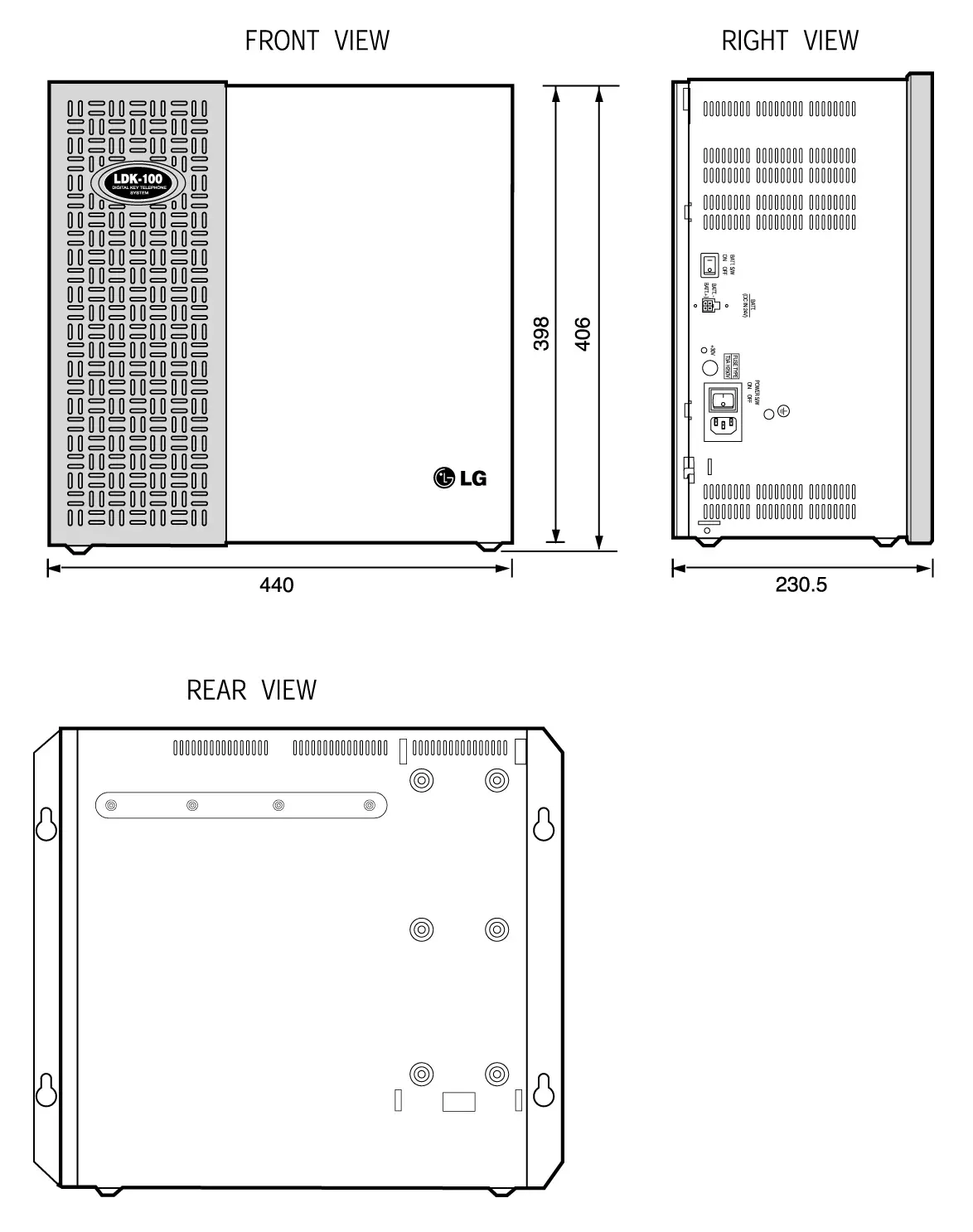
Figure 3.3.1 KSU Exterior
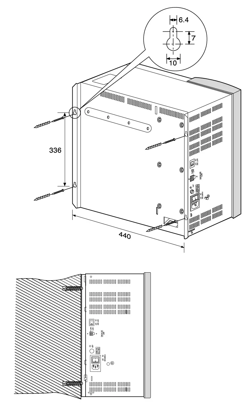
Figure 3.3.2 1st KSU Mounting Holes & Installation Layout
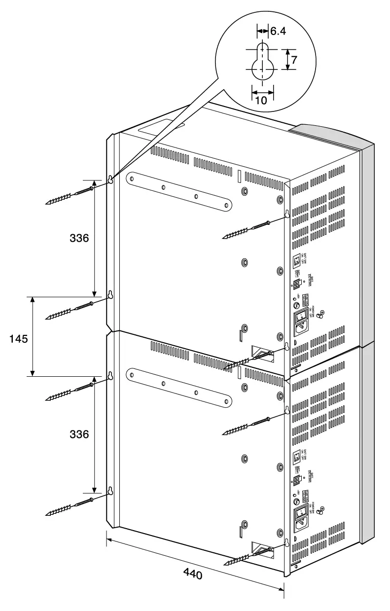
Figure 3.3.3 1st, and 2nd KSU Mounting Holes & Installation Layout 1
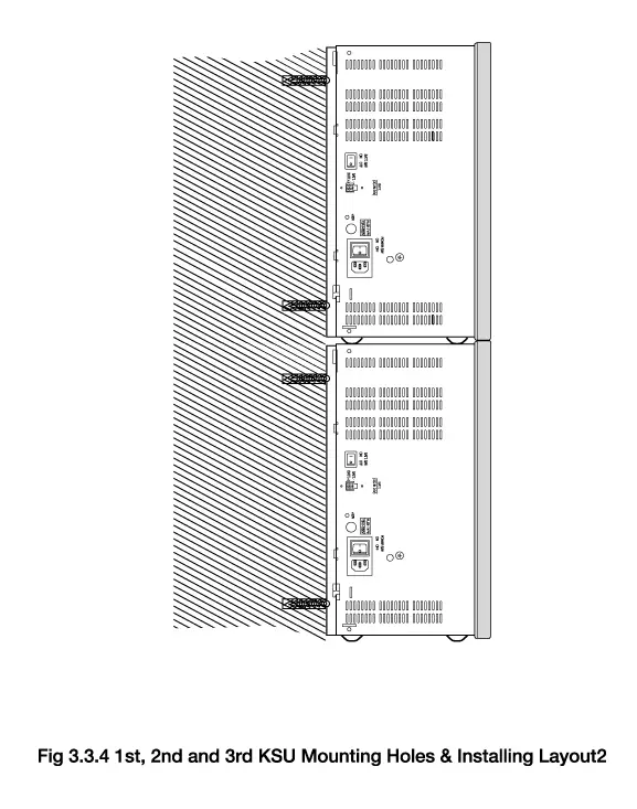
Figure 3.3.4 1st and 2nd KSU Mounting Holes & Installation Layout 2
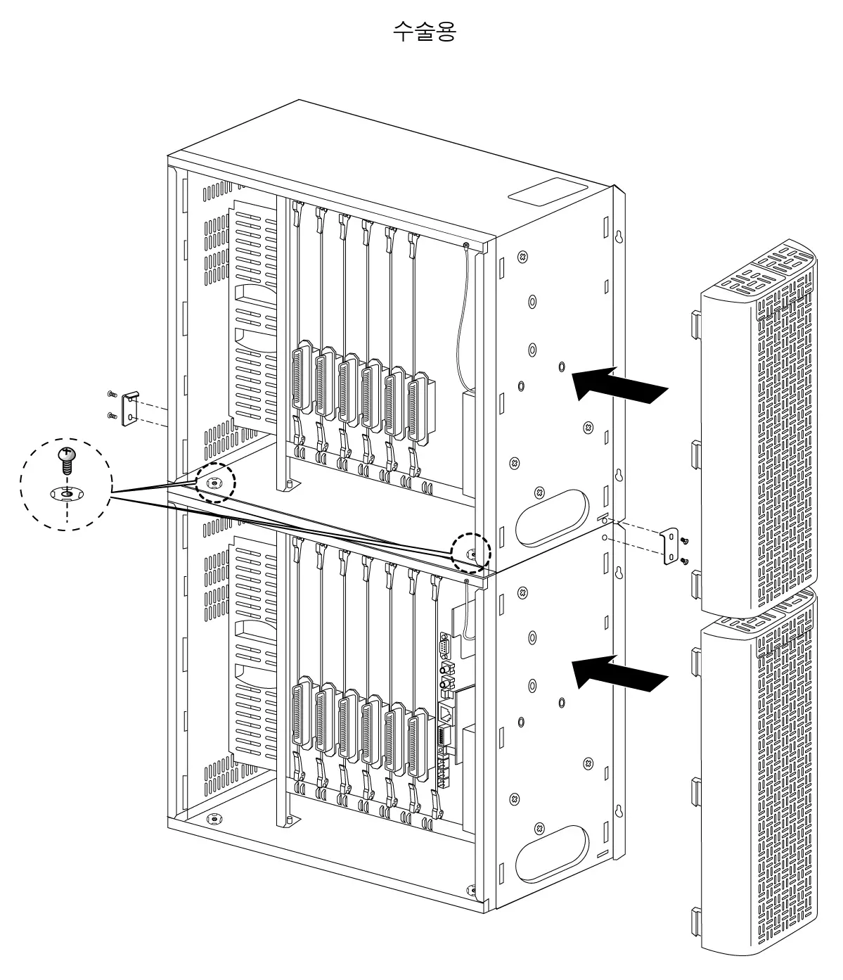
Figure 3.3.5 Connection between 1st KSU and 2nd KSU
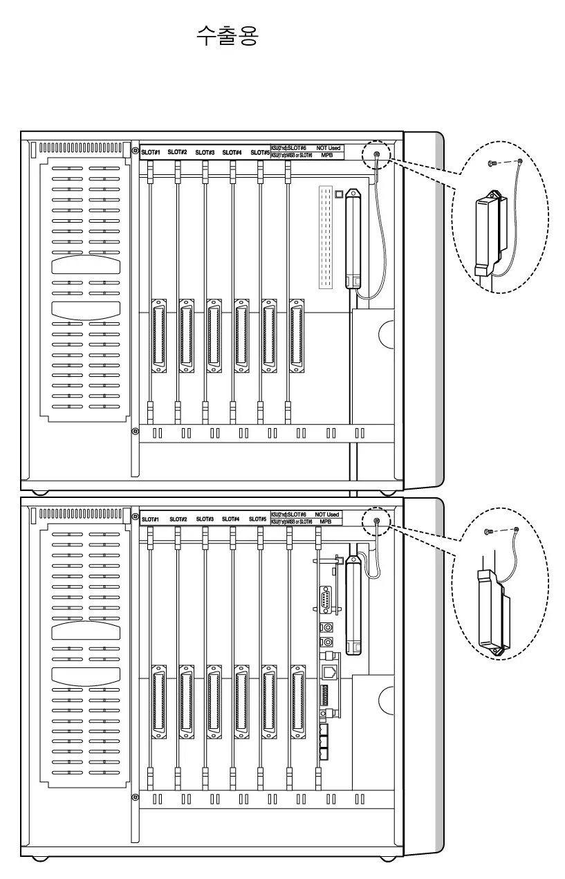
Figure 3.3.6 Connection between 1st KSU and 2nd KSU
RGU Installation
The Ring Generator Unit(RGU6) is needed in the 1st and 2nd KSU if SLIB24, SLIB48, SLIBII, SLIB2E and DSIB are to be installed, to provide Ring voltage and Message Wait Source.
The internal RGU6 is fixed on the right bottom side panel with the two screws provided inside the KSU and is connected to RGU (marking on PCB) connector on the system back-plane of KSU.
See Fig 3.3.7.
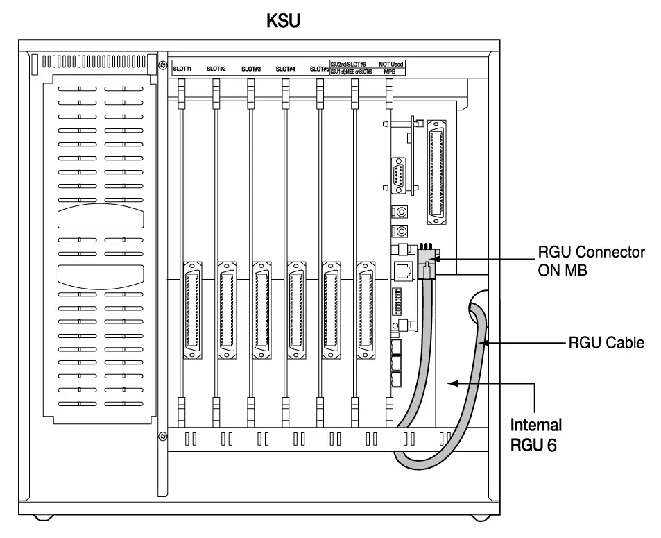
Figure 3.3.7 RGU Installation
A corresponding cable for connecting between external/internal RGU and KSU is provided with RGU in the same package.
PFTU Installation
The PFTU provides the relay contacts for the direct connection of 6 Exchange Lines (CO Lines) to 6 Extension Lines (SLT Lines) in event of a power or processor failure. The PFTU can be optionally installed on the right upper side of every KSU.
2 control wires are connected to the PFTU (marking on PCB) on back-plane of the system regardless of the polarity of control wires. The PFTU connector is provided but control wires should be got locally. The specification of control wires is AWG #22, #24 or #26 regardless of their length.
A RJ21 type connector, which consists of 25 pairs, is connected CO line, LCOB, SLIB and SLT as section 3.5.5 PFTU Wiring.
An earth terminal is provided, and the grounding method of the PFTU is shown in Fig 3.3.9 when the PFTU is installed outside KSU. And there is a test switch on the surface of PFTU; TEST position of the switch is used for testing PFTU function, and NORMAL position of the switch for normal operation.
In case a PFTU can be installed in the inside of KSU. Its position is the upper side of RGU position.
See Fig 3.3.8 for connection earth cable.

Figure 3.3.8 The exterior of PFTU
KSU Grounding
Before connection to the mains supply, the Aria-130 system must have a hard-wired protective earth installed by a qualified person. The protective earth is required for user safety and also to minimise EMC interference.
This is a mandatory requirement to satisfy ACA compliance.
A separate cable should be used between the ground source and the KSU, UL 1015 AWG #18 or larger copper wire is recommended. The wire should be kept as short as possible, it is recommended that the wire be no longer than 1 meter (about 3.28 feet).
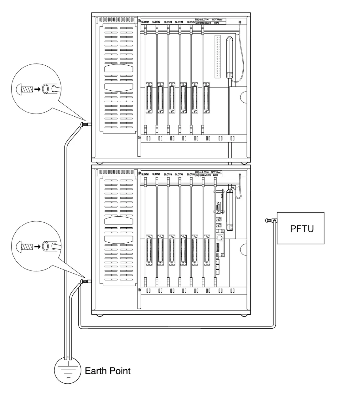
Connecting Wire: 1. UL 1015 AWG#18 or larger than this.
2. Length ≤ 1 meter * The shorter the length of wire is, the better it is.
3. Color : Green / Yellow
Figure 3.3.9 The Connection Method of Earth Cable between KSU, External PFTU
AC Input Selection at PSU
The Power Supply Unit (Fig 3.3.10.a) provides power for the system boards and telephones, converting the AC Voltage input to appropriate DC voltages.
ARIA-130 has a built-in PSU for each cabinet, which is supplied with KSU as basic component.
Fig 3.3.10.a shows connectors and switches from PSU, and Fig 3.3.10.b shows the inside after removing PSU shield cover.
The PSU can operate from either 110 or 220/230 Volts AC according to the position of Input Voltage Selection Connector of the PSU board as shown in Fig 3.3.10.c. Generally the PSU is shipped with this connector set to 220/230V AC position(CN5).
If local AC input is 110 volts, move the connector to the “110/115V” position, CN6. If local AC is 220/230 volts, move the switch to the “220/230V” position, CN5 .
Default setup of the PSU : 220/230VAC(CN5).
The range of main input voltage and the fuse ratings of ARIA-130 PSU according to the position of VOLTAGE SELECTOR switch are as follows;
| Position of Input Voltage Selection Connector | The Range of Mains Input Voltage | Fuse Ratings ARIA-130PSU |
| CN5(220/230V) | 187V AC ~ 164V AC | 4A @ 250V |
| CN6(110V) | 93V AC ~ 132V AC | 8A @ 125V |
Table 3.3.1 Fuse rating of ARIA-130 PSU
PSU capacity is as follows;
Unit: A
| PSU Type | +5V DC | -5V DC | +30V DC | Battery |
| ARIA-130 PSU (127W) | 4A | 0.5A | 3A | 0.5A |
Table 3.3.2 Power Capacity of ARIA-130 PSU
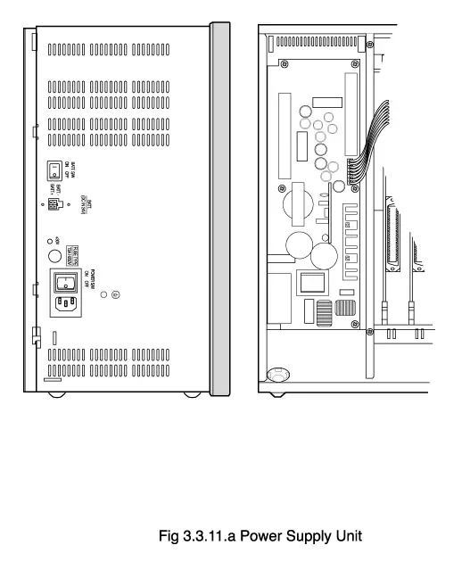
Figure 3.3.10.a Power Supply Unit
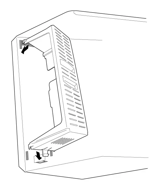
Figure 3.3.10.b PSU Shield Cover
Power
Inlet
○
○
To Frame Ground
CN1
F1
T3.15A H250V
LED1
○
○
○
○
○
○
○
○
L3
C1
L1
L2
C4
C3
Z1
R1
C6
R3
○
○
CN5
220/230V
○
○
CN6
110V
C8
C9
R2
Input Voltage
Selection
Figure 3.3.10.c AC Input Selection
PCB INSTALLATION
PCB Handling And General Installation
No board should not be installed or removed with power applied.
Power must be turned off prior to insertion or removal of the PCB.
The system PCBs contain digital circuitry which, while extremely reliable, can be damaged by exposure to excessive static electricity. When handling PCBs, a grounded wrist strap should be used to protect the boards from static discharges. Also, use common sense when handling the PCBs. For example, do not place a PCB in locations where heavy objects might fall on the PCB and damage components.
To insert a PCB, hold the PCB by the injectors and, with components facing right, align the top and bottom edge of the PCB in the card guides. Slide the card into the system and use the injectors to seat the PCB firmly into the back plane connectors. To remove a PCB, reverse the procedure. Installation method of PCB is shown in Fig 3.4.1.
* Note : Care should be observed when inserting the MPB so that damage does not occur to the DIN connector pins(male pins) on the back plane.
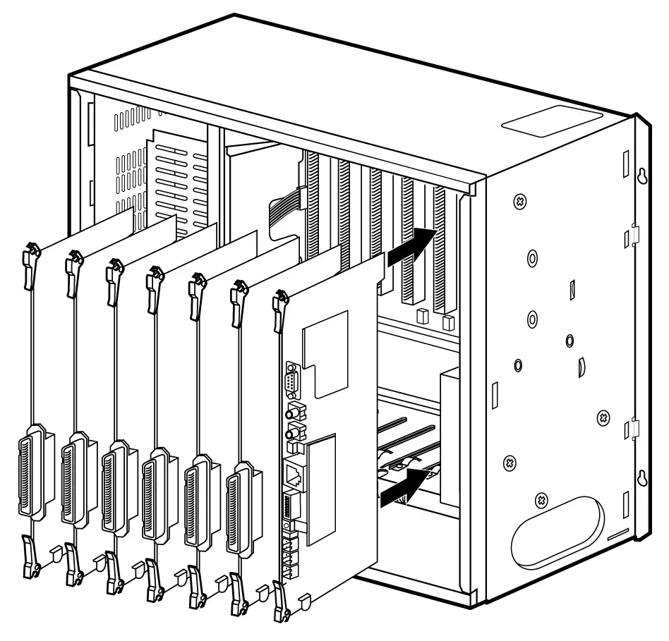
Figure 3.4.1 PCB Installation
MPB Installation
The MPB is installed only in the MPB slot of the 1st KSU. The MPB may be equipped with 6 add-on boards; PMU for software program, a MODU for modem access to the system, and a SDRAM for software downloading and additional features. See Fig 3.4.2.
Lithium Battery
The MPB contains a lithium dry-cell battery to maintain memory and real-time clock functions. The battery is soldered on the MPB, and connected circuitry by on-off DIPswitch. So the switch is set to ON position before the MPB installation.
“ CAUTION: The system will not function properly if battery is incorrectly replaced. Replace only with the same or equivalent type recommended by the manufacturer. Dispose of used batteries
according to the manufacturers instruction.”
RLY1 RLY2
1
2
3
4
5
6
7
8
PMU
CN1
CN2
DBID II
GSXD
CPU
S3C4530A
DMEMU
SMEMU
PLLU
OFF
Serial port
PJ1
Ext. MOH
PJ2
Ext. PAGE
SIU / MODU
ALARM
JTAG
connector
Battery
Switch
ARIA-130 MPB
LANU
Figure 3.4.2 MPB, PMU and option board configuration
Function of LEDs
The 8 LEDs mounted in the MPB provide diagnostic information for states of the board. Table 3.4.1 LEDs on the MPB shows the meaning of various states of LEDs.
| LED No. | Meaning |
| LED1 | Not used |
| LED2 | Timer, Flashing every 100msec |
| LED3 | Dial Processing , Flashing every 100msec |
| LED4 | SLT Ring Processing, Flashing every 200msec |
| LED5 | LCD active updating, Flashing every 300msec |
| LED6 | Call Event Processing |
| LED7 | RS-232C Tasking |
| LED8 | Interrupt Processing |
Table 3.4.1 LEDs on the MPB
Function of SW3
The MPB also has an eight-position DIP switch, SW3. The function of each switch position is as followings;
Default setting: All ON position
| Switch | Function | OFF | ON |
| 1 | Administration Programming Access | Disable | Enable |
| 2 | CTS (Clear to Send) of RS-232C | Enable | Disable |
| 3 | Command/Event Trace (The purpose of testing software) | Enable | Disable |
| 4 | Not used | – | – |
| 5 | SMDI (Simplified Message Desk Control –Voice Mail ) | SMDI ON | SMDI OFF |
| 6 | Not used | – | – |
| 7 | Power up status trace of board | Enable | Disable |
| 8 | Database default on power up | Disable | Enable |
Table 3.4.2 The function of each pole of SW3
Before programming the system, switch 8 should be placed in the on position and power cycled off and on to initialize the system database to default. Once the database has been initialized, switch 8 should be placed in the off position so as to protect the database.
After the lithium batteries(SW1 ON) and Add-on boards installed, insert MPB into the MPB slot of the 1st KSU.
Function of various switches and connectors
| Switch/Connector | Functions | Remark |
| SW1 | Lithium Battery ON/OFF switch | |
| SW2 | CPU Reset | |
| SW3 | Refer to table 3.4.2 | |
| SW5 | JTAG Reset for emulator | Always off |
| CN1 and CN2 | PMU connection | |
| CN3 | JTAG connection | |
| CN4 and CN5 | SMEMU connection | |
| CN6 and CN7 | DMEMU connection | |
| CN9 and CN10 | LANU connection | |
| CN12 | MODU or SIU connection | |
| CN16 and CN17 | PLLU connection | |
| CN18 | 2nd relay contact | |
| CN19 | Alarm detect port | |
| CN20 | 1st relay contact | |
| PJ1 | External Music | Note 1 |
| PJ2 | External paging connection | Note 1 |
Table 3.4.3 Function of various switches and connectors
* Note:
- MPB should be installed only in the MPB slot of the 1st KSU.
- The Dipswitch, SW1 should be turned ON before the MPB installation to protect system data in the case of a power fail.
- The 8th pole (switch 8) of SW3 should be OFF to protect the variety features by Admin programming after the system power up and initialization. See Table 3.4.2.
When the system power is on, the default slots will be automatically redefined from the most left slot if the 8th pole of SW 3 is set to ON position. So It is recommended that a board among DTIB12, DTIB24 and DSIB is installed in the most left slot and a Digital Keyset with display is connected to the first port the board when the first initialization of the system, since only the FIRST STATION of the system can access the system database without PC Administration.
Add-on boards: PMU, MODU, LANU, SIU, SMEMU, DMEMU, PLLU
Note 1 – An ACA approved LIU must be installed to the external paging and MOH port
PMU Installation
The MPB should be equipped with PMU for system operation. Before installing the MPB, install PMU. Refer to Fig 3.4.2.
The PMU should be installed on MPB through the dual line connectors, CN1 and CN2 of MPB, so recommend visual inspection of the connecting state between MPB and PMU after installing it on MPB.
SMEMU Installation
SMEMU board has 2 Mbytes SRAM which is used for database of following features:
– PC Attendant
– CTI
– Networking
The SMEMU should be installed on MPB through the dual line connectors, CN6 and CN7 of MPB.
Note: The DIP switch, SW1 on SMEMU should be turned ON position before installation to protect system database in the case of a power fail.
LANU Installation
LANU board has 10/100 Mbps Ethernet interface for LAN connection, and can be sued for following features :
– Software upgrade via LAN
– Remote diagnostics
– CTI
– PC attendant at LAN network
– Networking
The LANU should be installed on MPB through the dual line connectors, CN9 and CN10 of MPB.
PLLU Installation
PLLU board has the function to synchronize the system clock to network, when using ISDN board and digital trunk(E1, R2DCOB).
PLLU should be installed on MPB through the dual line connectors, CN16 and CN17 of MPB.
Note: When not using PLLU, the pin #7 and #8 of CN17 should be short with a short pin, which is supplied with MPB
DMEMU Installation
DMEMU has 16M bytes EDO-DRAM which is needed for software download via following method :
- LAN Port : LANU
- Serial Port : RS232
- Analog Modem : MODU.
DMEMU should be installed on MPB through the dual line connectors, CN6 and CN7 of MPB.
MODU Installation
The MODU is used for remote access the system for system maintenance, PC based administration function and Software download(with DMEMU).
MODU can be installed on MPB through CN12 of MPB.
Note:
- One of MODU and SIU can be installed on the same connector of MPB selectively, not both.
SIU Installation
The SIU board is used for system maintenance, PC based Admin, SMDR print, SMDI and software download. The system supports up to 2 Serial Interface circuits, 1 circuit on MPB and additional 1 circuits on SIU board.
Followings are the list of the system’s output;
– Administration database
– Off-line SMDR (on-demand)
– On-line SMDR
– Statistical Information
– SMDI (voice mail)
System trace data
Software download
Note:
- SIU board can be installed only on MPB.
- SIU should be fixed on MPB with our plastic supporters provided.
- One of MODU and SIU can be installed on the same connector of MPB selectively, not both.
MISB Installation
The MISB contains 2 MOH inputs, 2 external paging ports and four dry contacts, and an alarm detection.
| Connectors/Switches | Function | Remark |
| CONN1 | Not support | |
| CHAMP1 | RJ21 type female connector(25-pair Amphenol) for External Paging, External MOH, Relay contacts, and Alarm Input | See the clause 3.5.3 |
Table 3.4.4 Function of various connectors on MISB
Note :
- One MISB can be installed only in the slot No. 6 of the 1st KSU.
- In ARIA-130, SIU can not be installed on MISB .
Extension Board Installation
The system can be equipped with any combination of the extension boards; DTIB12, DTIB24, SLIB24, SLIB48, SLIBII, SLIB2E, DSIB, and WTIB. The station interface boards can be installed in any card slots in KSU.
It is recommended to install extension boards, e.g. DTIB from the left most slot (slot No.1). Also, since the first port of SLOT # 1 will be the database access port, it is recommended that a DTIB be installed in this slot and a Digital Keyset with display be connected to this port.
DTIB12/DTIB24 Installation
DTIB12/DTIB24/DSIB can be installed in any universal No 1 ~ 6 of any KSU.
Since the first port of SLOT 1 will be the database access port, it is recommended that a DTIB12, DTIB24 or DSIB be installed in this slot and a digital keyset with display be connected to this port.
Function of LEDs
| LED | Function | Remark |
| LED1 | The status of ports. (ON: in use, OFF: idle) |
Table 3.4.5 LEDs on DTIB12/24
Function of connector
| Connector | Function | Remark |
| CHAMP1 | RJ21 type female connector for terminal connection. |
Table 3.4.6 connector on DTIB12/24
Note:
- The distance between Digital Terminal Interface Board and Digital Terminal: see Table 2.3.5
In ARIA-130 system, LKD-30DS with 2B-module and secondary terminal can be connected to only every even-numbered port (0,2,4,…) of DTIB12/DTIB24/DSIB, then any digital terminal can not be connected to the consecutive odd port(1,3,5,…) in that case. See clause 2.4.12.3 2B-module and clause 2.4.12.4 GDK-PC PHONE in section 2 for more details regarding 2B-module and CTI module.
C
H
A
M
P
1
Figure 3.4.3 DTIB
DTIB12/DTIB24 can be installed in any universal slot No. 1-6 of any KSU.
So It is recommended that a board among DTIB12, DTIB24 and DSIB is installed in the most left slot and a Digital Keyset with display is connected to the first port the board when the first initialization of the system, since the FIRST STATION of the system at first can only access the system database without PC Administration. See clause 3.4.2 MPB Installation.
SLIB24/SLIB48 Installation
SLIB24/SLIB48 can be installed in any universal slot and allows 6 single line analogue devices to be connected. A MSGU/MSGU48 with 6 circuits can be optionally installed on SLIB24/SLIB48 respectively to light a message waiting lamp in the SLT connected to SLIB24/SLIB48, and a DTRU with 2 receivers can be optionally installed on SLIB24/SLIB48 to receive DTMF signals.
Function of LED
| LED | Function | Remark |
| LED1 | The status of ports. (ON: in use, OFF: idle) |
Table 3.4.7 LED on SLIB24/48
Function of various connectors
| Connector | Function | Remark |
| CONN1 and CONN2 | DTRU connection | |
| CONN3 and CONN4 | MSGU and MSGU48 connection | 1) |
| CHAMP1 | RJ21 type connector (female) for terminal connection |
Table 3.4.8 connector on SLIB24/48
Note:
- If you want Message Waiting function on SLIB24 or SLIB48, MSGU or MSGU48 should be installed on SLIB24 or SLIB48 respectively. MSGU can be installed on SLIB24, and MSGU48 can be installed on SLIB48.
- The distance between SLIB and SLT : see Table 2.3.5
- Maximum 2 SLIB48 cards can be installed in a cabinet.
Add-on boards: DTRU, MSGU(on SLIB24), MSGU48(on SLIB48)
D
T
R
U
MSGU
Or
MSGU48
C
H
A
M
P
1
Figure 3.4.4 MSGU/MSGU48 and DTRU Installation
SLIBII Installation
SLIBII can be installed in any universal slot and allows 12 single line analogue devices to be connected. A MSGUII with 12 circuits can be optionally installed on SLIB II to light a message waiting lamp in the SLT, and a DTRU II with 4 receivers can be optionally installed on SLIB II to receive DTMF signals.
Function of LED
| LED | Function | Remark |
| LD1 | The status of ports. (ON: in use, OFF: idle) |
Table 3.4.9 LEDs on SLIBII
Function of various connectors
| Connector | Function | Remark |
| CN2 and CN4 | DTRUII connection | |
| CN3 and CN5 | MSGUII connection | 1) |
| CN1 | RJ21 type connector (female) for terminal connection |
Table 3.4.10 connector on SLIBII
Note:
- If you want Message Waiting function on SLIBII, MSGUII should be installed on SLIBII.
- The distance between SLIBII and SLT: see Table 2.3.5
Add-on boards: DTRU II, MSGU II
CN1
MSGU II
DTRU II
Figure 3.4.5 MSGU II and DTRU II Installation
SLIB2E Installation
SLIB2E can be installed in any universal slot and allows 12 single line analogue devices to be connected. Two MSGU48 can be optionally installed on SLIB2E to light a message waiting lamp in the SLT, and a DTRU4 with 4 receivers can be optionally installed on SLIB2E to receive DTMF signals.
ARIA-130 SLIB2E Iss: Rev:
CN8
●
DTRU4
SERVICE
NORMAL
ON:COUNTRY
OFF:CTR21
●
●
CN6
CN5
CN7
●
MSGU48
MSGU48
SW2
SW1
CN1
CN2
Figure 3.4.6 SLIB2E and MSGU48 configuration
Function of Switch
| SW | Function | Remark |
| SW1 | Mode selection switch ON : Country mode OFF : CTR21 mode | 1), 2) |
| SW2 | Upper Side – Normal Operation(short loop) Lower Side – Service Position(long loop) | 3), 4) |
Table 3.4.11 Switches on SLIB2E
Note:
- Country mode : H/W gain and transmission characteristics depend on Each country Spec.
- CTR21 mode : H/W gain and transmission characteristics depend on CTR21 Specification.
- ARIA-130 does not support the function of normal/service selection.
- SW2 is used for selection of short loop or long loop in special country.
[ special country ( impedance = 600ohm ) : standard, India, Israel, China ]
Function of LED
| LED | Function | Remark |
| LD1 | The status of ports. (ON: in use, OFF: idle) |
Table 3.4.12 LEDs on SLIB2E
Function of various connectors
| Connector | Function | Remark |
| CN1 and CN2 | DTRU4 connection | |
| CN6, CN7 and CN5, CN8 | MSGU48 connection | |
| CN9 | RJ21 type connector (female) for terminal connection |
Table 3.4.13 connector on SLIB2E
Note:
- If you want Message Waiting function on SLIB2E, MSGU48 should be installed on SLIB2E.
- The distance between SLIB2E and SLT : see Table 2.3.5
SLIB2E can be installed in any universal slot No. 1-6 of any KSU
Add-on boards: DTRU4, MSGU48
CN9
MSGU48
DTRU4
MSGU48
Figure 3.4.7 MSGU48 and DTRU4 Installation
DSIB Installation
DSIB can be installed in any universal slot and allows 6 Digital terminals and 6 single line analogue devices to be connected. A MSGU with 6 circuits can be optionally installed on DSIB to light a message waiting lamp in the SLT connected to DSIB, and a DTRU with 2 DTMF receivers can be optionally installed on DSIB to receive DTMF signals using a system resource.
Function of LED
| LED | Function | Remark |
| LED1 | The status of ports. (ON: in use, OFF: idle) |
Table 3.4.14 LEDs on DSIB
Function of various connectors
| Connector | Function | Remark |
| CN1 and CN2 | DTRU connection | |
| CN3 and CN4 | MSGU connection | 1) |
| CN5 | RJ21 type connector (female) for terminal connection |
Table 3.4.15 connector on DSIB
Note:
- If you want Message Waiting function with SLT, MSGU should be installed on DSIB.
- The distance between DSIB and Digital terminal/SLT: see Table 2.3.5
DSIB can be installed in any universal slot No. 1-6 of any KSU.
Add-on boards: DTRU, MSGU
CN5
MSGU
DTRU
Figure 3.4.8 MSGU and DTRU Installation
DTRU/DTRU II/DTRU 4 Installation
A DTRU contains 2 DTMF receiver circuits and a DTRU II/DTRU 4 has 4 DTMF receiver circuits. Each receiver of DTRU/DTRU II/DTRU 4 is time-shared under the control of the system software, as a system resource regardless its position.
| BOARD | The position of Installation | The quantity of receivers | Marking on PCB |
| DTRU | SLIB24, SLIB48, DSIB, LCOB | 2 DTMF receivers | DTRU of GDK-34 |
| DTRU II | SLIB II | 4 DTMF receivers | GDK-100 DTRU II |
| DTRU 4 | SLIB II, SLIB2E | 4 DTMF receivers | ARIA-130 DTRU 4 |
Table 3.4.16 DTRU
The System is capable of supporting DTMF receivers up to 46.
At least a DTRU or DTRU II should be installed to receive DTMF signals.
Take a cautious attitude in installing DTRU on the boards because DTRU contains the connectors without the connection guide, otherwise DTRU may be damaged by wrong connection.
MSGU/MSGU48/MSGUII Installation
A message waiting unit can be optionally installed on a SLT interface board to light a message waiting lamp in the SLT connected. There are 3 kinds of message waiting units as followings according to the line voltage.
| BOARD | The position of Installation | The quantity of circuits | The line voltage |
| MSGU | SLIB24, DSIB | 6 circuits | +24V DC |
| MSGU48 | SLIB48, SLIB2E | 6 circuits | -48V DC, -28V DC(SLIB2E) |
| MSGU II | SLIB II | 12 circuits | -28V DC |
Table 3.4.17 MSGU
- Signal voltage: 90~100V DC
Analog CO Line Board Installation
There are several types of analog CO line boards available.
Every CO line board contains several types of connectors for the line connection on the front edge of the boards themselves.
Maximum 40 CO lines can be installed in ARIA-130 system.
LCOB Installation
LCOB provides 4 Loop Start CO line interfaces. The board can be optionally equipped with Call Metering Unit (CMU) boards to monitor call duration and a Call Progress Tone Unit (CPTU) daughter board to detect call progress signals. A CMU must be provided for each Loop Start CO Line which requires call metering. In addition, the appropriate type of CMU must be employed.
If required, install the CMUs and CPTU on the CO interface board as shown in Fig 3.4.10 and insert the boards in the selected card slot.
Function of LED
| LED | Function | Remark |
| LED1 | The status of line 1, ON: in use, Green | |
| LED2 | The status of line 2, ON: in use, Green | |
| LED3 | The status of line 3, ON: in use, Green | |
| LED4 | The status of line 4, ON: in use, Green |
Table 3.4.18 LED on LCOB
Function of various connectors
| Connector | Function | Remark |
| CN1 and CN2 | DTRU connection | |
| CN3 and CN4 | CPTU/A or CPTU/B connection | |
| CN100 and CN104 | The connectors for a CMU on line 1 | See Note |
| CN101 and CN105 | The connectors for a CMU on line 2 | See Note |
| CN102 and CN106 | The connectors for a CMU on line 3 | See Note |
| CN103 and CN107 | The connectors for a CMU on line 4 | See Note |
| CN108 | RJ21 type male connector for CO line connection. |
Table 3.4.19 connector on LCOB
- Note:
- The pin #6 and #7 of CN104, CN105, CN106 and/or CN107 should be shorted by shorting traps (short pin) when CMU12(12 KHz meter pulse) including CMU12PR or CMU16(16 KHz meter pulse) is not installed on the interface circuit(s). Otherwise the receiving voice path of the related line will be open.
- The 0 ohm resistors are usually mounted on R168-R171 of LCOB for the countries using only CMU PR(Polarity Reversal) and/or 50L(50 Hz longitudinal). If these CMUPR, CMU50L or CMU50PR are not installed on any CO interface circuit neither R168-R171 are mounted on LCOB, the pin #6 and #7 of CN104, CN105, CN106 and/or CN107 should be also shorted by shorting traps (short pin) on the related interface circuit.
- CN104/R168 are on the 1st interface circuit, CN105/R169 on the 2nd interface circuit, CN106/R170 on the 3rd interface circuit and CN107/R171 on 4th interface circuit.
LCOB can be installed in the universal slot No. 1-6 of any KSU.
Add-on boards: DTRU, CPTU/A, CPTU/B, CMU
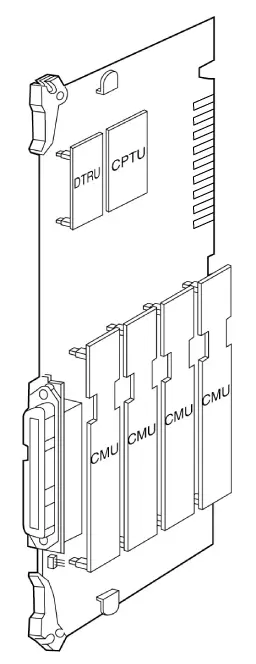
Figure 3.4.9 CMU & CPTU & DTRU Installation
LCOB8 Installation
LCOB8 provides 8 Loop Start CO line interfaces. The board can be optionally equipped with two Call Metering Unit (CMU4) boards to monitor call charge and a Call Progress Tone Unit (CPTU4) board to detect call progress signals and a DTMF Receiver Unit (DTRU4) to detect DTMF.
A CMU4 supports 4 channels call metering function. And the appropriate type of CMU4 should be installed on the line according to the national specification.
If required, install the DTRU4, CMU4s and CPTU4 on the CO interface board as shown in Fig 3.4.12.
ARIA-130 LCOB8 Iss: Rev:
CN2
●
CN9
DTRU4
SERVICE
NORMAL
………
CPTU4
……
CN8
ON:COUNTRY
OFF:CTR21
●
●
CMU4
CMU4
CN4
CN6
CN5
CN7
SW2
SW1
CN3
Figure 3.4.10 LCOB8, CMU4, CPTU4 and DTRU4 configuration
Function of Switch
| SW | Function | Remark |
| SW1 | Mode selection switch ON : Country mode OFF : CTR21 mode | 1), 2) |
| SW2 | Upper Side – Normal Operation(short loop) Lower Side – Service Position(long loop) | 3), 4) |
Table 3.4.20 Switches on LCOB8
- Note:
- Country mode : H/W gain and transmission characteristics depend on Each country Spec.
- CTR21 mode : H/W gain and transmission characteristics depend on CTR21 Specification.
- ARIA-130 does not support the function of normal/service selection.
- SW2 is used for selection of short loop or long loop in special country.
[ special country (impedance = 600ohm ) : Standard, India, Israel, China ]
Function of LED
| LED | Function | Remark |
| LED1 | The status of line 1, ON: in use, Green | |
| LED2 | The status of line 2, ON: in use, Green | |
| LED3 | The status of line 3, ON: in use, Green | |
| LED4 | The status of line 4, ON: in use, Green | |
| LED5 | The status of line 5, ON: in use, Green | |
| LED6 | The status of line 6, ON: in use, Green | |
| LED7 | The status of line 7, ON: in use, Green | |
| LED8 | The status of line 8, ON: in use, Green |
Table 3.4.21 LED on LCOB8
Function of various connectors
| Connector | Function | Remark |
| CN2 and CN3 | DTRU4 connection | |
| CN8 and CN9 | CPTU4 connection | |
| CN4 and CN5 | The connectors for a CMU4 on line 1~4 | |
| CN6 and CN7 | The connectors for a CMU4 on line 5~8 | |
| CN10 | Connection between GND and Tel Ground(TEGND) for 50Hz longitudinal meter pulse. | 1) |
| CN1 | RJ21 type male connector for CO line connection and TEGND. |
Table 3.4.22 Connector on LCOB8
- Note:
- The pin #2 and #3 of CN10 should be short by shorting traps (short pin) when 50Hz longitudinal meter pulse is used for call charge.
LCOB8 can be installed in the universal slot No. 1-6 of any KSU.
Add-on boards: DTRU4, CPTU4, CMU4_50PR / CMU4_12PR / CMU4_16
DTRU4
CPTU4
CMU4
CMU4
Figure 3.4.11 CMU4 & CPTU4 & DTRU4 Installation
EMIB Installation
The EMIB provides 4 analog E&M interfaces. It can only support 4 wire E&M signalling, (not 2 wire).
It is designed to comply with the Australian specification.
Function of LED
| LED | Function | Remark |
| LED1 | The status of line 1, ON: in use | |
| LED2 | The status of line 2, ON: in use | |
| LED3 | The status of line 3, ON: in use | |
| LED4 | The status of line 4, ON: in use |
Table 3.4.23 LED on EMIB
Function of various connectors
| Connector | Function | Remark |
| CN1 and CN2 | DTRU connection | |
| CN3 | The connector with screws for line 1 | |
| CN4 | The connector with screws for line 2 | |
| CN5 | The connector with screws for line 3 | |
| CN6 | The connector with screws for line 4 |
Table 3.4.24 Connector on EMIB
2 wire/4 wire selection
This board can support 2 wire and 4 wire E&M depending on the connection of the short pin assembled on the CN7~CN10. When EMIB4W is assembled in the factory, the short pin is set to 4 wire connection. Refer to the following Figure 3.4.14 for the detail connection method.
NOTE: this does not apply to the Australian board, which only supports 4 Wire working.
3
2
1
3
2
1
(Factory setting)
(The connection for 2 wire E&M) (The connection for 4 wire E&M)
The short pin connection diagram of CN7~CN10
EMIB can be installed in the universal slot No. 1-6 of any KSU.
Analog CO line boards are limited by maximum 40 analog lines in a system.
When installing E&M line, It is important to check the type of the opposite line and jumper position.
Add-on board: DTRU
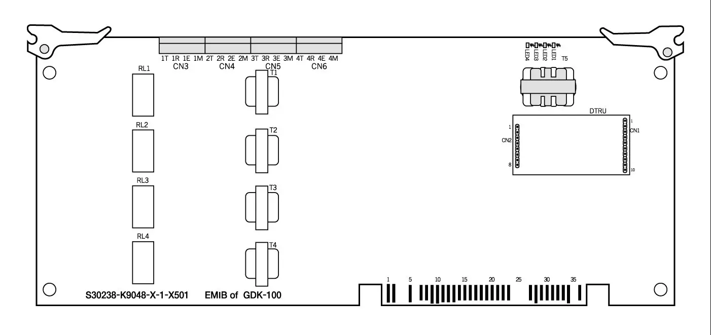
Figure 3.4.12 Board Layout and DTRU installation
VOIB Installation
The VOIB/VOIU can be installed in ARIA-130.
Its main job is to provide the Ethernet interface for S/W applications and VoIP features with optional VoIP daughters.
The VOIB has the capacity for maximum four(4) VOIUs, and each VOIU provides two(2) VoIP channels.
Ethernet Status
T1
CN4
CN5
CN7
CN1
CN3
Ch. Status LED
LD1 ……. LD8
SW4
CN11
SW1
1 ………. 8
SW2
●
●
CN9
VoIP
Card 1
VoIP
Card 2
VoIP
Card 3
VoIP
Card 4
●
●
●
●
●
●
.
.
.
.
.
●
●
CN2
LD14…..LD9
CN6
CN8
(Location : CN1-CN2, CN3-CN4, CN5 – CN6, CN7-CN8)
CN
■■■■■■■■■■■
■■■■■■■■■■■
■■■■■■■■■■■
■■■■■■■■■■■
CN2
VoIP
Daughter
Board
Figure 3.4.14 VOIB and VOIU installation
Function of various switches and connectors
| Switch / Connector | Functions | Remark |
| SW1 | Hardware Reset Switch for CPU (MPC860) | |
| SW2 | To be determined | |
| SW4 | OOS(Out Of Switch) Upper Side – Normal Operation Lower Side – Service Position | |
| CN1 and CN2 | VoIP Board #1 Connection | |
| CN3 and CN4 | VoIP Board #2 Connection | |
| CN5 and CN6 | VoIP Board #3 Connection | |
| CN7 and CN8 | VoIP Board #4 Connection | |
| CN9 | Serial Interface(RS-232C) Connection | |
| CN11 | BDM(Background Debug Mode) Connection | |
| Ethernet Connector T1 | Network(RJ-45) Cable Connection |
Table 3.4.27 Switch & Connector on VOIB
Function of LEDs
| LED | Functions | Remark |
| LD1 ~ LD8 | Channel Status LED(ON : Busy, OFF : Idle) | |
| LD9 | Speed Status LED(ON : 100Mbps, OFF : 10Mbps) | |
| LD10 | Receive Status LED(ON : Receive, OFF : Idle) | |
| LD11 | Transmit Status LED(ON : Transmit, OFF : Idle) | |
| LD12 | Link Status LED(ON : Link OK, OFF : No Link) | |
| LD13 | Collision Status LED(ON : Collision, OFF : Normal Operation) | |
| LED LD14 | Full-Duplex Status LED(ON : Half-Duplex, OFF : Full-Duplex) |
Table 3.4.28 LED on VOIB
Note :
- VOIB can be installed in the universal slot No. 1-6 except slot No. 6 of the 1’st KSU.
- The basic LAN board has the capacity for maximum four(4) VOIU, and each VOIU provides
two(2) VoIP channels.
- Maximum 2 VOIB cards can be installed in ARIA-130 system.
Add-on board : VOIU 1 – VOIU 4
VOIU Installation
VOIU consists of One(1) DSP, One(1) data memory and One(1) DC/DC converter.
VOIU is used to voice compression and de-compression.
The AC48302C-C Voice over Packet Network Processor AC48302C-C VoPNP is a state-of-the-art system on a single chip.
It provides configurable, low-bit-rate voice compression and fax relay functions for up to Two(2) independent PCM voice and fax channels.
ISDN Board Installation
There are 6 kinds of ISDN boards such as ARIA-130 BRIB, ARIA-130 BRIU, ARIA-130 PRIB, GDK-100 BRIB, GDK-100 PRIB and GDK-100 STIB, which can be used with ARIA-130. Each ISDN board contains RJ45 type jack on boards themselves.
| BOARD | CAPACITY | DAUGHTER BOARD | REMARK |
| ARIA-130 BRIB | 2 BRI(4B) | BRIU | Without CPU |
| ARIA-130 BRIU | 2 BRI(4B) | – | ARIA-130 BRIB option board |
| ARIA-130 PRIB | 1 PRI(30B) | – | Without CPU, TE mode only |
| GDK-100 BRIB | 4 BRI(8B) | – | With CPU |
| GDK-100 STIB | 4 BRI(8B) | – | With CPU |
| GDK-100 PRIB | 1 PRI(30B) | – | With CPU, TE/NT mode |
Table 3.4.29 ISDN card for ARIA-130
ARIA-130 ISDN BRIB (Basic Rate T Interface) Installation
The BRIB card provides 2 interface circuits of BRI (Basic Rate Interface) format digital CO interface.
If more than one ISDN board is required, some special cable should be used for clock signal control. CN1(out) and CN2(in) are used to control the clock signal when multi-ISDN boards are installed. Refer to [Clock Control Cable Wiring] of section 3.5.7.5.
Function of LED
| LED | Function | Status | Remark |
| LED1 | The status of Line 1 | Red: Error, Green: In-use, OFF: Idle | |
| LED2 | The status of Line 2 | Red: Error, Green: In-use, OFF: Idle |
Table 3.4.30 LED on BRIB
Function of SW1; default -all OFF while delivering the board
| Pole | Function | ON | OFF | Remark |
| 1 | Loop Back | Enable | Disable | |
| 2 | Reserved | – | – | – |
| 3 | Reserved | – | – | – |
| 4 | Reserved | – | – | – |
Table 3.4.31 Switch on BRIB
The line connector and terminating resistors
| Line No | RJ45 type jack | Terminating Resistors | ||
| Switch | All ON | All OFF | ||
| Line 1 | MJ1 | SW3 | terminating | open |
| Line 2 | MJ2 | SW4 | terminating | open |
Table 3.4.32 Line connector on BRIB
- Note :
- Two poles of SW4 and SW5 should be set to the ON position to terminate two terminating resistors on a line. (default ON)
- BRIB can be installed in the universal slot No 1 ~ 6 of any KSU
- Add-on board : BRIU
CN2(IN)
SW1
1 2 3 4
LD2
LD1
CN1(OUT)
SW2
RJ45
CON5
U10
U11
RJ45
CON6
SW4
ON
2 1
SW3
ON
2 1
BRIU
CN5
CN6
Figure 3.4.15 BRIB Layout
ARIA-130 ISDN BRIU (Basic Rate T Interface) Installation
The BRIU card provides 2 additional interface circuits of BRI (Basic Rate Interface) format digital CO interface for ARIA-130 BRIB.
Function of LED
The BRIU card provides 2 additional interface circuits of BRI (Basic Rate Interface) format digital CO interface for ARIA-130 BRIB.
Function of LED
| LED | Function | Status | Remark |
| LED1 | The status of Line 3 | Red: Error, Green: In-use, OFF: Idle | |
| LED2 | The status of Line 4 | Red: Error, Green: In-use, OFF: Idle |
Table 3.4.33 LED on BRIU
The line connector and terminating resistors
| Line No | RJ45 type jack | Terminating Resistors | ||
| Switch | All ON | All OFF | ||
| Line 3 | MJ1 | SW1 | terminating | open |
| Line 4 | MJ2 | SW2 | terminating | open |
Table 3.4.34 Line connector on BRIU
- Note :
Two poles of SW1 and SW2 should be set to the ON position to terminate two terminating resistors on a line. (default ON)
ARIA-130 ISDN PRIB (Primary Rate T Interface) Installation
The PRIB card provides one interface circuit of PRI (Primary Rate Interface) format digital CO interface.
If more than one ISDN board is required, some special cables should be used for clock signal control. CON6 and CON7 are used to control the clock signal when multi-ISDN boards are installed. Refer to [Clock Control Cable Wiring] of section 3.5.7.5.
Function of LED
| LED | Function | Status | Remark on PCB | |
| ON | OFF | |||
| LED1 | Loss Of Signal from the Line | LOS | Normal | LOS |
| LED2 | AIS | Alarm error | Normal | AIS |
| LED3 | Multi-frame Error | Error | Normal | MF |
| LED4 | Remote Alarm Error | Error | Normal | RAI |
| LED5 | CRC Error | Error | Normal | CRC |
| LED6 | The status of the line | In use | All channel idle | IN USE |
Table 3.4.35 LED on PRIB
- Note:
- All LEDs will be the status of OFF when normal operation.
- When PRI line is plugged out, LED 1and 3 will be ON.
Function of SW1: default – all OFF while delivering the board
| Pole | Function | ON | OFF | Remark |
| 1 | Loop back | Enable | Disable | Note 1 |
| 2 | Not used | – | – | |
| 3 | Not used | – | – | |
| 4 | Not used | – | – |
Table 3.4.36 Switch on PRIB
- Note:
- This pole is for the purpose of testing PRIB.
- PRIB can be installed in the universal No 1 ~ 6 of any KSU.
Check Points
Figure 3.4.16 ARIA-130 PRIB Layout
ARIA-130 PRIB
RJ45
CON8
CON2(IN)
SW1
U4
1 2 3 4
1 4
LED1
LED2
LED3
LED4
LED5
LED6
CON1(OUT)
U1
U2
U3
- PRIB can be installed in the universal slot No. 1-6 of any KSU.
- For QSIG operation, check the mode setting method and the contact assignments of RJ45 type connector according to the mode of line , TE or NT. See the clause 3.5.7.
- The clock control cable should be connected to the proper position when multi-ISDN cards are installed in a system. See section 3.5.7.5.
GDK-100 ISDN BRIB (Basic Rate T Interface) Installation
The BRIB card provides 4 interface circuits of BRI (Basic Rate Interface) format digital CO interface.
If more than one ISDN board is required, some special cable should be used for clock signal control. CON3 and CON4 are used to control the clock signal when multi-ISDN boards are installed. Refer to [Clock Control Cable Wiring] of section 3.5.7.5.
Function of LED
| LED | Function | Status | Remark |
| LED1 | The status of Line 1 | Red: Error, Green: In-use, OFF: Idle | |
| LED2 | The status of Line 2 | Red: Error, Green: In-use, OFF: Idle | |
| LED3 | The status of Line 3 | Red: Error, Green: In-use, OFF: Idle | |
| LED4 | The status of Line 4 | Red: Error, Green: In-use, OFF: Idle |
Table 3.4.37 LED on BRIB
Function of SW1; default -all OFF while delivering the board
| Pole | Function | ON | OFF | Remark |
| 1 | Not used | – | – | |
| 2 | TEI | Fixed TEI | Automatic TEI | Note 1, 2 |
| 3 | Layer 2 trace | Enable | Disable | Note 3 |
| 4 | Layer 3 trace | Enable | Disable | Note 3 |
Table 3.4.38 switch on BRIB
- Note:
- The function of the 2nd pole has been implemented in firmware version 3.1 or later.
- This is set to OFF position as default, therefore it is important to note that the 2nd pole is set to the proper position after checking the type of TEI in your country.
- These two poles are for the purpose of developing and maintaining BRIB.
Function of various connectors
| Connector | Function | Remark |
| CON1 | Serial interface connector | Note1 |
| CON2 | The purpose of development. It is not fixed on the products. | |
| CON3 | Clock control IN | Note 2 |
| CON4 | Clock control OUT | Note 2 |
Table 3.4.39 connector on BRIB
- Note:
- CON1: Trace for the purpose of development and maintenance.
The external module for RS-232C serial interface should be required for trace.
See GDK-TRC1 in section 2.
- CON3, CON4: They are used to control the reference clock signal when multi-ISDN boards are installed.
The line connector and terminating resistors
| Line No | RJ45 type jack | Terminating Resistors | ||
| Switch | All ON | All OFF | ||
| Line 1 | CON8 | SW5 | terminating | open |
| Line 2 | CON7 | SW4 | terminating | open |
| Line 3 | CON6 | SW3 | terminating | open |
| Line 4 | CON5 | SW2 | terminating | open |
Table 3.4.40 Line connector on BRIB
- Note
- Two poles of SW2, SW3, SW4 and SW5 should be set to the ON position to terminate two terminating resistors on a line. (default ON)
- Terminating resistors and selectable switches are introduced only on PCB issue 3 or later, but not on PCB issue 1 and 2. So if you use BRIB issue 1 and 2, the external terminating resistors are required. For the external termination, you can get the terminating unit locally or use GDK-162/100 TERM, which is the terminating unit with 4 P-to-P connections provided by LGE.
RJ45
CON5
CON3(IN)
SW1
1 2 3 4
GDK-100 BRIB
LED1
LED2
LED3
LED4
CON4(OUT)
CON1
U11
(ROM1)
U10
(ROM2)
RJ45
CON6
RJ45
CON7
CON2
RJ45
CON8
1 2 3 4
SW5
1 2
ON
OFF
SW4
1 2
ON
OFF
SW3
1 2
ON
OFF
SW2
1 2
ON
OFF
Figure 3.4.17 BRIB Layout
Check Points
- BRIB can be installed in the universal slot No. 1-6 of any KSU.
- The 2nd pole of SW1 should be set to the proper position according to the type of TEI.
- The RX and TX pairs of line should be correctly connected to the TX and RX pairs of NT1.
- The clock control cable should be connected to the proper position when multi-ISDN cards are installed in a system. See section 3.5.7.5.
- Terminating resistors on the line.
ISDN STIB ( Basic Rate S/T Interface) Installation
STIB card provides 4 interface circuits of Basic Rate format digital CO and/or Extension interface. If more than one ISDN board is required, some special cable should be used for clock signal control. CON3 and CON4 are used to control the clock signal when multi-ISDN boards are installed. Refer to [Clock Control Cable Wiring] of section 3.5.7.5.
Function of LED
| Line No | Function | Status | Remark |
| LED1 | The status of Line 1 | Red: Error, Green: In-use, OFF: Idle | |
| LED2 | The status of Line 2 | Red: Error, Green: In-use, OFF: Idle | |
| LED3 | The status of Line 3 | Red: Error, Green: In-use, OFF: Idle | |
| LED4 | The status of Line 4 | Red: Error, Green: In-use, OFF: Idle |
Table 3.4.41 LED on STIB
Function of SW1: default – all OFF while delivering the board
| Pole | Function | ON | OFF | Remark |
| 1 | Not used | – | – | |
| 2 | TEI | Fixed TEI | Automatic TEI | Note 1, 2 |
| 3 | Layer 2 trace | Enable | Disable | Note 3 |
| 4 | Layer 3 trace | Enable | Disable | Note 3 |
Table 3.4.42 switch on STIB
- Note:
- The function of 2nd pole has been implemented in firmware version 3.1 or later.
- This is set to OFF position as default, therefore it is important to note that 2nd pole is set to the proper position after checking the type of TEI in your country.
- These two poles are for the purpose of developing and maintaining STIB.
Function of various connectors
| Connector | Function | Remark |
| CON1 | Serial interface connector | Note1 |
| CON2 | The purpose of development. It is not fixed on the products. | |
| CON3 | Clock control IN | Note 2 |
| CON4 | Clock control OUT | Note 2 |
Table 3.4.43 connector on STIB
- Note
- CON1: Trace for the purpose of development and maintenance.
The external module for RS-232C serial interface should be required for trace.
See GDK-TRC1 in section 2.4.15.
- CON3, CON4: They are used to control the reference clock signal when multi-ISDN boards are installed. See [Clock Control Cable Wiring] on section 3.5.7.5.
The line connector and termination switches
| Line No | RJ45 type Jack | S/T selection | Terminating Resistors | ||||
| Switch | all to “T “ | All to “S” | Switch | all to ON | all to OFF | ||
| Line 1 | CON8 | SW4 | T | S | SW9 | terminating | open |
| Line 2 | CON7 | SW3 | T | S | SW8 | terminating | open |
| Line 3 | CON6 | SW2 | T | S | SW7 | terminating | open |
| Line 4 | CON5 | SW5 | T | S | SW6 | terminating | open |
Table 3.4.44 Line connector on STIB
- Note:
- The setting method of S/T selection switches: default -all T position while delivering the board.
- Each line interface can be used for T interface or S interface with different operation interface. If necessary, the S/T selection switches of SW2, SW3, SW4 and/or SW5 can be respectively set to the T or S position by using shorting traps (short pins) supplied on the boards.
- Two poles of SW6, SW7, SW8 and/or SW9 should set to the ON position to terminate two terminating resistors on a line. (default ON)
- Terminating resistors and selectable switches are introduced only on PCB issue 2 or later, but not on PCB issue 1. So if you use STIB issue 1, the external terminating resistors are required. For the external termination, you can get the terminating unit locally or use GDK-162/100 TERM, which is the terminating unit with 4 P-to-P connection provided by LG.
Power does not feeding
Power feeding
POWER
T
S
SW2/SW3/SW4/SW5
Shorting trap
(Short pin)
Figure 3.4.18 Configuration of S/T selection connectors
- Note:
- Each line can be selected to T or S interface according to the needs.
- After setting all lines respectively, the slot(s) of STIB must be assigned as CO slot(s) and STA slot(s) together in Admin field 02 for the proper operation of STIB. See the clause 4.2 and the Programming Manual.
Check Points
- STIB can be installed in the universal slot No. 1-6 of any KSU.
- Each interface should be set to the correct type, T or S with S/T selection connectors, according to the needs of user. And the RX and TX pairs of line should be correctly connected to the TX and RX pairs of NT1 or TE according to the interface type of each line.
- Terminating resistors on the line.
- The 2nd pole of SW1 should be set to the proper position according to the type of TEI.
- The clock control cable should be connected to the proper position when multi-ISDN cards are installed in a system. See section 3.5.7.5.
RJ45
CON5
CON3(IN)
SW1
1 2 3 4
GDK-100 STIB
LED1
LED2
LED3
LED4
CON4(OUT)
CON1
U10
(ROM2)
U11
(ROM1)
RJ45
CON6
RJ45
CON7
CON2
RJ45
CON8
1 2 3 4
SW9
1 2
ON
OFF
SW8
1 2
ON
OFF
SW7
1 2
ON
OFF
SW6
1 2
ON
OFF
CON13
T
S
SW4
T
S
SW3
T
S
SW2
T
S
SW5
Figure 3.4.19 STIB Layout
GDK-100 ISDN PRIB (Primary Rate T Interface) Installation
The PRIB card provides one interface circuit of PRI (Primary Rate Interface) format digital CO interface.
If more than one ISDN board is required, some special cables should be used for clock signal control. CON6 and CON7 are used to control the clock signal when multi-ISDN boards are installed. Refer to [Clock Control Cable Wiring] of section 3.5.7.5.
Function of LED
| LED | Function | Status | Remark | |
| ON | OFF | |||
| LED1 | PLL Synchronization | Sync. Error | Normal | |
| LED2 | Loss Of Signal from the Line | LOS | Normal | |
| LED3 | AIS | Alarm error | Normal | |
| LED4 | Frame Alignment Error | Error | Normal | |
| LED5 | Multi-frame Error | Error | Normal | |
| LED6 | Remote Alarm Error | Error | Normal | |
| LED7 | CRC Error | Error | Normal | |
| LED8 | The status of the line | In use | All channel idle | |
Table 3.4.45 LED on PRIB
- Note:
- All LEDs will be the status of OFF when normal operation.
- When PRI line is plugged out, LED 2, 4 and 5 will be ON.
Function of SW1: default – all OFF while delivering the board
| Pole | Function | ON | OFF | Remark |
| 1 | CRC | Disable | Enable | |
| 2 | Loop back | Enable | Disable | Note 1 |
| 3 | Not used | – | – | |
| 4 | Trace | Enable | Disable | Note 2 |
Table 3.4.46 Switch on PRIB
- Note:
- This pole is for the purpose of testing PRIB.
- This pole is for the purpose of developing and maintaining PRIB.
Function of various connectors
| Connector/Switch | Function | Remark |
| CON1 | Serial interface connector( 4pin) | Note 1 |
| CON2 | The purpose of the software development. | |
| CON3 | NT/TE mode selection for QSIG. ( Default: open – TE) | Note 2 |
| CON5 | Serial interface connector(9-pin RS232C, male) | Note 1 |
| CON6 | Clock control IN | Note 3 |
| CON7 | Clock control OUT | Note 3 |
| CON8 | RJ45 type jack for PRI Line connection | Clause 3.5 |
Table 3.4.47 Connector on PRIB
- Note:
- Access to the board for the purpose of development and maintenance.
Board issue 2 or earlier version:
CON5 is RS-232C, 9 pin male to access the board for the purpose of development and maintenance. This connector can be directly connected with PC for trace (PRIB issue 2 or earlier version).
Board issue 2A or later version:
CON5 and application circuits on PRIB are removed on PRIB issue 2A to unify the method of tracing peripheral cards such as PRIB, BRIB, STIB and WTIB in all LDK systems.
CON1 is mounted to access the board for the purpose of development and maintenance. The external module(GDK-TRC1) for RS-232C serial interface should be required to access the board through this connector.
See GDK-TRC1 in section 2.4.15
- CON3: NT/TE mode selection
Open circuit between 2 pins: TE mode (normal operation)
Short circuit between 2 pins: NT mode (Special operation, e.g. NT mode in QSIG operation)
- CON6, CON7: They are used to control the clock signal when multi-ISDN boards are installed. See [Clock Control Cable Wiring] on section 3.5.7.5.
Figure 3.4.20 PRIB Layout
GDK-100 PRIB
RJ45
CON8
LED8
CON6(IN)
SW1
U200
(ROM2)
1 2 3 4
1 4
LED1
LED2
LED3
LED4
LED5
LED6
LED7
CON7(OUT)
CON3(TEST)
CON2(JT)
CON1
CON5
U201
(ROM1)
Check Points
PRIB can be installed in the universal slot No. 1-6 of any KSU.
For QSIG operation, check the mode setting method and the contact assignments of RJ45 type connector according to the mode of line , TE or NT. See the clause 3.5.7.
The clock control cable should be connected to the proper position when multi-ISDN cards are installed in a system. See section 3.5.7.5.
VMIB (Voice Mail Interface Board) Installation
VMIB provides system announcement, ACD/UCD announcement, and User Greeting. If necessary, the FMEU(Flash Memory Expansion Unit) can be installed on VMIB for the expansion of User Greetings. And, if necessary, the VCEU(ADPCM Unit) can be installed on VMIB for the expansion of user access
channels.
DBID II
FMEU
ROM1
27C040
ROM1
27C040
PJ2
EXT. MOH
U2
U1
SW2
RESET
CN1
U34
CN2
CN3
U7
CPU
MC68LC302
RAM
RAM
RAM
RAM
U3
ON
SW1(BATSW)
LD1
LD12
DSP
(D6301A)
DSP
(D6301A)
DSP
(D6301A)
DSP
(D6301A)
U30
U31
U32
U33
VCEU
CN9
CN8
NAND
Flash
U40
U41
U42
U43
U44
ARIA-130 VMIB Iss.: Rev.:
CN5
CN4
NAND
Flash
NAND
Flash
NAND
Flash
NAND
Flash
Figure 3.4.21 VMIB layout
| No | Description | Status | Remark | |
| ON | OFF | |||
| LED1 | The status of channel 1 | In use | Idle | |
| LED2 | The status of channel 2 | In use | Idle | |
| LED3 | The status of channel 3 | In use | Idle | |
| LED4 | The status of channel 4 | In use | Idle | |
| LED5 | The status of channel 5 | In use | Idle | |
| LED6 | The status of channel 6 | In use | Idle | |
| LED7 | The status of channel 7 | In use | Idle | |
| LED8 | The status of channel 8 | In use | Idle | |
| LED9~11 | Not assemble | |||
| LED12 | Reserved | |||
Table 3.4.48 LED on VMIB
Function of various connectors
| Connector | Function | Remark |
| CN1 | Serial interface connector( 4pin) for trace | Note 1 |
| CN2 | For the purpose of development | Note 2 |
| CN3, CN6, CN7 | Not used | |
| CN4~CN5 | VCEU expansion connector | |
| CN8~CN9 | FMEU expansion connector | |
| PJ1, PJ2 | Not used |
Table 3.4.49 Connector on VMIB
- Note:
- CN1: Trace for the purpose of development and maintenance.
The external module for RS-232C serial interface should be required for trace using this connector. See GDK-TRC1 in section 2.4.15.
- CN2: It is impossible to use them for user access.
These connectors are usually used for the purpose of development and production test.
Function of various switches
| Switch | Function | Remark |
| SW1 | SRAM back-up when power interruption or failure | ON |
| SW2 | CPU reset | |
| SW3, SW5 | Not used | Not Used |
| SW4 | Service/Normal | Normal |
Table 3.4.50 Switch on VMIB
- Note:
- SW1: This is for the purpose of SRAM back-up for ACD/UCD announcement.
It should be turned ON during installing the VMIB, to protect announcements in the case of a power fail.
“ Caution :
Not function properly if battery is incorrectly replaced. Replace only with the same or equivalent type recommended by the manufacturer. Dispose of used batteries according to the manufacturers instruction.”
- SW4 : This is for the purpose of the state of “in service” or “normal operation”.
- VMIB can be installed in the universal slot No 1 ~ 6 of any KSU.
Add-on boards: FMEU, VCEU
SYSTEM WIRING
Battery Back-Up Wiring
The system can be equipped with external battery to support normal operation in case commercial AC power fails. The Back-Up batteries are connected to the connector on the front of the PSU through the battery cable, which contains two ring terminals and a 4-pin female connector.
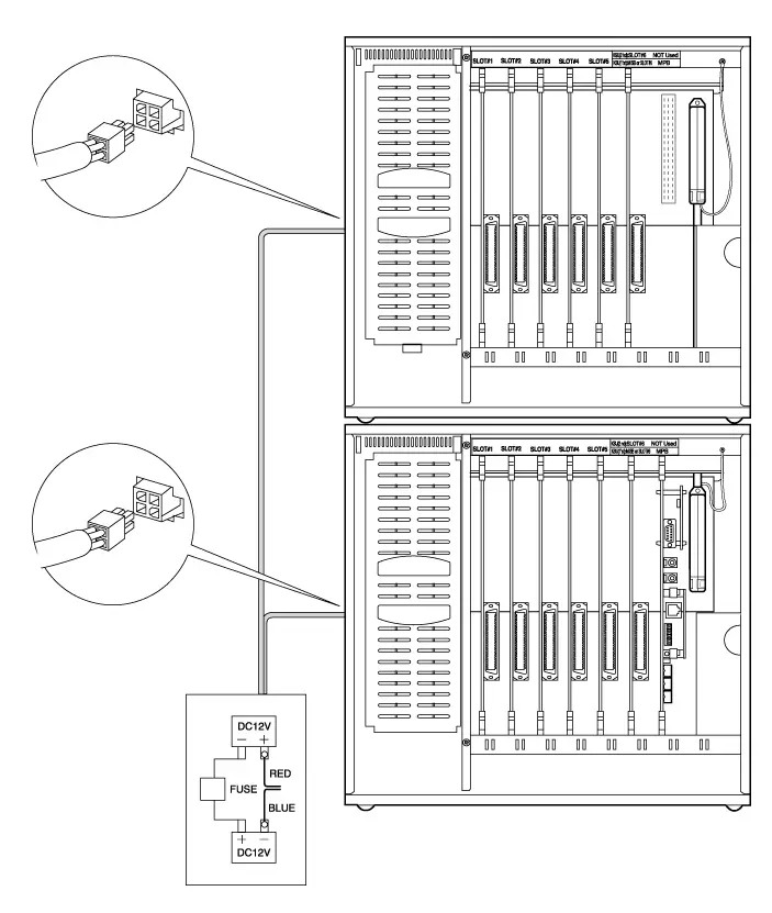
Fuse Rating
1st KSU :10A
1stKSU+2nd KSU:20A
Figure 3.5.1 Battery Back-up wiring
* Note: The cable for the battery connection is supplied with KSU in the same package.
The external batteries must provide 24 Volts DC. This is generally accomplished by connecting two 12 volt batteries in a series arrangement. Operation on batteries is controlled by the PSU. This ARIA-130 PSU will provide charging current to the batteries during normal AC power operation at a maximum of about 500 mA. During battery operation, the battery operation of PSU will be stop if the AC power re-applied or the battery voltage is too low to maintain proper system operation.
The length of time that the system will operate on the batteries is dependent on several elements including, battery charging state, condition of the batteries, capacity of the batteries, and the size of the system (number of station ports). The chart below gives the approximate back-up time for several system sizes and different battery capacities in ampere-hours.
| Battery Capacity | DKTU 24 Ports | DKTU 48 ports | DKTU 72 ports |
| 20AH | 6 hours | 4.5 hours | 3 hours |
| 40AH | 12 hours | 9 hours | 6 hours |
Table 3.5.1 Battery capacity
RS-232C Wiring on MPB and SIU
MPB contains one standard RS-232C interface and SIU on MPB contains one standard RS-232C interfaces. RS-232C is connected by 9-pin “D” connector as shown in Figure 3.5.2. Wiring connector for RS-232C must include the Clear to Send(CTS) lead if it is enabled by Switch position 2 of the MPB. It is recommended that the communication setting is 19200 BPS, 8 bits, no parity and 1 stop bit. But CN4 for SMC1 Port dose not support the RTS, CTS signal.
Cable for the connection with Terminal(DTE) is not supplied by LGE because of getting it easily.
For various application, Administration Programming is required according to the desired application.
DB-25 connector
for RS-232C
on Terminal
Name Function
TD Transmitted Data
RD Received Data
RTS Request To Send
CTS Clear To Send
DTR Data Terminal Ready
DSR Data Set Ready
SG Signal Ground
RD
TD
DTR
DSR
RTS
CTS
SG
TD
RD
DSR
DTR
CTS
RTS
SG
3
2
20
6
4
5
7
2
3
4
6
7
8
5
DB-9 connector
for RS-232C
on Terminal
RD
TD
DTR
DSR
RTS
CTS
SG
TD
RD
DSR
DTR
CTS
RTS
SG
2
3
4
6
7
8
5
5
8
7
6
4
3
2
DB-9 connector
for RS-232C of
CN21 on MPB
and SIU on MPB
DB-9 connector
for RS-232C of
CN21 on MPB
and SIU on MPB
Figure 3.5.2 Pin assignments and wiring of DB25 and DB9 for RS-232C
- Note:
- Protective Ground (Frame Ground) may be used between DTE and DCE(GDK system) for more stable communication. And it is recommended.
In DTEs and DCEs, protective ground (frame ground) is a point which is electrically bonded to the equipment frame. Protective ground (frame ground) is not an interchange circuit in RS-232C standard.(EIA/TIA-232-F) If bonding of the equipment frames of the DCE and the DTE is necessary, a separate conductor should be used which confirms to the appropriate national or local electrical codes.
MISB wiring
MISB provides connections for 2 music sources, 2 external page ports, 4 relay contact controls, and an alarm/door-bell input monitor through RJ21 type female connector. Table 3.5.2 shows the contact assignments of RJ21 type connector on MISB.
The cable with RJ21 type male connector is required to connect with terminal or external devices. It is possible to get the cable locally, or use GDK-162 5MC2 supplied by LGE on the order if necessary.
External Music Source wiring
MISB is capable of accommodating up to 2 ports of External Music Sources through 2 pairs of a RJ21 type connector, CHAMP1 on the board.
MOH1: Pin No. 11 and Pin No. 36
MOH2: Pin No. 12 and Pin No. 37
The level can be adjusted in 0.5 dB steps to ±20 dB of the input. Note, if the output of the source is too high or low, it will be necessary to lower or raise the output level control at the source.
The above External Music sources including an Internal Music Source on MPB are selectable by Admin Programming. See Programming Manual.
External Paging wiring
MISB supports up to 2 External Paging ports through 2 pairs of a RJ21 type connector, CHAMP1 on the board.
EXP1: Pin No. 13 and Pin No. 38
EXP2: Pin No. 14 and Pin No. 39
The above External Music sources are selectable by Admin Programming.
External DC
Power Supply
External
Amplifier
Ext. paging
output
MDF
MISB
RJ21 type connector, CHAMP1
1
26
13
38
Figure 3.5.3.a An example of External paging wiring
Relay contacts for general purpose
MISB supports up to 4 Relay contacts, which can be used for the functions of Loud Control, Door Open and so on under the software control. These relay contacts are respectively connected with external equipment through 4 pairs of a RJ21 type connector, CHAMP1 on the board.
RLY1: Pin No. 1 and Pin No. 26
RLY2: Pin No. 2 and Pin No. 27
RLY3: Pin No. 3 and Pin No. 28
RLY4: Pin No. 4 and Pin No. 29
External DC
Power Supply
MDF
MISB
RJ21 type connector, CHAMP1
2
27
Figure 3.5.3.b An example of Loud Bell wiring
Alarm Detection wiring
MISB provides an external alarm detection input, which can be used to notify to extensions when the external switch is on/off. This alarm detection input is provided through a pair of a RJ21 type connector, CHAMP1 on the board.
ALARM: Pin No. 18 and Pin No. 43
Close or open detection is programmable by Admin. Programming.
MDF
MISB
RJ21 type connector, CHAMP1
18
43
External Switch
Figure 3.5.3.c An example of External Switch wiring
Table 3.5.2 shows the contact assignments of RJ21 type female connector on MISB.
| RJ21 | MISB connector | MISB | |||
| Pin | Pair | Pin | Color-Code | Designation | |
| 1 | 1 | 26 | WH/BL | RLY1-R | |
| 26 | 1 | BL/WH | RLY1-T | ||
| 2 | 2 | 27 | WH/OR | RLY2-R | |
| 27 | 2 | OR/WH | RLY2-T | ||
| 3 | 3 | 28 | WH/GN | RLY3-R | |
| 28 | 3 | GN/WH | RLY3-T | ||
| 4 | 4 | 29 | WH/BN | RLY4-R | |
| 29 | 4 | BN/WH | RLY4-T | ||
| 5 | 5 | 30 | WH/SL | ||
| 30 | 5 | SL/WH | |||
| 6 | 6 | 31 | RD/BL | ||
| 31 | 6 | BL/RD | |||
| 7 | 7 | 32 | RD/OR | ||
| 32 | 7 | OR/RD | |||
| 8 | 8 | 33 | RD/GN | ||
| 33 | 8 | GN/RD | |||
| 9 | 9 | 34 | RD/BN | ||
| 34 | 9 | BN/RD | |||
| 10 | 10 | 35 | RD/SL | ||
| 35 | 10 | SL/RD | |||
| 11 | 11 | 36 | BK/BL | MOH1-R | |
| 36 | 11 | BL/BK | MOH1-T | ||
| 12 | 12 | 37 | BK/OR | MOH2-R | |
| 37 | 12 | OR/BK | MOH2-T | ||
| 13 | 13 | 38 | BK/GN | EXP1-R | |
| 38 | 13 | GN/BK | EXP1-T | ||
| 14 | 14 | 39 | BK/BN | EXP2-R | |
| 39 | 14 | BN/BK | EXP2-T | ||
| 15 | 15 | 40 | BK/SL | ||
| 40 | 15 | SL/BK | |||
| 16 | 16 | 41 | YL/BL | ||
| 41 | 16 | BL/YL | |||
| 17 | 17 | 42 | YL/OR | ||
| 42 | 17 | OR/YL | |||
| 18 | 18 | 43 | YL/GN | ALARM-R | |
| 43 | 18 | GN/YL | ALARM-T | ||
| 19 | 19 | 44 | YL/BN | ||
| 44 | 19 | BN/YL | |||
| 20 | 20 | 45 | YL/SL | ||
| 45 | 20 | SL/YL | BL:BLUE | ||
| 21 | 21 | 46 | VI/BL | BK:BLACK | |
| 46 | 21 | BL/VI | BN:BROWN | ||
| 22 | 22 | 47 | VI/OR | OR:ORANGE | |
| 47 | 22 | OR/VI | WH:WHITE | ||
| 23 | 23 | 48 | VI/GN | GN:GREEN | |
| 48 | 23 | GN/VI | SL: SILVER | ||
| 24 | 24 | 49 | VI/BN | VI:VIOLET | |
| 49 | 24 | BN/VI | RD:RED | ||
| 25 | 25 | 50 | VI/SL | YL:YELLOW | |
| 50 | 25 | SL/VI | |||
Table 3.5.2 MISB Wiring
Extension Board wiring
Extension boards such as DTIB12, DTIB24, DSIB, SLIB24, SLIB48, SLIB II and SLIB2E contain a RJ21 type female connector for station wiring to each interface circuit on each board.
But WTIB and WTIU, Wireless Terminal Interface Board/Unit for DECT contain RJ11 type jacks. (Refer to the section 5)
The following provides details on the interconnection between each type of Extension Board and the jack on the station.
Digital Keyset and Terminal wiring
Wiring from digital terminal interface board such as DTIB12, DTIB24 and DSIB to station jack requires one pair of wire. The power for a station, PCM data and signaling between board and station are transmitted over this pair.
Contact assignments of RJ11 type jack in Digital Terminals
Figure 3.5.4.a shows the contact assignments of the miniature 6-position jack (RJ11 type jack) in LG proprietary digital terminals. Two wires from the digital terminal interface of the system are basically connected to the contact numbers 3 (R) and 4(T).
But two additional contacts, R1 and T1 are provided in the digital terminal as shown in Figure 3.5.4.a. The contact number 3 (R) and 2 (R1) are connected together in the digital terminals, and also the contact number 4 (T) and 5 (T1) are connected together. Because there is a country in which the contact number 2 and 5 are used for the 2-wire connection method according to his local regulation. So LGE provide two more contacts, R1 and T1 in the digital terminals so that the special customer can use the line cord, which is in wide use in his country.
But only 2-wire connection should be recommended to get better transmission characteristics between digital terminal interface of the system and digital terminals.
T
T1
R
R1
1
2
3
4
5
6
Figure 3.5.4.a contact assignments of Digital Terminals
Connection method between the digital interfaces and the digital terminals
The cable with 25-pair male connector is required between Digital Terminal Interface board and MDF. It is possible to get the cable locally, or use GDK-162 5MC2 supplied by LGE on the order if necessary.
The MDF that is in wide use in the country can be locally used according to the requirements of local regulation.
MDF
1
2
3
4
5
6
ARIA-130 DTIB12/DTIB24/DSIB
RJ21 type
connector
on the board
1
26
2
27
3
28
4
29
DT1
DR1
DT2
DR2
DT3
DR3
Area A
Area B
Area C
Area D
Area E
Figure 3.5.4.b Basic connection method between digital terminal
interface of the system and digital terminal
- Note:
- Digital terminals operate regardless of line polarity, not with a fixed polarity.
- Each area means the followings,
A: LDK system, B: between the LDK system and MDF, C: cable in building,
D: between Terminal connection point, e.g. terminating adapter and Terminal,
E: digital terminals
- DTIB12 is capable of connecting to up to 12 digital terminals.
DTIB24 is capable of connecting to up to 24 digital terminals.
DSIB is capable of connecting to up to 6 digital terminals.
Connection method with special condition between the digital interfaces and the digital terminals
Only two-wire connection between the digital terminal interface and digital terminals is recommended to reduce the line noise exited from useless wires. Because R and R1/T and T1 are connected together in the terminals for various national conditions, the useless wires can cause the environment noise, which may affect the data transmission, to flow in the digital terminal the 4-wire line cord is used.
In this case, cut or remove the useless wires connected the contact number R1 and T1 (or, R and T) of the terminals at the Terminal connection point, e.g. terminating adapter, so that those are not drawn out any more.
Area E
Area D
Area C
Area B
Area A
MDF
1
2
3
4
5
6
ARIA-130 DTIB12/DTIB24/DSIB
RJ21 type
connector
on the board
1
26
2
27
3
28
4
29
DT1
DR1
DT2
DR2
DT3
DR3
1
2
3
4
5
6
Figure 3.5.4.c Connection method when the 4-wire line cord, or special
connection method with contact number 2 and 5.
- Note:
- Each area means the followings,
A: LDK system, B: between the LDK system and MDF, C: cable in building,
D: between Terminal connection point, e.g. terminating adapter and Terminal,
E: digital terminals
2. Only two wires should be connected to digital terminals and Interface Board, so the rest should be removed at MDF or Terminal Connection Point, as X points shown in above Figure.
Pin Assignments of RJ21 type jack on DTIB12/DTIB24/DSIB
See the clause 3.5.4.5 contact assignments of RJ21 type connector on extension board.
Single line Telephone wiring
SLT interface boards such as SLIB24, SLIB48, SLIB II, SLIB2E and DSIB are wired to SLT or standard analog device with a single pair of wire that provides battery feed, voice and signaling from/to the connected SLT. Typical contact assignments of RJ11 type jack, a miniature 6-position jack as following Figure 3.5.5.a. But the contact assignments and connector type may be different from following Figure in special countries according to the special national condition. Before wiring, it is important to check them.
Registered Jack
specified in FCC, CFR
1
2
3
4
5
6
T
R
Figure 3.5.5.a contact assignments of SLT
The cable with 25-pair male connector is required between SLT Interface board and MDF. It is possible to get the cable locally, or use GDK-162 5MC2 supplied by LGE on the order if necessary.
The MDF that is in wide use in the country can be locally used according to the requirements of local regulation.
RJ11 socket
on SLT
RJ21 type connector on board
SLIB24,SLIB48, SLIB II,
SLIB2E,DSIB
T3
R3
T2
R2
T1
R1
4
29
3
28
2
27
1
26
1
2
3
4
5
6
MDF
Figure 3.5.5.b wiring between board and analog TE including SLT
● Note:
- SLT(TE) typically operates with both polarities, since a fixed polarity is not guaranteed according to most of specification.
- SLIB24 and SLIB48 are respectively capable of connecting with up to 6 SLT.
SLIB II and SLIB2E are capable of connecting with up to 12 SLTs.
DSIB is capable of connecting with up to 6 SLTs from 7th pair of RJ21 type connector.
Intercom/Door Phone Box installation
The Intercom/Door Phone Box is intended to be wall mounted. There are two kinds of Intercom/Door Phone Boxes in ARIA-130 system available. KD-Digital Phone Box can be connected to the digital terminal interface.
First, separate the ICM/Door Box from the base plate by inserting a flat thin edged screw driver in the bottom of the product. Press the screw driver inward which will release the retaining tan and twist the screw driver to separate the base plate. Fasten the base plate of the ICM/Door Box to the wall with #8 screws. Route the cable through the cable entry hole in the base plate and connect the wires to the four screw terminals as shown in the Figure 3.5.6. When the wiring is complete, pull any slack wire back through the base plate and push the housing back together.
Connection method between the Digital Interface Board and KD-Digital Phone Box
KD-Digital Phone Box can be only connected to the Digital Interface Board. Wiring from digital terminal interface board to KD-Digital Phone Box requires one pair of wire.
MDF
ARIA-130 Digital Interface Board
RJ21 type connector
on the board
1
26
2
27
3
28
4
29
DT1
DR1
DT2
DR2
DT3
DR3
The soldering
side of
KD-Digital Phone Box
GR
RD
Figure 3.5.6 wiring between the board and KD-Digital Phone Box
Note: KD-Digital Phone Box operates regardless of line polarity, not with a fixed polarity.
MOHU installation
The MOHU (Music On Hold Unit) provides External Music Source to the system by connecting to any type of Single Line Interface including 2B-SLIU30 of the ARIA-130 system. The External Music Source provided by Single Line Interface is used as music source of MOH channel for System Hold, Background Music and ICM Box Music.
The MOHU has two connections for 2 external music sources (MOH) and 2 Single Line Interfaces (PORT).
– The ‘PORT 1’ is connected to the ‘MOH 1’.
– The ‘PORT 2’ is connected to the ‘MOH 2’.
The maximum distance of the installation is 1 Km (3.2 Kft) from the system.
ARIA-130 system is capable of accommodating up to 5 external music sources through 5 single line interfaces, which are limited by the main program.
To use the external music sources through the desired SLT ports, assign the desired SLT ports in the Admin program field #1 and 2nd button. For more details, see the Programming Manual.
External
Music
Source 1
ARIA-130
Single Line
Interface
(SLT port)
External
Music
Source 2
PORT1 PORT2
MOH2 MOH1
GDK-162/100(MOHU)
MUSIC ON HOLD UNIT

- Note :
It is recommended that the MOHU should not be installed in the humid place and the place that ESD (Electrostatic Discharge) occurs.
Figure 3.5.7 Connection method of MOHU
Contact Assignments of RJ21 Type Connectors on Extension Boards
Table 3.5.3.a shows the contact assignments of RJ21 type connector on DTIB12/DTIB24.
| Rj21 | DTIB connector | DTIB | Port | ||||
| Pin | Pair | Pin | Color-Code | Designation | No | ||
| 1 | 1 | 26 | WH/BL | DT-1 | 0 | DTIB12/24 | |
| 26 | 1 | BL/WH | DR-1 | ||||
| 2 | 2 | 27 | WH/OR | DT-2 | 1 | ||
| 27 | 2 | OR/WH | DR-2 | ||||
| 3 | 3 | 28 | WH/GN | DT-3 | 2 | ||
| 28 | 3 | GN/WH | DR-3 | ||||
| 4 | 4 | 29 | WH/BN | DT-4 | 3 | ||
| 29 | 4 | BN/WH | DR-4 | ||||
| 5 | 5 | 30 | WH/SL | DT-5 | 4 | ||
| 30 | 5 | SL/WH | DR-5 | ||||
| 6 | 6 | 31 | RD/BL | DT-6 | 5 | ||
| 31 | 6 | BL/RD | DR-6 | ||||
| 7 | 7 | 32 | RD/OR | DT-7 | 6 | ||
| 32 | 7 | OR/RD | DR-7 | ||||
| 8 | 8 | 33 | RD/GN | DT-8 | 7 | ||
| 33 | 8 | GN/RD | DR-8 | ||||
| 9 | 9 | 34 | RD/BN | DT-9 | 8 | ||
| 34 | 9 | BN/RD | DR-9 | ||||
| 10 | 10 | 35 | RD/SL | DT-10 | 9 | ||
| 35 | 10 | SL/RD | DR-10 | ||||
| 11 | 11 | 36 | BK/BL | DT-11 | 10 | ||
| 36 | 11 | BL/BK | DR-11 | ||||
| 12 | 12 | 37 | BK/OR | DT-12 | 11 | ||
| 37 | 12 | OR/BK | DR-12 | DTIB12/24 | |||
| 13 | 13 | 38 | BK/GN | DT-13 | 12 | DTIB24 only | |
| 38 | 13 | GN/BK | DR-13 | ||||
| 14 | 14 | 39 | BK/BN | DT-14 | 13 | ||
| 39 | 14 | BN/BK | DR-14 | ||||
| 15 | 15 | 40 | BK/SL | DT-15 | 14 | ||
| 40 | 15 | SL/BK | DR-15 | ||||
| 16 | 16 | 41 | YL/BL | DT-16 | 15 | ||
| 41 | 16 | BL/YL | DR-16 | ||||
| 17 | 17 | 42 | YL/OR | DT-17 | 16 | ||
| 42 | 17 | OR/YL | DR-17 | ||||
| 18 | 18 | 43 | YL/GN | DT-18 | 17 | ||
| 43 | 18 | GN/YL | DR-18 | ||||
| 19 | 19 | 44 | YL/BN | DT-19 | 18 | ||
| 44 | 19 | BN/YL | DR-19 | ||||
| 20 | 20 | 45 | YL/SL | DT-20 | 19 | ||
| 45 | 20 | SL/YL | DR-20 | BL:BLUE | |||
| 21 | 21 | 46 | VI/BL | DT-21 | 20 | BK:BLACK | |
| 46 | 21 | BL/VI | DR-21 | BN:BROWN | |||
| 22 | 22 | 47 | VI/OR | DT-22 | 21 | OR:ORANGE | |
| 47 | 22 | OR/VI | DR-22 | WH:WHITE | |||
| 23 | 23 | 48 | VI/GN | DT-23 | 22 | GN:GREEN | |
| 48 | 23 | GN/VI | DR-23 | SL: SILVER | |||
| 24 | 24 | 49 | VI/BN | DT-24 | 23 | VI:VIOLET | |
| 49 | 24 | BN/VI | DR-24 | RD:RED | |||
| 25 | 25 | 50 | VI/SL | – | – | YL:YELLOW | |
| 50 | 25 | SL/VI | – | – | |||
Table 3.5.3.a DTIB12/DTIB24 Wiring
Table 3.5.3.b shows the contact assignments of RJ21 type connector on SLIB24/SLIB48 and SLIBII/SLIB2E.
| RJ21 Pin | SLIB connector (SLIB24/SLIB48/SLIB II/SLIB2E) | SLIB | Port No | ||||
| Pair | Pin | Color-Code | Designation | ||||
| 1 | 1 | 26 | WH/BL | VT-1 | 0 | SLIB24/48, | |
| 26 | 1 | BL/WH | VR-1 | SLIBII/SLIB2E | |||
| 2 | 2 | 27 | WH/OR | VT-2 | 1 | ||
| 27 | 2 | OR/WH | VR-2 | ||||
| 3 | 3 | 28 | WH/GN | VT-3 | 2 | ||
| 28 | 3 | GN/WH | VR-3 | ||||
| 4 | 4 | 29 | WH/BN | VT-4 | 3 | ||
| 29 | 4 | BN/WH | VR-4 | ||||
| 5 | 5 | 30 | WH/SL | VT-5 | 4 | ||
| 30 | 5 | SL/WH | VR-5 | ||||
| 6 | 6 | 31 | RD/BL | VT-6 | 5 | SLIB24/48, | |
| 31 | 6 | BL/RD | VR-6 | SLIBII/SLIB2E | |||
| 7 | 7 | 32 | RD/OR | VT-7 | 6 | SLIB II/SLIB2E | |
| 32 | 7 | OR/RD | VR-7 | ||||
| 8 | 8 | 33 | RD/GN | VT-8 | 7 | ||
| 33 | 8 | GN/RD | VR-8 | ||||
| 9 | 9 | 34 | RD/BN | VT-9 | 8 | ||
| 34 | 9 | BN/RD | VR-9 | ||||
| 10 | 10 | 35 | RD/SL | VT-10 | 9 | ||
| 35 | 10 | SL/RD | VR-10 | ||||
| 11 | 11 | 36 | BK/BL | VT-11 | 10 | ||
| 36 | 11 | BL/BK | VR-11 | ||||
| 12 | 12 | 37 | BK/OR | VT-12 | 11 | ||
| 37 | 12 | OR/BK | VR-12 | ||||
| 13 | 13 | 38 | BK/GN | – | – | ||
| 38 | 13 | GN/BK | – | ||||
| 14 | 14 | 39 | BK/BN | – | – | ||
| 39 | 14 | BN/BK | – | ||||
| 15 | 15 | 40 | BK/SL | – | – | ||
| 40 | 15 | SL/BK | – | ||||
| 16 | 16 | 41 | YL/BL | – | – | ||
| 41 | 16 | BL/YL | – | ||||
| 17 | 17 | 42 | YL/OR | – | – | ||
| 42 | 17 | OR/YL | – | ||||
| 18 | 18 | 43 | YL/GN | – | – | ||
| 43 | 18 | GN/YL | – | ||||
| 19 | 19 | 44 | YL/BN | – | – | ||
| 44 | 19 | BN/YL | – | ||||
| 20 | 20 | 45 | YL/SL | – | – | ||
| 45 | 20 | SL/YL | – | BL:BLUE | |||
| 21 | 21 | 46 | VI/BL | – | – | BK:BLACK | |
| 46 | 21 | BL/VI | – | BN:BROWN | |||
| 22 | 22 | 47 | VI/OR | – | – | OR:ORANGE | |
| 47 | 22 | OR/VI | – | WH:WHITE | |||
| 23 | 23 | 48 | VI/GN | – | – | GN:GREEN | |
| 48 | 23 | GN/VI | – | SL: SILVER | |||
| 24 | 24 | 49 | VI/BN | – | – | VI:VIOLET | |
| 49 | 24 | BN/VI | – | RD:RED | |||
| 25 | 25 | 50 | VI/SL | – | – | YL:YELLOW | |
| 50 | 25 | SL/VI | – | ||||
Table 3.5.3.b SLIB24/SLIB48, SLIBII/SLIB2E Wiring
Table 3.5.3.c shows the contact assignments of RJ21 type connector on DSIB.
| RJ21 | DSIB connector | DSIB | Port | ||||
| Pin | Pair | Pin | Color-Code | Designation | No | ||
| 1 | 1 | 26 | WH/BL | DT-1 | 0 (DKT 0) | DKT I/F | |
| 26 | 1 | BL/WH | DR-1 | ||||
| 2 | 2 | 27 | WH/OR | DT-2 | 1 (DKT 1) | ||
| 27 | 2 | OR/WH | DR-2 | ||||
| 3 | 3 | 28 | WH/GN | DT-3 | 2 (DKT 2) | ||
| 28 | 3 | GN/WH | DR-3 | ||||
| 4 | 4 | 29 | WH/BN | DT-4 | 3 (DKT 3) | ||
| 29 | 4 | BN/WH | DR-4 | ||||
| 5 | 5 | 30 | WH/SL | DT-5 | 4 (DKT 4) | ||
| 30 | 5 | SL/WH | DR-5 | ||||
| 6 | 6 | 31 | RD/BL | DT-6 | 5 (DKT 5) | ||
| 31 | 6 | BL/RD | DR-6 | ||||
| 7 | 7 | 32 | RD/OR | VT-1 | 6 (SLT 0) | SLT I/F | |
| 32 | 7 | OR/RD | VR-1 | ||||
| 8 | 8 | 33 | RD/GN | VT-2 | 7 (SLT 1) | ||
| 33 | 8 | GN/RD | VR-2 | ||||
| 9 | 9 | 34 | RD/BN | VT-3 | 8 (SLT 2) | ||
| 34 | 9 | BN/RD | VR-3 | ||||
| 10 | 10 | 35 | RD/SL | VT-4 | 9 (SLT 3) | ||
| 35 | 10 | SL/RD | VR-4 | ||||
| 11 | 11 | 36 | BK/BL | VT-5 | 10 (SLT 4) | ||
| 36 | 11 | BL/BK | VR-5 | ||||
| 12 | 12 | 37 | BK/OR | VT-6 | 11 (SLT 5) | ||
| 37 | 12 | OR/BK | VR-6 | ||||
| 13 | 13 | 38 | BK/GN | ||||
| 38 | 13 | GN/BK | |||||
| 14 | 14 | 39 | BK/BN | ||||
| 39 | 14 | BN/BK | |||||
| 15 | 15 | 40 | BK/SL | ||||
| 40 | 15 | SL/BK | |||||
| 16 | 16 | 41 | YL/BL | ||||
| 41 | 16 | BL/YL | |||||
| 17 | 17 | 42 | YL/OR | ||||
| 42 | 17 | OR/YL | |||||
| 18 | 18 | 43 | YL/GN | ||||
| 43 | 18 | GN/YL | |||||
| 19 | 19 | 44 | YL/BN | ||||
| 44 | 19 | BN/YL | |||||
| 20 | 20 | 45 | YL/SL | ||||
| 45 | 20 | SL/YL | BL:BLUE | ||||
| 21 | 21 | 46 | VI/BL | BK:BLACK | |||
| 46 | 21 | BL/VI | BN:BROWN | ||||
| 22 | 22 | 47 | VI/OR | OR:ORANGE | |||
| 47 | 22 | OR/VI | WH:WHITE | ||||
| 23 | 23 | 48 | VI/GN | GN:GREEN | |||
| 48 | 23 | GN/VI | SL: SILVER | ||||
| 24 | 24 | 49 | VI/BN | VI:VIOLET | |||
| 49 | 24 | BN/VI | RD:RED | ||||
| 25 | 25 | 50 | VI/SL | YL:YELLOW | |||
| 50 | 25 | SL/VI | |||||
* I/F: Interface
Table 3.5.3.c DSIB Wiring
PFTU Wiring
The PFTU is wired from the RJ21 type male connector on the module itself to the MDF, cross connected to the CO Line inputs from the telephone company, to the CO Line inputs of the system, and to Power Failure SLTs. The CO lines and SLTs are used as CO line inputs and extensions of ARIA-130 System in normal operation, but each CO line and SLT is directly connected in power failure mode by connecting as shown in Figure 3.5.8.
The cable with RJ21 type female connector is required between PFTU connector and MDF. It is possible to get the cable locally, or use GDK-162 5MC1 supplied by LGE on the order if necessary.
The MDF that is in wide use in your country can also be locally used according to the requirements of local regulation.
MDF
1
26
4
29
SLIB1-T
SLIB1-R
PFTU
25
50
COT1-IN
COR1-IN
2
27
COT1-OUT
COR1-OUT
3
28
TEL1-T
TEL1-R
SLIB interface
CO line
LCOB interface
SLT
RJ21 type connector in PFTU
Connected to MB Basic
Connected to
another PFTU
Figure 3.5.8 PFTU wiring
- Note:
- A connector block with screws, which is connected to MB Basic (Back plane), is supplied in the PFTU package, but control wires are not supplied. It is recommended that 2 wires with AWG 22, 24 or 26 be used for the connection of control signal.
2. The control wires can be connected regardless of their polarities.
Table 3.5.4 shows the contact assignments of RJ21 type connector on PFTU.
| RJ21 | PFTU connector | PFTU | PFT | |||
| Pin | Pair | Pin | Color-Code | Designation | Circuit | |
| 1 | 1 | 26 | WH/BL | COT1-IN | 1st Circuit | |
| 26 | 1 | BL/WH | COR1-IN | |||
| 2 | 2 | 27 | WH/OR | COT1-OUT | ||
| 27 | 2 | OR/WH | COR1-OUT | |||
| 3 | 3 | 28 | WH/GN | TEL1-T | ||
| 28 | 3 | GN/WH | TEL1-R | |||
| 4 | 4 | 29 | WH/BN | SLIB1-T | ||
| 29 | 4 | BN/WH | SLIB1-R | |||
| 5 | 5 | 30 | WH/SL | COT2-IN | 2nd Circuit | |
| 30 | 5 | SL/WH | COR2-IN | |||
| 6 | 6 | 31 | RD/BL | COT2-OUT | ||
| 31 | 6 | BL/RD | COR2-OUT | |||
| 7 | 7 | 32 | RD/OR | TEL2-T | ||
| 32 | 7 | OR/RD | TEL2-R | |||
| 8 | 8 | 33 | RD/GN | SLIB2-T | ||
| 33 | 8 | GN/RD | SLIB2-R | |||
| 9 | 9 | 34 | RD/BN | COT3-IN | 3rd Circuit | |
| 34 | 9 | BN/RD | COR3-IN | |||
| 10 | 10 | 35 | RD/SL | COT3-OUT | ||
| 35 | 10 | SL/RD | COR3-OUT | |||
| 11 | 11 | 36 | BK/BL | TEL3-T | ||
| 36 | 11 | BL/BK | TEL3-R | |||
| 12 | 12 | 37 | BK/OR | SLIB3-T | ||
| 37 | 12 | OR/BK | SLIB3-R | |||
| 13 | 13 | 38 | BK/GN | COT4-IN | 4th Circuit | |
| 38 | 13 | GN/BK | COR4-IN | |||
| 14 | 14 | 39 | BK/BN | COT4-OUT | ||
| 39 | 14 | BN/BK | COR4-OUT | |||
| 15 | 15 | 40 | BK/SL | TEL4-T | ||
| 40 | 15 | SL/BK | TEL4-R | |||
| 16 | 16 | 41 | YL/BL | SLIB4-T | ||
| 41 | 16 | BL/YL | SLIB4-R | |||
| 17 | 17 | 42 | YL/OR | COT5-IN | 5th Circuit | |
| 42 | 17 | OR/YL | COR5-IN | |||
| 18 | 18 | 43 | YL/GN | COT5-OUT | ||
| 43 | 18 | GN/YL | COR5-OUT | |||
| 19 | 19 | 44 | YL/BN | TEL5-T | ||
| 44 | 19 | BN/YL | TEL5-R | |||
| 20 | 20 | 45 | YL/SL | SLIB5-T | ||
| 45 | 20 | SL/YL | SLIB5-R | BL:BLUE | ||
| 21 | 21 | 46 | VI/BL | COT6-IN | 6th Circuit | BK:BLACK |
| 46 | 21 | BL/VI | COR6-IN | BN:BROWN | ||
| 22 | 22 | 47 | VI/OR | COT6-OUT | OR:ORANGE | |
| 47 | 22 | OR/VI | COR6-OUT | WH:WHITE | ||
| 23 | 23 | 48 | VI/GN | TEL6-T | GN:GREEN | |
| 48 | 23 | GN/VI | TEL6-R | SL: SILVER | ||
| 24 | 24 | 49 | VI/BN | SLIB6-T | VI:VIOLET | |
| 49 | 24 | BN/VI | SLIB6-R | RD:RED | ||
| 25 | 25 | 50 | VI/SL | – | – | YL:YELLOW |
| 50 | 25 | SL/VI | – | |||
Table 3.5.4 PFTU Wiring
Analog CO Line wiring
Analog CO boards such as LCOB and LCOB8 contain a RJ21 type male connector to connect to analog CO line on each board. The following provides details on the connection of each type of analog CO line Board.
LCOB wiring
LCOB and LCOB8 are capable of connecting 4/8 loop start CO lines through a RJ21 type male connector on the board.
The cable with RJ21 type female connector is required between PFTU connector and MDF. It is possible to get the cable locally, or use GDK-162 5MC1 supplied by LGE on the order if necessary.
The MDF that is in wide use in the country can be locally used according to the requirements of local regulation.
MDF
1
26
4
29
T4
R4
LCOB / LCOB8
RJ21 type connector on board
25
50
T1
R1
2
27
T2
R2
3
28
T3
R3
Network
Figure 3.5.9 loop start CO line wiring
- Note:
- CO lines of LCOB and LCOB8 can operate regardless of line polarity.
- Connect TRC (Telecommunication reference cable) to 25th pair of RJ21 type connector if it is supplied from Network.
- LCOB is capable of connecting up to 4 lines.
4. LCOB8 is capable of connecting up to 8 lines.
Contact Assignments of RJ21 type Connectors on Analog CO Boards
Table 3.5.5 shows the contact assignments of RJ21 type connector on LCOB and LCOB8.
| RJ21 | LCOB, LCOB8 connector | LCOB | Line | |||
| Pin | Pair | Pin | Color-Code | Designation | No | |
| 1 | 1 | 26 | WH/BL | CO1-T | 1 | LCOB, LCOB8 |
| 26 | 1 | BL/WH | CO1-R | |||
| 2 | 2 | 27 | WH/OR | CO2-T | 2 | |
| 27 | 2 | OR/WH | CO2-R | |||
| 3 | 3 | 28 | WH/GN | CO3-T | 3 | |
| 28 | 3 | GN/WH | CO3-R | |||
| 4 | 4 | 29 | WH/BN | CO4-T | 4 | |
| 29 | 4 | BN/WH | CO4-R | |||
| 5 | 5 | 30 | WH/SL | CO5-T | 5 | LCOB8 only |
| 30 | 5 | SL/WH | CO5-R | |||
| 6 | 6 | 31 | RD/BL | CO6-T | 6 | |
| 31 | 6 | BL/RD | CO6-R | |||
| 7 | 7 | 32 | RD/OR | CO7-T | 7 | |
| 32 | 7 | OR/RD | CO7-R | |||
| 8 | 8 | 33 | RD/GN | CO8-T | 8 | |
| 33 | 8 | GN/RD | CO8-R | |||
| 9 | 9 | 34 | RD/BN | |||
| 34 | 9 | BN/RD | ||||
| 10 | 10 | 35 | RD/SL | |||
| 35 | 10 | SL/RD | ||||
| 11 | 11 | 36 | BK/BL | |||
| 36 | 11 | BL/BK | ||||
| 12 | 12 | 37 | BK/OR | |||
| 37 | 12 | OR/BK | ||||
| 13 | 13 | 38 | BK/GN | |||
| 38 | 13 | GN/BK | ||||
| 14 | 14 | 39 | BK/BN | |||
| 39 | 14 | BN/BK | ||||
| 15 | 15 | 40 | BK/SL | |||
| 40 | 15 | SL/BK | ||||
| 16 | 16 | 41 | YL/BL | |||
| 41 | 16 | BL/YL | ||||
| 17 | 17 | 42 | YL/OR | |||
| 42 | 17 | OR/YL | ||||
| 18 | 18 | 43 | YL/GN | |||
| 43 | 18 | GN/YL | ||||
| 19 | 19 | 44 | YL/BN | |||
| 44 | 19 | BN/YL | ||||
| 20 | 20 | 45 | YL/SL | |||
| 45 | 20 | SL/YL | BL:BLUE | |||
| 21 | 21 | 46 | VI/BL | BK:BLACK | ||
| 46 | 21 | BL/VI | BN:BROWN | |||
| 22 | 22 | 47 | VI/OR | OR:ORANGE | ||
| 47 | 22 | OR/VI | WH:WHITE | |||
| 23 | 23 | 48 | VI/GN | GN:GREEN | ||
| 48 | 23 | GN/VI | SL: SILVER | |||
| 24 | 24 | 49 | VI/BN | VI:VIOLET | ||
| 49 | 24 | BN/VI | RD:RED | |||
| 25 | 25 | 50 | VI/SL | YL:YELLOW | ||
| 50 | 25 | SL/VI | TEGND | Tel Ground | LCOB8 only | |
Table 3.5.5 LCOB and LCOB8 Wiring
EMIB wiring
You don’t need to consider the polarity of 2 voice wires(for both transmit and receive path in 2 wire E&M or transmit path and receive path respectively in 4 wire E&M), but you should connect the Ear wire(-48V) of one system to the Mouth wire(open in the idle state) of the other system and the Mouth wire(open) of one system to the Ear wire(-48V) of the other system.
Both systems should be connected to common ground.
The pin assignment of the champ connector(CN3)
| The pin number | The assignment | Remark |
| A1 | 1RX_A | |
| B1 | 1RX_B | |
| A2 | 1TX_A | Used for the Port 1 |
| B2 | 1TX_B | |
| A3 | 1E | |
| B3 | 1M | |
| A4 | 2RX_A | |
| B4 | 2RX_B | |
| A5 | 2TX_A | Used for the Port 2 |
| B5 | 2TX_B | |
| A6 | 2E | |
| B6 | 2M | |
| The pin number | The assignment | Remark |
| A7 | 3RX_A | |
| B7 | 3RX_B | Used for the Port 3 |
| A8 | 3TX_A | |
| B8 | 3TX_B | |
| A9 | 3E | |
| B9 | 3M | |
| A10 | 4RX_A | |
| B10 | 4RX_B | |
| A11 | 4TX_A | Used for the Port 4 |
| B11 | 4TX_B | |
| A12 | 4E | |
| B12 | 4M | |
| A13~A25 | Not used | |
| B13~B25 | Not used |
EX) The wiring of 4-wire voice path
ARIA-130 system(or PABX)
ARIA-130 system
Voice path
Tx
Rx
(RX-A, RX-B)
(TX-A, TX-B)
Rx
Tx
(TX-A, TX-B)
(RX-A, RX-B)
Mouth(GND)
Ear(-48V)
Signal path
Ear(-48V)
Mouth(GND)
Vacant Section
VOIB wiring
The contact assignment of RJ45 type jack on VOIB is shown in Figure 3.5.11.
RX+
TX-
TX+
RX-
1
2
3
4
5
6
7
8
Figure 3.5.11 contact assignments of RJ-45 type jack of VOIB
T1
UTP, Category 5
.
.
●
●
●
SW1
LD9
.
.
.
.
LD14
Figure 3.5.12 Network Cable Connection
* Note :
– 10BASE-T runs on Category 3 UTP or higher.
– 100BASE-TX runs only on Category 5 UTP cable.
ISDN wiring
ISDN boards such as BRIB, STIB and PRIB contain RJ45 type jack on each board, to connect to ISDN.
Following Figure shows ISDN reference point and Functional group,
or

![]()
ISDN
PX
(LT)
ISDN Network
PC
G4-Fax
S
V,X
Terminal
SLT
NT2
TA
ISDN-TEL
NT1
NT1
U
U
T
S
R
V
The position of LDK-System
Figure 3.5.13.a ISDN Reference Points and Functional Group
Reference point: Theoretical point to classify the functional unit
- V-point: PX line
- U-point: Subscriber line
Subscriber line between public exchange and NT1 (Network termination), 2wire and 4~5Km distance.
- T-point: ISDN Trunk line
Trunk line for PBX between NT1 and PBX system, 4wire and 1Km max distance.
- S-point: ISDN standard user interface
Standard point for ISDN terminal connection, physically same as T-point, multiple connection possible.
- R-point: X or V series terminal interface.
Reference point between Terminal adapter and non-ISDN terminal connection.
Functional Units
- NT1: Network Termination
- NT2: Protocol Handle, PBX
- TE1: Standard ISDN interface TE
- TE2: Non-Standard ISDN interface TE
- TA : Adapter for non-standard ISDN interface
ISDN trunk connection (Basic Rate)
TR
TR
NT1
LDK System
ISDN Board
BRIB
STIB(T)
Max. 1000 meters
1. Point to Point connection
2. TR: Termination resistor, 100 ohm
Figure 3.5.13.b ISDN Trunk connection (Basic Rate Interface: T)
ISDN Terminal Connection (Basic Rate)
P to P Connection
TR
TR
LDK-SYSTEM
TR
STIB(S)
BRIB
STIB(T)
TR
TR
Max. 1000 meters
Max. 200 meters
TR
TR
Max. 500 meters
Max. 50 meters
P to MP Connection
– Short Passive
P to MP Connection
– Extended Passive
Figure 3.5.13.c ISDN Terminal connection (Basic Rate Interface: S)
- Connection Type
-. P to P: Point to Point connection
-. P to MP: Point to Multi-Point connection
- TR: Termination resistor, 100 ohm
-. This may be contained in a TE among multi-TEs.
ISDN Trunk connection (Primary Rate)
Max. 1000 meters
LDK System
ISDN Board
PRIB
DSU
Figure 3.5.13.d ISDN Trunk connection (Primary Rate Interface)
- Point to Point connection only
- Without power feed.
- Line Impedance: 120 ohm
Repeater
Physical Connectors
Basic Rate User network Interface
Fig 3.5.13.e RJ-45 Type Jack
1
2
3
4
5
6
7
8
ISO 8877
ITU-T Rec. I.430
Contact
1
2
3
4
5
6
7
8
TE
Power Source 3
Power Source 3
Transmit
Receive
Receive
Transmit
Power Source 2
Power Source 2
NT
Power Source 3
Power Source 3
Receive
Transmit
Transmit
Receive
Power Source 2
Power Source 2
Polarity
+
–
+
+
–
–
–
+
Table 3.5.6.a Contact assignments
Primary Rate User network Interface (E1/T1)
Fig 3.5.13.f RJ-45 Type Jack
1
2
3
4
5
6
7
8
ISO 10173
ANSI T1.408
Contact
1
2
3
4
5
6
7
8
TE
Receive
Receive
Shield(R) *
Transmit
Transmit
Shield(T) *
Power Source *
Power Source *
NT
Transmit
Transmit
Shield(T) *
Receive
Receive
Shield(R) *
Power Source *
Power Source *
Polarity
–
+
Table 3.5.6.b Contact assignments
* Optional
BRIB wiring
BRI lines are connected to BRIB/BRIU through RJ45 type jacks.
The contact assignment of RJ45 type jack on BRIB is shown in Figure 3.5.14.a.
1
2
3
4
5
6
7
8
RX+
RX-
TX-
TX+
Figure 3.5.14.a Contact assignment of RJ-45 type jack of BRIB
The TX pair of RJ45 type jack on BRIB/BRIU is connected to the RX pair of NT1, and the RX one on BRIB/BRIU is to the TX one of NT1 as Figure 3.5.14.b.
Terminating resistors should be required on each line to match line impedance. See clause 3.5.7.4
NT1 (NT-Box)
BRIB/BRIU
RJ45 type jack
TX+
TX-
RX+
RX-
3
6
4
5
3
6
4
5
RX+
RX-
TX+
TX-
From/to PX
Note:
- Connect the TX pair of an RJ45 type jack on BRIB/BRIU to the RX pair of NT1 and vice versa.
- Check terminating resistors. See clause 3.5.7.4.
3. BRIB is capable of connecting to up to 4 lines.
Figure 3.5.14.b BRI trunk line wiring
STIB wiring
STIB is capable of connecting to 4 Basic Rate Trunk lines or Terminals through RJ45 type jacks. Each line is switchable by hardware and software setting. (see clause 3.4.6.2)
The contact assignment of RJ45 type jack on STIB is shown in Figure 3.5.15.a.
1
2
3
4
5
6
7
8
TX+
TX-
RX-
RX+
1
2
3
4
5
6
7
8
RX+
RX-
TX-
TX+
a. When a line is set to T interface
b. When a line is set to S interface
Figure 3.5.15.a Contact assignment of RJ-45 Connectors of STIB
The TX pair of RJ45 type jack on STIB is connected to the RX pair of NT1 or Terminal, and the RX one on STIB/STIU is to the TX one of NT1 or terminal as Figure 3.5.15.b.
Terminating resistors should be required on each line to match line impedance. See clause 3.5.7.4.
NT1 (NT-Box)
STIB
RJ45 type jack
TX+
TX-
RX+
RX-
3
6
4
5
3
6
4
5
RX+
RX-
TX+
TX-
From/to PX
ISDN Terminal
RX+
RX-
TX+
TX-
3
6
4
5
3
6
4
5
TX+
TX-
RX+
RX-
S
T
SWx
S
T
SWx
OR
T interface
S interface
Note:
- Connect the TX pair of RJ45 type jack on STIB to the RX pair of NT1 and vice versa. And connect the TX pair of RJ45 type jack on STIB to a RX pair of ISDN terminal and vice versa.
- Check terminating resistors. See clause 3.5.7.4.
- SWx means selectable switches of S or T interface on each interface of STIB, see clause 3.4.6.2
- STIB is capable of connecting to up to 4 lines/terminals.
Figure 3.5.15.b STI trunk line (T) or terminal connection (S) wiring
PRIB wiring
PRIB of ARIA-130 supports only TE mode(slave), so ARIA-130 PRIB can not used as NT mode for Q-sig, but GDK-100 PRIB can be used as NT mode for Q-sig in ARIA-130 system.
PRIB is capable of connecting to 1 Primary Rate Trunk lines through an RJ45 type jack.
The contact assignment of RJ45 type jack on PRIB is shown in Figure 3.5.16.a.
1
2
3
4
5
6
7
8
RX
GND (T)
RX
TX
TX
GND (R)
- Note:
1. Only two pairs of RX and TX are typically connected with PRI line.
Figure 3.5.16.a Contact assignment of RJ-45 type jack of PRIB
The TX pair of RJ45 type jack on PRIB is connected to the RX pair of DSU, and the RX one on PRIB is to the TX one of DSU as Figure 3.5.16.b.
DSU (NT-Box)
PRIB
RJ45 type jack
RX
RX
TX
TX
1
2
4
5
1
2
4
5
TX
TX
RX
RX
From/to PX
- Note:
- Connect the TX pair of RJ45 type jack on PRIB to the RX pair of DSU and vice versa.
2. PRIB is capable of connecting with 1 PRI line.
Figure 3.5.16.b PRI trunk line (TE connection) wiring
PRIB card is typically used as TE connecting with ISDN PX and DSU. But the PRIB can be used as NT in special purpose such as QSIG function with another LDK/GDK PRIBs directly. However the type of contact assignment of RJ45 type jack is provided for TE connection on PRIB card, that is, the contact assignment of RJ45 type jack on PRIB is not changed even though the board is set to NT mode. See Table 3.5.6.b and Figure 3.5.16. So it is important that the wiring with contact assignment of RJ45 type connector should be checked, when PRIB is set to master mode (NT) during installation. The TX pair of RJ45 connector on PRIB in master mode is connected to the RX pair of PRIB of another system and vice versa as following Figure 3.5.16.c.
Another GDK/LDK system
PRIB/PRIU (TE mode)
GDK-100 PRIB (NT mode)
RJ45 connector
RX
RX-
TX
TX
1
2
4
5
1
2
4
5
RX
RX
TX
TX
- Note:
1. ARIA-130 PRIB supports only TE(slave) mode mode, not NT(master) mode.
2. When PRIB is set to NT mode, two pins of CON3 should be short by shorting traps, e.g. a short pin. See the clause 3.4.6.3 PRIB Installation; Function of Connectors.
Figure 3.5.16.c PRI line (NT connection) wiring
Terminating Resistors on Basic Rate interface(BRIB/STIB)
Terminating resistors are required on each line of BRIB/BRIU/STIB for the proper operation. Switchable terminating resistors are introduced on GDK-100 BRIB issue 3 or later version, GDK-100 STIB issue 2 or later version and ARIA-130 BRIB/BRIU issue 1 or later version. So switches on each line of the board should be ON to terminate them when installing line.
From/To
ISDN Terminal
BRIB / BRIU
STIB
RJ45 type jack
TX+
TX-
RX+
RX-
3
6
4
5
RX+
RX-
TX+
TX-
3
6
4
5
OR
T interface
: BRIB and
STIB (T)
S interface
: STIB (S)
SWx
R
R
ON
SWx
R
R
ON
From/To
BRI Line
- Note:
- R is 100 ohm terminating resistor, and the line is terminated at 100 ohm when switches are ON.
2. SWx means terminating switches on each interface of BRIB/STIB. See clause 3.4.6.
Figure 3.5.17.a Terminating method of BRIB/BRIU/STIB with switchable terminating resistors
But terminating resistors are not introduced on GDK-100 BRIB issue 2 and GDK-100 STIB issue 1, which versions are officially production stopped. So the external terminating unit should be required to terminate them if GDK-100 BRIB is issue 2 or earlier, and GDK-100 STIB is issue 1. The external terminating unit can be locally got, otherwise 2923NP1656, which is the terminating unit provided by LGE, can be used.
External terminating Unit
GDK-100 BRIB
GDK-100 STIB
RJ45 type jack
TX+
TX-
RX+
RX-
3
6
4
5
RX+
RX-
TX+
TX-
3
6
4
5
OR
T interface
: BRIB and
STIB (T)
S interface
: STIB (S)
From/To
BRI Line
From/To
ISDN Terminal
R
R
R
R
- Note: R is 100 ohm terminating resistors.
Figure 3.5.17.b Terminating method of BRIB/STIB without switchable terminating resistors
Clock Control Cable wiring- Multi ISDN board installation
ARIA-130 system allows Multi-ISDN boards to be installed. When Multi-ISDN board installation, clock control cable should be connected according to the priority of the cards. Then, in case that the ISDN line of the board with the higher priority is in the state of Loss of signal or clock failed, the synchronized clock for system will be supplied from next daisy chained ISDN board. Every ISDN card in TE mode generates the reference clock synchronized with ISDN line and transmits the clock to PLLU on MPB according to the clock control signal.
| High (1) state | Low (0) state | |
| IN | Enable the reference clock circuit | Disable the reference clock out circuit |
| OUT | Enable next clock circuit | Disable next clock circuit |
Table 3.5.7 clock control cable on ISDN board
MPB
PRIB
(TE mode)
BRIB
STIB
(T interface(s))
PLLU
Back Plane (Basic Mother Board)
OUT
IN
Priority
of Boards
<
<
OUT
IN
OUT
IN
BRI Line
TE
S
T
PRI Line
Figure 3.5.18.a Example of multi-ISDN boards installation when PRIB has the highest priority
Note:
- Clock control cables supplied by LGE should be connected between ISDN boards according to the priority of them when multi-ISDN boards installation.
- When PRIB is set to master (NT) mode, the clock cable connected with PRIB is not required.
MPB
BRIB
(the highest priority)
BRIB
STIB
(T interface(s))
PLLU
Back Plane (Basic Mother Board)
OUT
IN
Priority
of Boards
<
<
OUT
IN
OUT
IN
BRI Line
TE
S
T
Figure 3.5.18.b Example of multi-ISDN boards installation when BRIB has the highest priority
Note:
1. Clock control cables supplied by LGE should be connected between ISDN boards according to the priority of them when multi-ISDN boards installation
MPB
STIB
(T interface(s))
(the highest priority)
STIB
(T interface(s))
STIB
(all S interfaces)
PLLU
Back Plane (Basic Mother Board)
OUT
IN
Priority
of Boards
<
OUT
IN
OUT
IN
BRI Line
TE
S
TE
S
<
- Note:
- Clock control cables supplied by LGE should be connected between ISDN boards according to the priority of them when multi-ISDN board installation.
2. If all the lines of ISDN board are set to NT mode (S interface), clock control cable should be not connected to the board.
Figure 3.5.18.c Example of multi-ISDN boards installation when STIB has the highest priority
and all the interface of other STIBs are set to S interfaces.
The followings are the clock chain with the other ISDN board in the ARIA-130 system. There are three cases.
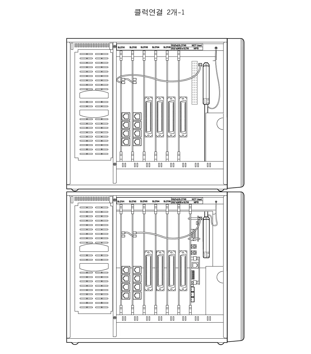
Lowest
Priority
Highest
Priority
Figure 3.5.19.a Case 2 of clock chain
Highest
Priority
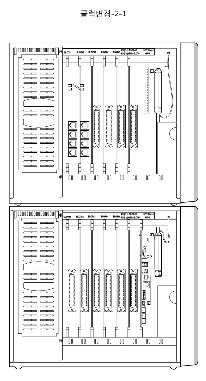
Figure 3.5.19.b Case 3 of clock chain
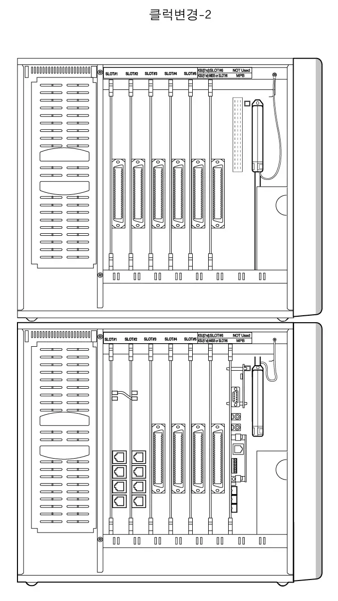
Highest
Priority
Figure 3.5.19.c Case 4 of clock chain
QSIG connection
ARIA-130 system supports QSIG function using ISDN boards. There are two kinds of connection for supporting QSIG function. One is the direct connection between LDK systems with PRI line, the other is the connection through Public Network with PRI or BRI lines.
Note : ARIA-130 PRIB(w/o CPU version) can not be used as NT(master mode) for Q-sig.
GDK-100 PRIB(w/ CPU version) can be used as NT9master mode) for Q-sig in ARIA-130
System.
Direct connection
Only GDK-100 PRIB boards can be used for the direct connection.
For more details, see the manual for GDK-162/100/FPII Q-signaling Interface.
LDK/GDK system
LDK/GDK system
PRI (NT)
PRI (TE)
Public Network
Figure 3.5.20.a Direct connection for QSIG feature
- Note:
- The wiring of RJ45 type jack and mode selection connector on GDK-100 PRIB should be checked when GDK-100 PRIB is set to master (NT) mode.
See the clause 3.5.7.3 PRIB wiring and Figure 3.5.16.c.
- The clock control cable connected to PRIB is not required when GDK-100 PRIB is set to master (NT) mode.
- To set the GDK-100 PRIB to NT(master) mode, CON3 on GDK-100 PRIB should be short. See the clause 3.4.6.3 PRIB installation.
- It is available in 3Q.’01.
The connection through Public Network
LDK/GDK PRIB/BRIB/STIB can be used for this connection.
For more details, see the manual for GDK-162/100/FPII Q-signaling Interface.
LDK/GDK system
LDK/GDK system
Public ISDN
LDK/GDK system
PRI /BRI(TE)
PRI/BRI(TE)
PRI/BRI(TE)
Figure 3.5.20.b The connection through the Public Network for QSIG feature
EMI Suppression
Installation of EMI core on line(s) of STIB is required to suppress EMI.
Install two EMI cores supplied in STIB package as following Figure 3.5.21.
When the core is installed on 1 or 2 lines, it may be slip down. In that case, winding wire with a string such as cable tie is recommended.
Below 30 cm
Below 30 cm
ARIA-130 KSU
Line x 4
ISDN Board
Figure 3.5.21 Ferrite core installation to suppress
Contact Assignments of various types of connectors
The contact assignments of various types of connectors are described in this clause.
RJ21 type connectors
The contact assignments of RJ21 type (25-pair Amphenol) connectors
Figure 3.5.22 Contact assignments of RJ21 type connectors
25
50
1
26
2
27
3
28
a. Female connector
b. Male connector
25
50
3
28
2
27
1
26
Miniature 6-position jack
The contact assignments of miniature 6-position jack registered in FCC.
T1
R2
R1
T2
1
2
3
4
5
6
Figure 3.5.23 Contact assignments of miniature 6-position jack
Miniature 8-position jack for ISDN connection
The contact assignments of miniature 8-position jack used for ISDN connection.
- Basic Rate User network Interface
Fig 3.5.24.a RJ-45 Connector
1
2
3
4
5
6
7
8
ISO 8877
ITU-T Rec. I.430
Contact
1
2
3
4
5
6
7
8
TE
Power Source 3
Power Source 3
Transmit
Receive
Receive
Transmit
Power Source 2
Power Source 2
NT
Power Source 3
Power Source 3
Receive
Transmit
Transmit
Receive
Power Source 2
Power Source 2
Polarity
+
–
+
+
–
–
–
+
Table 3.5.8.a Contact assignments
b. Primary Rate User network Interface (E1/T1)
Fig 3.5.24.b RJ-45 Connector
1
2
3
4
5
6
7
8
ISO 10173
ANSI T1.408
Contact
1
2
3
4
5
6
7
8
TE
Receive
Receive
Shield(R) *
Transmit
Transmit
Shield(T) *
Power Source *
Power Source *
NT
Transmit
Transmit
Shield(T) *
Receive
Receive
Shield(R) *
Power Source *
Power Source *
Polarity
–
+
Table 3.5.8.b Contact assignments
* Optional
ISDN BOARDS
This section briefly introduces ISDN boards, Number Assignment, and the other information.
For more details for installation, see the ISDN part of clauses 2.4 System components, 3.4.6 Board Installation, and 3.5.7 ISDN wiring.
Otherwise, for more details for the features and Admin programming related to ISDN, see Programming Manual.
Basic Information
There are several kinds of ISDN board on ARIA-130 system as follows;
| Board | Channels (Basic) | Channels (Option) | Interface | Max. Board | Remark |
| ARIA-130 BRIB | 4B Ch. (2BRI) | 4B Channels(2BRI) (ARIA-130 BRIU) | T-interface | 3 | No CPU on board |
| ARIA-130 PRIB | 30B Ch. (1PRI) | – | T-interface | 2(max.40ch.) | No CPU on board |
| GDK-100 BRIB | 8B Ch. (4BRI) | – | T-interface | 5 | CPU on board |
| GDK-100 STIB | 8B Ch. (4BRI) | – | S/T-interface | 5 | CPU on board |
| GDK-100 PRIB | 30B Ch. (1PRI) | – | T-interface | 2(max.40ch.) | CPU on board |
Table 4.1.1 ISDN boards in ARIA-130
- Note:
- GDK-100 BRIB/STIB/PRIB board can be used in ARIA-130 and ARIA-300 system.
- You can install ISDN boards within the station and CO line capacity of the system.
| Max. Stations | Max. CO Lines | |
| ARIA-130 | 96 | 40 |
Table 4.1.2 ISDN port
* Not achieved the simultaneously. See the system capacity.
- The maximum 8 ISDN TEs (Terminal Equipment) can be connected to the single S-Interface port, and any kind of ISDN TEs, which are compatible with ETSI ISDN specification, can be connected to the S-Interface. For example, ISDN phone, G4 Fax, Video Terminal, ISDN PC Card, etc. can be connected.
4) Firmware Marking Table for GDK-100 ISDN boards
| BOARD | Higher byte | Lower byte | ||
| Label on ROM | Reference on PCB | Label on ROM | Reference on PCB | |
| BRIB | GS00B-Version ROM1 (Checksum) | U11(ROM1) | GS00B-Version ROM2 (Checksum) | U10(ROM2) |
| STIB | GS00N-Version ROM1(Checksum) | U11(ROM1) | GS00N-Version ROM2(Checksum) | U10(ROM2) |
| PRIB | GS00Q-Version ROM1 (Checksum) | U201(ROM1) | GS00Q-Version ROM2 (Checksum) | U200(ROM2) |
Table 4.1.3 Firmware Marking Table
Station/CO Line Number Assignments
- As same as any other station/CO cards, the station/CO line number on ISDN card is assigned by ADMIN 101, 103 in Admin. Programming.
- In PRIB, the 30 continuous CO line numbers are assigned by ADMIN 101, 103.
- In BRIB, the 8 continuous CO line numbers are assigned by ADMIN 101, 103. Two continuous CO line numbers are assigned per each port (2B+D).
- In STIB with all T-Interfaces, as same as BRIB, the 8 continuous CO line numbers are assigned by ADMIN 101, 103. Two continuous CO line numbers are assigned per each port (2B+D).
- In STIB with all S-Interfaces, the 8 continuous station numbers are assigned by ADMIN 101, 103. Two continuous station numbers are assigned per each port (2B+D).
- If STIB is used for both S-Interface and T-interface, then system assigns the continuous CO line number on each T-Interface, and the continuous station number on each S-Interface, as follows;
( If the first Sta. No. is 120 and the first CO No. is 24)
| Port 1 | S-Interface | Station 120-121 | |
| STIB Board | Port 2 | T-Interface | CO line 24-25 |
| Port 3 | S-Interface | Station 122-123 | |
| Port 4 | T-Interface | CO line 26-27 |
Table 4.1.4 STIB port
- Two continuous station numbers are assigned to a single S-Interface act as the same station number. For example, calling to Station 120 is the same to calling to Station 121.
- If you want to change S-Interface to T-Interface, or vise versa on the STIB board, you have to re-program Slot Assignment (ADMIN 101,103) even if the Slot Assignment is not changed and reset the GDK system. After that, system works as required.
- In STIB,
To use ‘T’ interface only – Slot Assignment (PGM 101,103) at COL only
To use ‘T’ & ‘S’ interface – Slot Assignment (PGM 101,103) at COL & STA
To use ‘S’ interface only – Slot Assignment (PGM 101,103) at COL & STA
Other Information
- ISDN TES (Terminal Equipment)
- There are many ISDN TES. (ex. ISDN Phone, Video-Phone, G4 Fax, PC-Card, etc.) ARIA-130 supports all ISDN TES which are compatible with Euro-ISDN (ETSI ISDN Specification) till now on.
- ISDN phone can call another station on the ARIA-130 and access analog/ISDN CO lines.
- Etc.
– ISDN station cannot be the master of conference and a member of conference.
– ISDN station cannot call station which is activated to Off-net Call Forward.
– ISDN station cannot be an attendant station.
DECT Installation
For the wireless telephone service, ARIA-130 system uses the same components with ARIA-300 only the system capacity is different from ARIA-300.
The ARIA-130 WOTS (Wireless Office Telephone System) adds wireless telephone service to the ARIA-130 Digital Key Telephone System. The wireless standard of the system is DECT(Digital Enhanced Cordless Telecommunications). The ARIA-130 Digital Key Telephone System is a full digital hybrid Key Telephone system, designed to meet the telecommunication needs of large and medium sized business offices for in-building or various environments.
The components of the ARIA-130 WOTS are ARIA-130 Digital Key Telephone system, WTIB, base stations and wireless terminals. Base stations are installed throughout a facility to relay calls between wireless terminals and the office telephone system. The GDC-330H/335H/340H is a wireless terminal. The ARIA-130 WOTS is connected to an existing telephone system and accommodates up to 16 base stations and up to 80 wireless terminal users. Each base station provides 5 channels and calling coverage of up to 190,000 square meters in open space.
The wireless terminal users have access the right to the office telephone system (ARIA-130) feature in addition to being free to make and calls away from their desks. The wireless terminal is small, light and easy to use. It also provides a display for alphanumeric information.
Components of the ARIA-130 WOTS
The components of a ARIA-130 WOTS are;
ARIA-130 Digital Key Telephone System (wired system)
WTIB, WTIU(optional) boards
Base Station (GDC-330B)
Wireless Terminal (GDC-33xH, 340H) : GDC-330H & GDC-335H & GDC-340H
Charger : 330-SSC(for GDC-33xH), 340-SSC(for GDC-340H)
Fig 5.1.1 shows components of ARIA-130 WOTS. ARIA-130 Key Telephone system includes WTIB and/or WTIU cards.
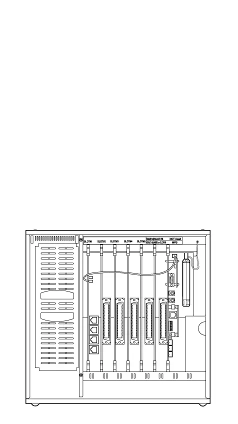
- ARIA-130 Key Telephone System

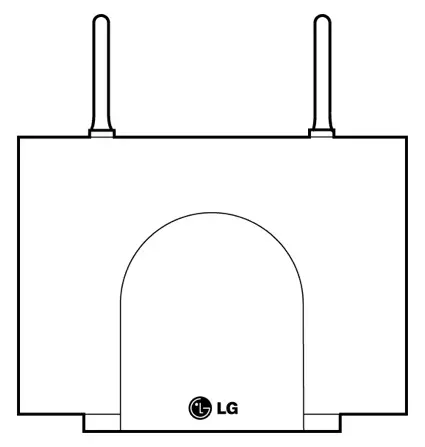
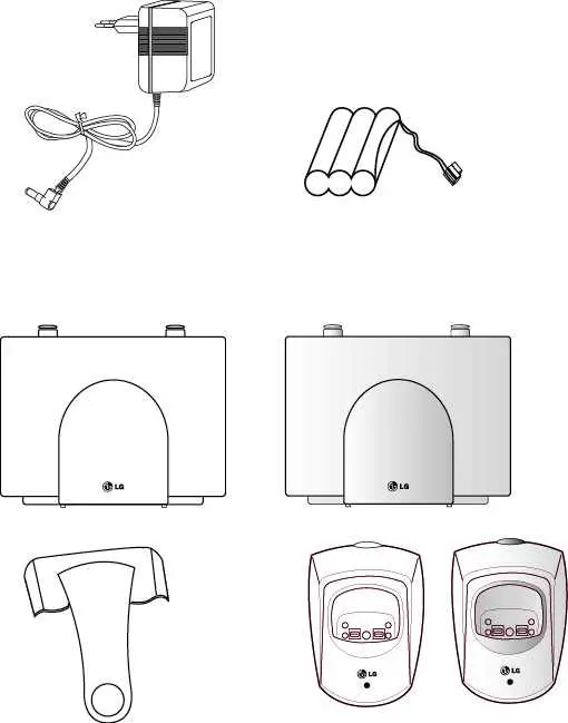
(b) Wireless Terminal (c) Charger(330-SSC) (d) Base station(GDC-330B)
(GDC-33Xh)

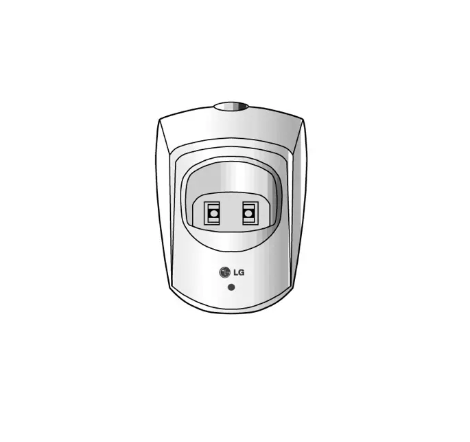
(e) Wireless Terminal(GDC-340H) (f) Charger(340-SSC)
Figure 5.1.1 Components of a ARIA-130 and ARIA-300 WOTS
A. ARIA-130 Digital Key Telephone System
The ARIA-130 Digital Key Telephone Systems are wired and full digital hybrid Key Telephone system, designed to meet the telecommunication needs for large and medium business offices respectively.
B. WTIB (Wireless Terminal Interface Board)
The WTIB provides standard interface between the ARIA-130 Digital Key Telephone system and DECT network, and can be optionally equipped with WTIU for expanding base stations. The system can accommodate
WTIBs which support up to 4 base stations each.
The WTIB should be plugged into slot 1 through slot 6, and should be installed at the same KSU in case of installing two WTIB.
WTIU (optional)
The WTIU is an optional board for cell expansion. If it is added to the WTIB, the system can support up to 4 base stations more.
The base station should be installed indoors and protected from surge because it is designed for indoor station.
The base station is used commonly in the GDK/LDK WOTS Series system. It has a RF(Radio Frequency) Module(transmitter and receiver) that handles communication with wireless terminals through the air link. It should be connected to ARIA-130 system via WTIB.
Each base station provides similar coverage for a particular area call as a cell, and supports five simultaneous calls (five traffic channels). However, since individual wireless terminals are not continuous in call, the system may support more than five wireless terminals:
In ARIA-130 system, Maximum 80 wireless terminals can be registered.
Base stations may be mounted on walls or desktops up to 600 meters away from the ARIA-130 WOTS using twisted 2-pair unshielded cable (0.5, AWG 24). They are remotely powered (DC 30 volts) by the WTIB.
The number of base stations used in a system depends on the area to be covered and the traffic density. The typical in-house coverage is a 40 meter radius. In practice the cell size may vary between 10 meters indoor in worst case situation and up to 200 meters outdoor in free space.
D. Wireless Terminal (GDC-33xH, 340H) : GDC-330H & GDC-335H & GDC-340H
It is designed for ease-to-use. The LCD shows various call-information, and the keypad has a 12-dial pad and additional keys that facilitate wireless terminal.
E. Single Slot Charger (330-SSC & 340-SSC)
The battery of a GDC-33xH is charged by a 330-SSC and The battery of a GDC-340H is charged by a 340-SSC.
How to Make Calls in the ARIA-130 WOTS
It is similar to other calls in a telephone system to make a call in ARIA-130 WOTS, except that every call to or from a wireless terminal involves establishing RF link to the wireless terminal through a base station. In an idle status, a wireless terminal scans a dummy bearer from base stations and locks to the base station with the strongest signal. The dummy bearer is similar to the control channel in a cellular telephone system. If the wireless terminal can not synchronize to a dummy bearer, it can not make a call.
System ID(PARK) is very important in the ARIA-130 WOTS calls. The WTIB should be assigned to a unique ARIA-130 WOTS ID(PARK). Installation Engineer should not use the other PARK ID as LGE assigns to the each system. Wireless terminals should be programmed with a system ID that matches a particular ARIA-130 WOTS before communicating with a base station in the system.
Calls to Wireless Terminal
- The WTIB receives a call from an extension of the system.
- To locate the called party, the WTIB sends a request containing the ID of the called wireless terminal to all base stations.
- The called wireless terminal responds to the base station onto which it is locked.
- The RF link is established. The call then proceeds like other calls in the office telephone system.
Initiated Call from a Wireless Terminal
- The wireless terminal locks onto a base station and initiates a RF link.
- The base station transmits call information to the WTIB. The call then proceeds like other calls in the office telephone system.
During a call, interaction occurs mainly between the wireless terminal and a WTIB. The wireless terminal accepts input at the keypad by user and sends the information to a WTIB via base station. The WTIB handles most of signaling functions and controls the display of wireless terminal.
Call termination involves releasing a voice channel and taking a wireless terminal into a standby status. When WTIB recognizes that a call has terminated, it sends a release message to a base station. The base station and wireless terminal are released.
In some cases, the base station should initiate call termination by sending a message to the WTIB. Loss of wireless terminal power and interference with the RF signal are examples of events that cause the base station to terminate a call abruptly.
ARIA-130 WOTS
The WTIB provides standard interface between the ARIA-130 Digital Key Telephone system and DECT network.
Fig 5.3.1 shows the layout of the WTIB of ARIA-130/ARIA-300.
WTIB
PCB
Modular jack
connector
SW1
JK1
JK2
JK3
JK4
ON
OFF
1 2 3 4
WTIB OF ARIA-130 WOTS
Default setting
LED 1 ~ 9
JK4
JK3
JK1
JK2
Figure 5.3.1 Layout of the ARIA-130/ARIA-300 WTIB
LED, Switch and Modular Connector
The 9 LEDs mounted on the ARIA-130/ARIA-300 WTIB provide diagnostic information for status of the board. Table 5.3.1 shows the meaning of various status of the LEDs.
| LED Number | Meaning (When it is lighted) |
| LED 1 | HDLC communication |
| LED 2 | Timer Interrupt operation |
| LED 3 | Subscription operation |
| LED 4 | Voice channel active |
| LED 5 | Inter-WTIB HDLC operation |
| LED 6 | Echo canceller operation |
| LED 7 | BMC PSCN operation |
| LED 8 | BMC Interrupt operation |
| LED 9 | Master/Slave operation |
Table 5.3.1 LEDs of the ARIA-130/ARIA-300 WTIB
The modular connector JK1, JK2, JK3, JK4(WTIB), JK1, JK2, JK3 and JK4(WTIU) are connected to base stations by twisted 2-pair unshielded cable. Table 5.3.2 shows the relation between modular connectors and associated cell numbers.
| Modular Connector Number | Cell Number |
| JK1(WTIB) | Cell 1 |
| JK2(WTIB) | Cell 2 |
| JK3(WTIB) | Cell 3 |
| JK4(WTIB) | Cell 4 |
| JK1(WTIU) | Cell 5 |
| JK2(WTIU) | Cell 6 |
| JK3(WTIU) | Cell 7 |
| JK4(WTIU) | Cell 8 |
Table 5.3.2 Relation between modular connector and cell number
| SW | On | Off | Description | Default |
| SW1-1 | Service | Normal | Reserved for test | OFF |
| SW1-2 | Enable Echo-can. | Disable Echo-can. | Echo-canceller control | ON |
| SW1-3 | Enable Watchdog | Disable Watchdog | Watchdog control | ON |
| SW1-4 | For emulator | Normal | S/W debugging | OFF |
Table 5.3.3 Switch and Jumper Setting Table
WTIB and WTIU Handling
The WTIB and WTIU contain digital circuitry which, while extremely reliable, can be damaged by exposure to excessive static electricity. When handling the WTIB and WTIU, a grounded wrist strap should be used to protect the board from static discharges with common sense for handling PCB. For example, do not place a PCB in the locations where heavy objects might fall and damage components.
Fig 5.3.2 shows a base station.

antenna
Figure 5.3.2 Base Station(GDC-330B)
Base stations may be mounted on wall or desktop up to 600 meters away from the WTIB using a twisted 2-pair unshielded cable(0.5). The system supports max. 24 base stations.
In typical office environments, each base station has a broadcast range of 50 meters and supports an area of 8,000 square meters. In settings where the absence of any obstruction provide perfect line of sight conditions between a base station and wireless terminal users and there are no atmospheric limitations, the range may increase to max.200 meters.
LEDs on the PCB of a base station provide diagnostic information for base station status.
| LED Number | Meaning | Normal State |
| LED 1 | PWR_ON | Steady _ON |
| LED 2 | REF_ON | Steady _ON |
| LED 3 | TX_ON | Blinking(like steady_on) |
| LED 4 | RX_ON | Blinking |
Table 5.3.4 LEDs on Base Station
Antenna Diversity
Spatial diversity at the base station is implemented by using two antennas. The antenna providing a best signal for each time slot is selected. This is performed on the basis of the RF power level and alternatively the quality information.
In DECT, the BER(Bit Error Ratio) is affected by multi-path propagation not only in terms of signal fading but in terms of time dispersion, which leads to ISI(Inter Symbol Interference). Antenna diversity reduces not only the fading probability but the effect of time dispersion.
Power Feeding
The base station is DC powered from the WTIB. Fig 5.3.3 shows the phantom power feeding circuit between a WTIB and a base station.

Figure 5.3.3 Phantom Power Feeding Circuit between WTIB and Base Station
Roaming
A base station intercommunicates with a user’s wireless terminal as long as the user stays in the service area of the base station. If the user moves out the area and into the service area of adjacent base station, the latter one will intercommunicate with the user’s wireless terminal.
So, in the whole area where the base stations of ARIA-130 WOTS cover, users can make or receive a call without any problem. It is called ‘Roaming’
This system supports roaming function
Hand-over
ARIA-130 WOTS supports hand-over which is essential function to accomplish a call without cutting off while wireless terminal is moving from local service area (or cell) to adjacent area (or cell).
Digital Voice Quality
The ARIA-130 WOTS uses advanced digital technology to provide high sound quality as almost equal to fixed line telephones. Speech coding uses 32kbps ADPCM(Adaptive Differential Pulse Code Modulation) conforming to CCITT recommendation G.721.
Multiple Simultaneous Users
The ARIA-130 WOTS accommodates 64 multiple users in simultaneous conversation with no degradation in performance.
C. Wireless Terminal (GDC-33xH, 340H) : GDC-330H & GDC-335H & GDC-340H

Ring LED
ON/OFF
FLASH/
CLEAR
Ear/Mic Jack
SPEED
TRANSFER
POWER &
CALL BACK
Antenna
Display Area
HOLD
Standard
Dial Pad
FUNCTION
REDIAL
Volume UP
Ear piece
Volume DOWN
C-Mic
Belt Clip
Ear piece
Display Area
FLASH/CLEAR
Ear/Mic Jack
ON/OFF
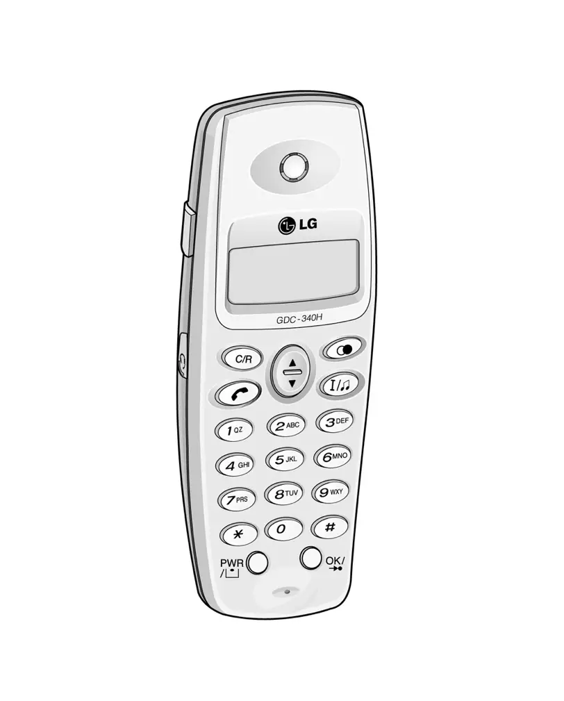
POWER &
CALL BACK
UP/DOWN/MENU
REDIAL/
PAUSE
Standard
Dial Pad
OK/SPEED/
FUNCTION
C-Mic
TRANSFER/HOLD
(a) GDC-33xH (b) GDC-340H
Figure 5.3.4 Wireless Terminal
The wireless terminal is designed for ease-of-use at the desks of users or moving throughout a facility.
- It is small and light for ease-of-use.
- The LCD displays call information and the status of terminal.
- The keypad contains specially labeled keys assisting users to make calls and operate telephone features.
Subscription
The wireless terminals associate unique identities, to prevent unauthorized use of the PSTN line. See the User Guide of the GDC-33xH and GDC-340H for the subscription of wireless terminals.
LCD Display
The GDC-33xH has a three-line display (6 icons & 20 characters) for alphanumeric information and the GDC-340H has a three-line display (8 icons & 24 characters) for alphanumeric information.


(a) GDC-33xH (b) GDC-340H
Figure 5.3.5 The LCD Display
Security
The wireless terminal ciphers voice information before transmitting it. It ensures that the conversations are private and inaccessible to electronic eavesdropping.
Ringing
There are various types of ring signal in the wireless terminal and users can select the ring signal and control the volume of ring signal. Seven volume levels are available in GDC-335xH and four volume levels are available in GDC-340H.
Key Pad Tone
A beep is heard when the wireless terminals recognize a dial input from dial pad.
Low Battery Alarm
When the battery is discharged to low battery state, the low battery message is displayed in the display LCD of the wireless terminal (except GDC-340H) and warning tone is heard (both GDC-33xH and GDC-340H).
Removable Battery Pack
The GDC-33xH has one type of battery pack (330-SBP, 600mAh). It is standard battery pack.
The GDC-340H has standard rechargeable battery (1.2V rechargeable NiMH AAA size 2 cell).
Antenna
The antenna of the GDC-33xH is an wire and non-retractable antenna. Do not extract it. If you try to pull it out, it may be destroyed. The antenna of the GDC-340H is embedded.
Holes of Top and Bottom Side
There are two holes in the top and bottom side of a GDC-33xH. The holes are special purpose and are covered with covers. Do not take off these covers.
Charger (330-SSC & 340-SSC)
The GDC-33xH comes with a charger that accommodates GDC-33xH and one type of battery pack. And the GDC-340H comes with a charger that accommodates GDC-340H and standard rechargeable battery. The 330-SSC & 340-SSC is supplied with the adapter (330-HAP). 330-HAP adapter is used for the charger, 330-SSC & 340-SSC. There are two types of adapter.
It is dependent on country adaptation.
Type -Ⅰ
- Input : Only AC 230V ~ 50Hz 50mA
- Output : DC 12V, 200mA 2.4VA
Type -Ⅱ
- Input : Both AC 220V and 110V ~ 50/60Hz
- Output : DC 12V, 200mA
LED (red) on the charger indicates that charging is in progress.
In the GDC-33xH, when a battery is almost consumed during a call or in an idle state, warning tone will be heard more 3 times in every 20 second with “LOW BATT.” message on the LCD, and a low-battery icon ( 

The battery inside of GDC-33xH and GDC-340H is Nickel Metal Hydride (NI-MH) and can be charged any time. To increase the lifetime of the battery, use the wireless terminal without charging until the battery alarm is heard.
System Configuration
The ARIA-130 WOTS is used in single cell or multi-cell (maximum 16 cells).
Before Installation
Followings are the factors that affect the quality of service for the ARIA-130 WOTS.
Location of base station
Number of wireless terminal users within a base station range
Obstructions between base station and wireless terminal
Coverage area
Desired quality of service
The purpose of this section is to provide you with information and explain tasks that you should complete to ensure the best operation of the system.
The following procedure is very helpful to check the coverage region and install the base station:
- Site survey (see the sub-clause A)
- Judge where to place bases on plan drawing (see the sub-clause B).
- For each base, check coverage tool (see the sub-clause D and CRS Tool Manual).
- Plot limit line for each base station.
- Check for shadow area.
- Adjust base position for shadow area or add base if not possible.
- Consider traffic 5 calls per cell add to plan.
- Install the base station (see the 5.4.2 Hardware Installation).
- Check with 33xH GAP handset using RSSI (possible in GDC-33xH only, displays only one base station at a time, limit is -80dbm: see the sub-clause E)
- Walk with 2 handsets, monitor for voice quality and ‘OUT OF RANGE’ message.
- If it is OK, finish it.
- Get building blue prints.
- Check building material and thickness.
Consider the general construction materials used in walls, doors between multi-story buildings and window coatings and coverings. Consider any large metal objects, such as equipments, doors, and fluorescent lampshades too.
In general, signals are attenuated to some low degrees when they pass through any barrier, however, some materials such as metal attenuate much degree.
Note
- Consider high traffic areas, such as conference rooms, cafeterias, and manufacturing floors.
- Consider office locations and number of wireless terminal users within the site.
B. Base Station Broadcast Range and Location
- Base Station Requirements
To determine the number of base station in a system, you should consider base station broadcast range.
- Base Station Range
In a typical office environment, each base station has a broadcast range of 50 meters and supports an area of 8,000 square meters, but a broadcast range depends entirely upon office environment. Where the absence of any obstruction provides perfect line of sight conditions between the base station and wireless terminal user. If there is no atmospheric disturbance the range may increase to 200 meters.
The following base station broadcast ranges can be used as a rough guide to plan the base station positions:
- In line of sight, the base station has a range of up to 200m(open area).
- In hall, the base station has a range of 40-70m.
- In buildings, the base station has a range of about 25-40m. It assumes that walls are made of light brick, plasterboard or wallboard with metal frames. Normal electrical wiring, central heating pipes, office furniture and desktop computer equipment have no significant effect.
r
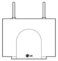
r = Typical office environment : up tp 50 meters
r = Line of sight : up to 200 meters
Base Station
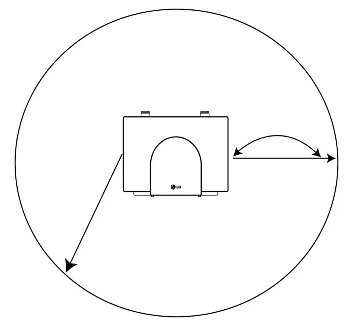
Figure 5.4.1 Base Station Service Area
The characteristic antenna field pattern is a torus(doughnut) centered on the antenna.
- Base Station Location on the Plan Drawing
Determine the location of the base station on the plan drawing according to the previous information based on the base station broadcast range.
Once you have completed the steps described in Site Survey on sub-clause A and determined the number of base stations you need, you should determine where to install the base stations for optimum coverage and operation of the ARIA-130 WOTS.
C. Traffic Guidelines
Each base station supports five simultaneous calls, but because all users are not simultaneously in call statistically, a base station can support a greater number of wireless terminal users in practice.
ARIA-100 WOTS
| Number of Cell (Base station) | Recommended Number of Registered Wireless Terminals | Number of maximum Simultaneous Wireless Conversation |
| 1 | 8~80 | 5 |
| 2 | 10 | |
| 3 | 15 | |
| 4 | 20 | |
| : | : | |
| : | : | |
| 15 | 64 | |
| 16 | 64 |
Table 5.4.1 Suitable Wireless Terminal Number according to Base Station Number
D. CRS(Cell-Coverage Region Survey) Tool
For the easy installation, LGE prepares the portable tools which consist of the base station and the wireless terminal.
This section provides general guidelines for determining location of base station in the site.
For more information, see the CRS Tool Manual.
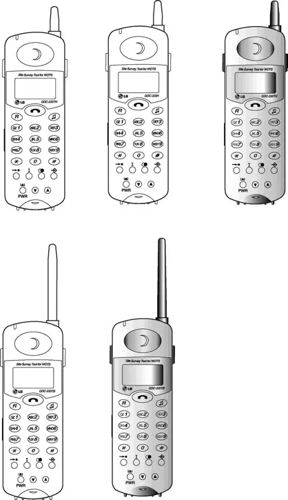
CRS FT
DECT air interface

FT : Fixed radio Termination
PT : Portable radio Termination
CRS PT
Figure 5.4.2 Installation Configuration using the CRS Tool
General Guidelines
- Place the base stations where to maximize direct line of sight between wireless terminals and base station antennas. Mounting base stations as high as possible will satisfy this guideline.
- Place the base stations where to minimize obstructions near antennas. If you mount a base station on a wall, place it higher than the average tall person and do not mount it near doors that could temporarily obstruct antennas when the door is opened.
- Antennas on wall-mounted base stations should be parallel to the wall.
- Centralize base stations within the area that you intend to cover.
- When rule 1 cannot be observed, place base stations so that signals begin their paths with a clear line of sight and then bend at the end of their travel to a receiving antenna. It limits the affect of signal fading.
- To minimize blocking in high traffic area, install the base stations required to meet the estimated traffic demand. When multiple base stations are needed in the same location, you may mount base stations as close as one meter apart (to avoid one obstruction to the other according to the rule 2).
- The base stations are designed to use frequencies that are not in use yet, so there is no problem of interference between base stations that are mounted near each other.
- In multi-story environments, it is the best to plan coverage for each floor separately. However, because RF signals can travel between floors, a single base station could support multiple floors as long as base station broadcast area, traffic requirements, and other general guidelines are kept in mind.
Usually, DECT wave is attenuated by reflection indoors. In order to minimize attenuation, when you install a base station on the wall, give at least three-wave-length intervals. The intervals should be at least 45 centimeters because the wavelength is 15 centimeters at DECT frequency.
The best communication environment is when a base station and a user are in the same height. In office environment, however, it is desirable to consider office furniture to minimize reflection, diffraction and scattering of DECT wave when you set the position of a base station.
The appropriate position for a base station is where 1.8 meter above from the floor and 0.5 meter below from the ceiling. The top of iron office furniture such as a cabinet or a desk is not a good position. Keep away from electronic equipment such as a copy machine, a printer or a computer. And the lower wall of a corridor where many people pass by, corner of a wall, and narrow indoors also should be avoided.
E. RSSI Monitoring(Possible in GDC-33xH only)
This function helps that the dealer can install base stations without CR instrument. The RSSI (Received Signal Strength Indicator) level of a base station of which the wireless terminal is locked is displayed as dBm value on the LCD (The limit is -80dbm.). This value is updated periodically.
- Press FUNCTION(
) button.
- Press .
- To enter Technician menu, press PIN code (‘L’,’G’,’G’,’A’,’P’ = ‘5’,’4’,’4’,’2’,’7’).
- Press FUNCTION(
) button.
- Technician Main Menu is displayed on the LCD.
Press (Or set ‘<’ mark to ‘4 ShowRSS’ to press UP(
) button or DOWN(
) button and press FUNCTION(
) button.).
(The RSSI value is displayed on the LCD and the value is updated periodically.)
- Press FLASH button to return to Main Menu.
Hardware Installation
Aria-100 WOTS Equipment
- WTIB, WTIU (optional)
- Base stations (GDC-330B) , Connecting block and line cord, Ferrite core
- Wireless terminals (GDC-33xH, GDC-340H), Single-slot charger (330-SSC, 340-SSC), Battery (330-SBP, standard rechargeable battery AAA size) and Adapter (330-HAP)
Fig 5.4.3 show the packing components of the WTIB and WTIU.
GDC-330B, GDC-33xH, GDC-340H, Single-slot Charger(330-SSC, 340-SSC), and Adapter(330-HAP) are shown at Fig 5.4.4 and Fig 5.4.5 in each.
Figure 5.4.3.a Packing Components of WTIB
CN4
KM684000BLG-7L
DBID II
U18
U10
DBID II
DBID II
BMC
PCD5043
KM684000BLG-7L
100
10V
CB2MRX
65311
CB2MRX
65311
CB2MRX
65311
CB2MRX
65311
100
10V
100
10V
100
10V
U4
DBSIB
U4
DBSIB
DSP
TMS320VC5402
DSP
TMS320VC5402
U7
DSP
TMS320VC5402
16.384
100
10V
KJE
10MHz
TCXO
13.824MHz
KJE
BMC
PCD5043
BMC
PCD5043
BMC
PCD5043
LEVEL
ONE
LXT318PE
LEVEL
ONE
LXT318PE
LEVEL
ONE
LXT318PE
LEVEL
ONE
LXT318PE
33
10V
33
10V
ROM1
27C020
ROM2
27C020
ATMEL
AT28C64
ARIA-130 WTIB ISS.: Rev.:
ON
1
2
3
4
JK1
JK2
JK3
JK4
U11
U12
U19
SW2
SW1
CN1
CN2
LD1
LD9
CN3
U1
U2
U14
U15
U16
U17
MC68302

Figure 5.4.3.b Packing Components of WTIU
Base station

Base Station(GDC-330B)
Figure 5.4.4 Packing Components of GDC-330B
Note: Place the Ferrite Core close to a System(WTIB) side as close as it can be.
Wireless Terminal Packing


Belt Clip 330-SBP


GDC-33xH
330-SSC 330-HAP
(a) GDC-33xH
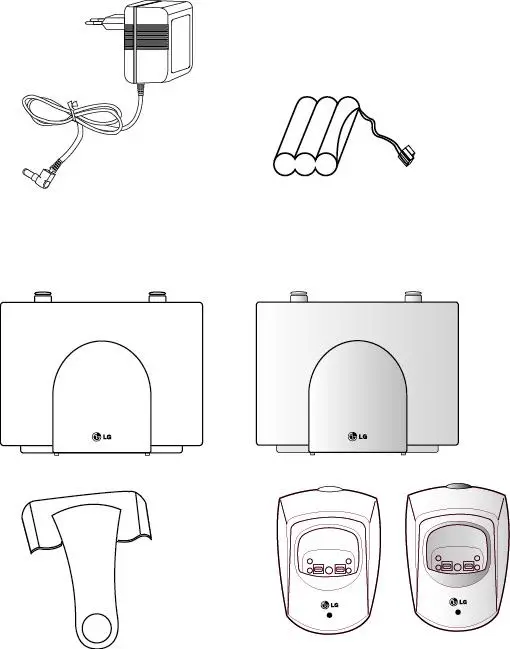

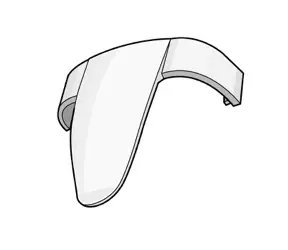
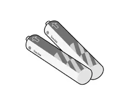
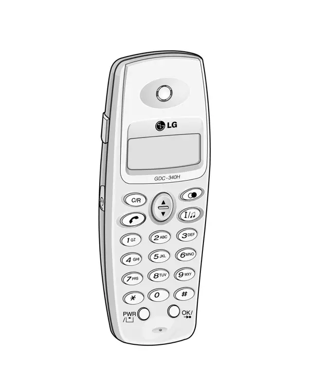
Belt Clip
Rechargeable Battery
GDC-340H 340-SSC 330-HAP
(b) GDC-340H
Figure 5.4.5 Packing Components
WTIB/WTIU Installation
In ARIA-130 Digital Key Telephone System, WTIB is a base station interface board.
ARIA-130 system can have two WTIB and WTIU.
If the WTIB is installed in a power-on system, the system and/or WTIB can be damaged. Thus after system power is off, the WTIB should be plugged in/out to/from the system.
If the WTIB is re-plugged into a system after extraction, the WTIB should be plugged into the original slot. Otherwise programmed data do not match the station numbers.
The WTIB can be installed in slot 1 through slot 6 of KSU, and should be installed at the same KSU in case of installing more than one WTIB.
The WTIB can have a WTIU daughter board. Fig 5.4.6 shows the wiring diagram of the 
Figure 5.4.6 Wiring Diagram of WTIB
Base Station Installation
Before mounting base station permanently, you should determine a suitable location providing the best coverage. Use the last sheet of this manual for mounting template to drill pilot holes in the wall.
The weight of a base station is light as approx. 460g, so it can be mounted on a masonry or dry-wall surface, wooden wall, or partition wall. The distance between mounting holes is 121mm as shown in Fig 5.4.7. The base station is mounted with 1 1/2 inch or longer screws. Drill pilot holes in the two locations, insert the screws and tighten leaving about 3mm gap between the wall and screw head. Mount the base station on the screws and tighten the screws securely.

Figure 5.4.7 Wall Mounting of Base Station (without wedge)
Before mounting base station permanently, you should determine locations that provide the best coverage. The wall mounting procedure of a base station is as follows:
- Drill two 3.5mm holes in a fixed wall. To properly position the holes, you can measure the tags on the base station or mark the surface through the tag eyelets while holding the base station in place.
- Insert anchors into the drilled holes. Then insert screws in the anchors, leaving a 3mm gap between the wall and screw head.
- Mount the base station eyelets on the screws.
Mounting Base Station – 2 (Using Wedge)
Installing the Base Station using the wedge,
- Determine at first the location on wall where the wedge prepared for mounting the base station is to be fixed.
- The wedge should be settled by using two screws on the wall.
- And insert the base station pulling down into the wedge.
screw
Base Station
Wedge
wall
Insert the GDC-330B
pulling down into the wedge
Figure 5.4.8 Wall Mounting of Base Station using Wedge
WTIB-Base Station Cabling
The Base Station is connected to the WTIB by a 1.152 Mbit/s transmission unshielded cable. The following rules should be obeyed:
The cable for connecting WTIB with a base station should be a twisted pair unshielded cable.
Shielded cable can be used if it can be interfered by others like AC power cable with high voltage. But it can shorten the cable length between WTIB and Base Station because its high capacitive component can degrade the shape of data. So we recommend to use unshielded cable.
The cable for connecting the WTIB with a base station shall be separately cabled. This connection shall be cabled separate to the building cabling using twisted 2-pair CAT5 unshielded cabling.
The following characteristics should be observed for all cables:
DC resistance: The resistance of a conductor should not exceed 73.4 ohm per km for a temperature of 20 degree.
Attenuation: The attenuation of any pair should not exceed 17 dB per km on condition of a temperature of 20 degree and frequency of 1 MHz.
Characteristic impedance: Characteristic impedance should remain in the range of 100 ohm _ 15% for a frequency of 1 MHz.
Crosstalk: The total crosstalk of any pair (Far-end and Near-end crosstalk), measured over a line length of 1800 metres should not exceed 40 mV.
Ferrite Core Installation
Ferrite core is provided in the package of Base station for EMI. Ferrite core should be installed when WTIB is installed in the key telephone system. One Ferrite core in the package of base station is for line cord between base station and each port of WTIB & WTIU.

Figure 5.4.9 Connecting Base Station with WTIB
Wireless Terminal Installation
To install a GDC-33xH(GAP), GDC-340H(GAP), simply take out the handset and batteries (330-SBP, rechargeable battery), charger(330-SSC, 340-SSC) and AC/DC adapter(330-HAP) from the package and assemble it. Before using the GDC-33xH and GDC-340H, you should recharge the battery fully.
After inserting a battery, press the power button of GDC-33xH (GAP) and GDC-340H. Fig 5.4.10 shows the initial LCD. The two icons in the left upside of the LCD are blinking until the GDC-33xH is subscribed.
(In GDC-340H, these icons are not displayed until the GDC-340H is subscribed)


(a)GDC-33xH(GAP) (b) GDC-340H
Figure 5.4.10 LCD Message of unsubscribed
Before using the GDC-33xH(GAP) and GDC-340H(GAP), it should be subscribed. Fig 5.4.11 shows the LCD message of the subscribed GDC-33xH(GAP) and GDC-340H(GAP).


(a)GDC-33xH(GAP) (b) GDC-340H
Fig 5.4.11 LCD Message of Subscribed
Refer to the 5.4.3 User subscription/de-subscription of this manual and the User Guide of the GDC –33xH and GDC-340H for the detail information.
User subscription/desubscription
A. System ID
Description
System ID is given to the ARIA-130 system attached the wireless GAP terminal for identification. System ID, which is PARK(Potable Access Rights Key), is written on MPB.
PARK: 31100013411741
Authentication Code as well as system ID should be entered at only attendant station, before you begin to subscribe wireless terminal (GAP) to ARIA-130 system.
Operation
- In case of confirming system ID
- At attendant station
| [Trans/Pgm] | + | 0 # | + | Flex. Button 4 |
- If you press the [Trans/Pgm] button, [Trans/Pgm] LED will flash(60 IPM Flash) and [On/Off] LED will be turned on. Then you can enter then user program mode.
- Press ‘ 0, # ’.
- Press Flexible Button 4.
- Current PARK code will be displayed in LCD.
- In case of entering system ID
- At attendant station
| [Trans/Pgm] | + | 0 # | + | Flex. Button 6 | + | System ID(PARK) | + | [Hold/Save] |
CAUTION: Normally you should not change the system ID. If you should change it, please contact LG or local dealer in your country.
- If you press the [Trans/Pgm] button, [Trans/Pgm] LED will flash(60 IPM Flash) and [On/Off] LED will be turned on. Then you can enter then user program mode.
- Press ‘ 0, # ’.
- Press Flexible Button 6.
- Enter the system ID(PARK code).
- After entering the PARK code, press [Hold/Save] button. Then you can hear confirm tone.
The key sequence of the PARK : LLP__________PC
LL : Two digits decimal representation of PARK length (Bit count)
P______P : 11 octal digits representation of PARK
C : Check digit (It is calculated as the sum of each digit in the input stream multiplied by its position in the input stream , modulo 11; if the result is 10, this is represented by the “*”.)
Conditions
- You must program for system ID when you install the system.
- If you program system ID, all data that were related to wireless features will be erased.
- The initial PARK value is 00000000000000. So the value will be display in LCD at first
Description
Authentication Code is entered at only attendant station before you begin to subscribe wireless terminal(GAP) to ARIA-130.
Operation
- In case of confirming AC code
- At attendant station
| [Trans/Pgm] | + | 0 # | + | Flex. Button 3 |
- If you press the [Trans/Pgm] button, [Trans/Pgm] LED will flash(60 IPM Flash) and [On/Off] LED will be turned on. Then you can enter then user program mode.
- Press ‘ 0, # ’.
- Press Flexible Button 3.
- Current AC code will be displayed in LCD.
- In case of entering AC code
- At attendant station
| [Trans/Pgm] | + | 0 # | + | Flex. Button 3 | + | AC Code(Max 8 Digits) | + | [Hold/Save] |
The key sequence of the AC code : D______D
D_______D : Up to 8 digits decimal representation.
- If you press the [Trans/Pgm] button, [Trans/Pgm] LED will flash(60 IPM Flash) and [On/Off] LED will be turned on. Then you can enter then user program mode.
- Press ‘ 0, # ’.
- Press Flexible Button 3.
- Enter the AC code.
- If you press the [Hold/Pgm] button, you will be heard confirm tone.
Condition
- AC code is must be programmed for user subscription.
- AC code must be programmed one time after system was installed. If you change AC code under system operation, it may not operate properly.
(Ex : Subscribed terminal may not receive the incoming call or not make an outgoing call)
- If PARK value are changed, you must enter the AC code again.
- The initial AC code is 000000.
- AC code change will not affect the system operation except subscribing new wireless terminal.
Description
This procedure is for subscribing the wireless terminal to ARIA-130 system.
Operation
- Attendant station
| [Trans/Pgm] | + | 0 # | + | Flex. Button 1 | + | Station Number + | Phone Type + | [Hold/Save] |
- If you press the [Trans/Pgm] button, [Trans/Pgm] LED will flash(60 IPM Flash) and [On/Off] LED will be turned on. Then you can enter then user program mode.
- Press ‘ 0, # ’.
- Press Flexible Button 1.
- Enter the station number.
- Enter the phone type (LG-GAP for ARIA-130 system or standard GAP for any other system). In case of LG-GAP terminal, press [1] button. Otherwise press [2] button.
* Note : In case of GDC-340H, If MPB version is 1.0Ba above, press [3] button.
- Press [Hold/Save] button and confirmation tone is heard.
- If succeeded, the attendant station will display “ SUBSCRIBED: SUCCESS” on the LCD display.
- If failed(ether at attendant or at wireless terminal), repeat ③ ~ ⑥ steps of the attendant.
* Note : Station range of wireless terminal
How to confirm station range assigned to wireless terminal.
At attendant station,
| [Trans/Pgm] | + | 0 # | + Flex. Button 9 |
- At the wireless terminal(GDC-33xH)
| [Function] | + | 0 | + | PARK code | + | [Redial] | + AC code | + [Redial] | + FT No. + | [Function] |
- Press [Function(
)] button.
- Press 0.
- Enter system ID(PARK ).
- Press [Redial (
)] button.
- Enter AC code.
- Press [Redial (
)] button.
- ‘1’,’2’,’3’,’4’ or ‘_’ are displayed on the LCD. A number means FT number that it is not occupied yet. The under-bar means the wireless terminal is already subscribed to the system. Therefore, the number of ‘_’ means the number of subscribed system. If 4 under-bar are displayed on the LCD, that means no subscription is allowed any more. Enter FT number by pressing numeric key if any number exists. After selecting, it is possible to re-select FT number by pressing [Flash(R)] button to cancel selection.
- Press [Function(
)] button.
- Success or failure of the subscription is notified with confirmation tone to the attendant and the wireless terminal.
- If succeeded, the wireless terminal goes to an idle state and its station number is displayed.
- If failed, repeat ③~⑥ steps of the attendant and ①~⑧ steps of wireless terminal.
The key sequence of the PARK : LLP__________PC
LL : Two digits decimal representation of PARK length (Bit count)
P______P : 11 octal digits representation of PARK
C : Check digit (It is calculated as the sum of each digit in the input stream multiplied by its Position in the input stream, modulo 11; if the result is 10, this is represented by the “*”.)
The key sequence of the AC code : D_____D
D_____D : AC value : Up to 8 digits decimal representation.
FTID : 1 ~ 4
- At the wireless terminal (GDC-340H : Auto subscription is provided only)
| [MEMU/UP/DOWN] + | 5 1 + | select Base No + | [OK] + | AC code | + | [OK] + |
| Display SEARCHING + | Display PARK(last 12Digit) + | [OK] |
① Press MENU (UP or DOWN) button.
 ② Press .
 ③ Press .
④ Select base number (1~4) using UP or DOWN button and press OK button.
⑤ Enter AC code (up to 8 digits decimal representation) and press OK button
⑥ The wireless terminal tries to search for the register system and ‘SEARCHING’ is displayed on the LCD. After searching the register system, PARK(last 12digits) value is displayed on the LCD.
⑦ If the PARK value displayed is right, press OK button. If the PARK value displayed isn’t right press UP or DOWN button. And then the wireless terminal retries to search for the register system and ‘SEARCHING’ is displayed again.
⑧ Success or failure of the subscription is notified with confirmation tone to the attendant and the wireless terminal.
⑨ If succeeded in subscription, the wireless terminal goes to an idle state and its station number is displayed.
⑩ If failed, repeat 3) ~ 6) steps of the attendant and 1) ~ 7) steps of wireless terminal.
Condition
- Wireless terminal must be subscribed to system for normal service.
- Only attendant can subscribe the wireless terminals(GAP).
- Attendant can subscribe another wireless terminal after one subscribing procedure.
- If attendant want to subscribe wireless terminal that was subscribed already, it will be heard error tone.
Description
This procedure makes a wireless terminal loose access right to the ARIA-130 system. To de-subscribe the wireless terminal, it should be in an idle state.
Operation
- Attendant station
| [Trans/Pgm] | + | 0 # | + | Flex. Button 2 | + | Station Number + | [Hold/Save] |
- If you press the [Trans/Pgm] button, [Trans/Pgm] LED will flash(60 IPM Flash) and [On/Off] LED will be turned on. Then you can enter then user program mode.
- Press ‘ 0, # ’.
- Press Flexible Button 2.
- Enter the station number.
- Press [Hold/Save] button and confirmation tone is heard.
- Success or failure of the subscription is notified with confirmation tone to the attendant and the wireless terminal.
- In case of the GDC-33xH, If succeeded in de-subscription, the below LCD message will be displayed. Power-off the wireless terminal

- In case of the GDC-340H, If succeeded in de-subscription, GDC-340H tries to synchronize to next registered system. If there isn’t next registered system, GDC-340H displays “UNREGISTERED” on LCD.
Condition
- Only attendant can de-subscribe wireless terminal.
- Attendant can de-subscribe wireless terminals those were subscribed already.(If attendant try to de-subscribe un-subscribed wireless terminal, it will be heard error tone.
- Attendant can de-subscribe another wireless terminal after one de-subscribing procedure.
- Attendant can do de-subscribing procedure only when wireless terminal is at the idle state.
* Notes : If you want to do de-subscribe procedure at wireless terminal and attendant station independently, Follow the procedure that described below.
- At attendant station
- To erase all data those were subscribed.
| [Trans/Pgm] | + | 0 # | + Flex. Button 7 | + | Password(147*) + | [Hold/Save] |
- Press the [Trans/Pgm] button, [Trans/Pgm] LED will flash(60 IPM Flash) and [On/Off] LED will be turned on. Then you can enter then user program mode.
- Press ‘ 0, # ’.
- Press flexible button 7.
- Enter password.
- Press [Hold/Save], you will be heard confirmation tone.
- To erase a special wireless terminal
| [Trans/Pgm] | + | 0 # | + Flex. Button 8 | + Station Number + | [Hold/Save] |
- Press the [Trans/Pgm] button, [Trans/Pgm] LED will flash(60 IPM Flash) and [On/Off] LED will be turned on. Then you can enter then user program mode.
- Press ‘ 0, # ’ .
- Press flexible 8.
- Dial station number that you want to de-subscribe.
- Press [Hold/Save], you will be heard confirmation tone.
Condition
- Wireless terminal must be de-subscribed to system for normal service.
- Only attendant can de-subscribe the wireless terminals.
- Attendant can de-subscribe another wireless terminal after one subscribing procedure.
- If attendant want to de-subscribe wireless terminal that was subscribed already, it will be heard error tone.
- At the wireless terminal (GDC-33xH)
| [Function] | + | 9 | + | 0000 | + | [Function] | + | Select Park number + | [Function] |
- Press [Function(
)] button.
- Press 9.
- Enter User PIN number “0000”.
- Press [Function(
)] button.
- Select PARK number with UP(
), DOWN(
) key.
- Press [Function(
)] button.
- If the below LCD message is displayed. Power-off the wireless terminal.

- At the wireless terminal (GDC-340H)
| [MENU(UP or DOWN)] | + 5 + 2 + PIN Code + | [OK] + |  or or  (To select FP#) + (To select FP#) + | [OK] |
- Press MENU(UP or DOWN) button.
 Press . (Or set ‘’ mark to ‘5 System’ by pressing UP(
 ) button or DOWN(
) button and press OK button).
 Press . (Or set ‘’ mark to ‘5 UnRegister’ by pressing UP(
 ) button or DOWN(
) button and press OK button).
- Enter PIN code(0,0,0,0) If a user has changed PIN code before, the changed one should be entered.
- Press OK button.
- If necessary, press UP(
) button or DOWN(
) button to select FT number which is desubscribed. If the desubscribed FT number is displayed on the second line of LCD, stop pressing UP(
) button or DOWN(
) button.
- Press OK button.
 Press . (Or set ‘’ mark to ‘5 System’ by pressing UP(
  Press . (Or set ‘’ mark to ‘5 UnRegister’ by pressing UP(
 * Note:
- GDC-340H tries to synchronize to next registered system.
- If there isn’t next registered system, handset displays “UNREGISTERED” on LCD.
Summary of DECT Installation
Check and prepare the equipment.
- Install a ARIA-130 Digital Key Telephone System.
- Install the WTIB (and WTIU).
- Determine location of base stations.
- Install base stations.
- Connect the WTIB with base stations by twisted 2-pair unshielded cables.
- Install the ferrite cores on signal wires of base station line cord.
- Slot Assignments & Determination of the number of able to register wireless terminals.
- Reset the ARIA-130 System.
- Program of the PARK at the attendant station.
- Register wireless terminal.
- Make an initial call.
Aria-130 DECT – A Quick Programming Guide
Determine the PARK number.
The Portable Access Rights Key number can be found on a label on the MPB. e.g. 31100013505703.
If the PARK No has already been entered into the system, you can read it from the attendant position, follow this procedure: –
At the attendant: –
- Press [TRANS/PGM]
- Dial 0#
- Press flex button 4
- The 14 digit PARK number will be displayed.
To enter the PARK No into the system, (this will Initialise the WTIB).
At the Attendant: –
- Press [TRANS/PGM]
- Dial 0#
- Press flex button 6
- Enter the PARK Number
- Press [HOLD/SAVE]
- Hear confirmation tone.
Enter AC (Authentication code).
At the Attendant: –
- Press [TRANS/PGM]
- Dial 0#
- Press flex button 3
- Dial the AC code (up to eight digits) e.g. 12345678.
- Press [HOLD/SAVE]
To Subscribe.
At the Attendant: –
- Press [TRANS/PGM]
- Dial 0#
- Press flex button 1
- Dial the Station number.
- Dial the phone type. (e.g. 1 = GDC-335H; 3 = GDC-34xH)
- Press [HOLD/SAVE]
At the GDC-335H wireless terminal: –
| At the GDC-340H wireless terminal: –
|
| At the GDC 345h wireless terminal you have a choice of two subscription modes:- MANUAL:-
| AUTO:-
|
To De-Subscribe a single user from the attendant.
At the Attendant: –
- Press [TRANS/PGM]
- Dial 0#
- Press flex button 2
- Dial the station number
- Press [HOLD/SAVE
To enter the Technicians Menu from the GDC-335H Wireless Terminal
- Press function key
- Dial *
- Dial PIN – LGGAP (= 54427) ( FAC code)
- Press function key
- The technician menu is displayed.
- Scroll with up/down arrows
- Select with function
- Go back with “R”
Technicians Menu of the GDC-335 H Wireless Terminal:-
- Version. Displays software version.
- Reset. Clear programmed data, initialise to default.
- IPEI. International Portable Equipment Identity.
- ShowRSS. Receive Strength Indicator.
- Test. LED, (led indicator when handset is ringing). BUZZ, (Test handset ring). LCD, (Test/verify LCD display). KEY, Test individual buttons/keys, will display button pressed).
To enter the Technicians Menu on the GDC-345H Wireless Terminal:-
- Press MENU up or down key
- Dial *
- Dial PIN – LGGAP (= 54427) ( FAC code)
- Press OK key
- The technician menu is displayed.
- Scroll with up/down arrows
- Select with OK key
- Go back with C/R key
Technicians Menu of the GDC-345H Wireless Terminal:-
- Version. Displays software version.
- Reset. Clear programmed data, initialise to default.
- IPEI. International Portable Equipment Identity.
- Test. – 1. Buzzer Tests Ring function. – 2. LCD Tests all segments of LCD. – 3. Keypad Enables manual button testing.
Aria Digital Key Telephone System Aria-130 User Manual – Download


