![]() User’s Guide to the
User’s Guide to the
Universal WorkBench™
Project Development Kit (PDK) from Phase Dock®
2022/05/15 Guide to Using the Universal WorkBench™ Project Development Kit from Phase Dock
Phase Dock 1007 WorkBench Starter Project Development Kit
| Quantity | Item | Purpose |
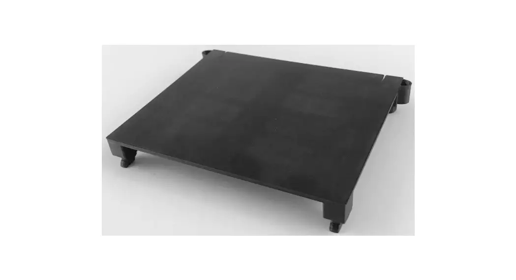
| 1 | 1007 Base. acrylic | Prototype, manage electronics, and transport |
| 4 | 2×3 Click | Attach to Base. Use to mount any electronics of appropriate size. See Assembly Guide & Mounting Instructions below. |
| 1 | 1×3 Click | |
| 1 | Slide, Arduino UNO | Mount Arduino UNO or MEGA; or any board that shares the Arduino hole-mounting pattern |
| 1 | Slide, Raspberry Pi 2/3 | Mount Raspberry Pi 2/3/4; or any board that shares the RasPi 2/3/4 hole-mounting pattern |
| 1 | Slide, Feather/Particle | Mount Adafruit Feather 32u4 Basic, or Particle Argon, Boron, or Xenon; this Slide also accepts the Adafruit FeatherWing Terminal Block Breakout kit; or any board that shares the Feather mounting standard |
| 1 | Hardware Packet | |
| 12 + 1 extra | M2.5 hex nuts | Click/Slide assembly. |
| 12 + 1 extra | M3.0 hex nuts | Click/Slide assembly |
| 1 | M2.5 x 20 screw | Insertion tool for Click/Slide assembly |
| 12 + 1 extra | M2.5 x 8mm machine screws | Attach electronics to Click/Slide assemblies. |
| 4 | Nylon m/f standoffs (black) | Use to build electronics tower if desired |
| 8 | Tubular standoffs (white) | Use to attach electronics to Click without a Slide |
| 8 + 1 extra | #2×5/8″ self-tapping screws | Use to attach electronics to Click without a Slide |
| 2 | 8-32 x 7/16 machine screws | For cable management |
| 2 | 8-32 nylon nuts | For cable management |
| 2 | Cable tie saddle mounts | For cable management |
| 2 | Zipties, small | For cable management |
QUICK START TIPS
- Nobody likes to be told what to do. We get that.
But this Guide or the Videos on “WorkBench Support” at www.PhaseDock.com will make your project a lot more fun and successful! - NEVER FORCE™ the Click connectors into or out of the Base.
If handled correctly, force is not necessary and may damage them and/or the Base. - Practice inserting and removing the Clicks from the
Base a few times before you attach electronics. See the video http://pdk.phasedock.com/AttachClicksVideo or use the QR code. http://pdk.phasedock.com/attachclicksvideo
 - Decide which electronics you intend to use BEFORE you glue up the Click/Slide assemblies. https://www.phasedock.com/electronics-mounting-guide
- Once you decide which electronics you will use, just follow the links from Tip #4.

Attach Click™ Connectors to the WorkBench Base Practice using the Clicks on the Base before you attach electronics.
You’ll quickly get the hang of it and find it natural and easy to use. Use the QR code to see the video or follow the directions below.
 http://pdk.phasedock.com/attachclicksvideohttp://pdk.phasedock.com/attachclicksvideo
NEVER FORCE the Clicks into or out of the Base.
Clicks are designed to insert easily, lock firmly into place and stay put —UNTIL you deliberately release them.
TIP: The feet of new 3D-printed Clicks may have rough edges from the layers of the print.
These edges smooth out after the first few insertions/removals making the Clicks easier to insert.
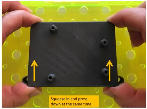
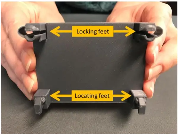 | 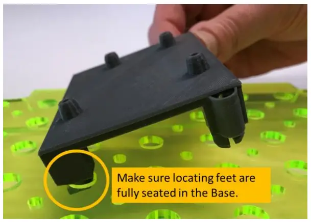 |
| Notice the Feet—There are two different kinds “Locating Feet” are shaped like little shoes. In this photo, they are on the bottom. “Locking Feet” have elliptical springs and look like a pillar with a slit through the middle. Squeeze the locking feet gently to see how the spring works. | Place the Click Keep the locking feet (with the springs) on the side toward you. Tip the Click and insert the locating feet into any two primary holes in the Base. Make sure the locating feet are fully seated in the Base. |
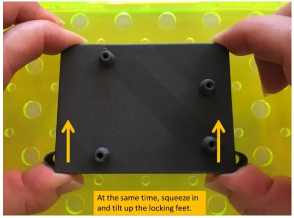
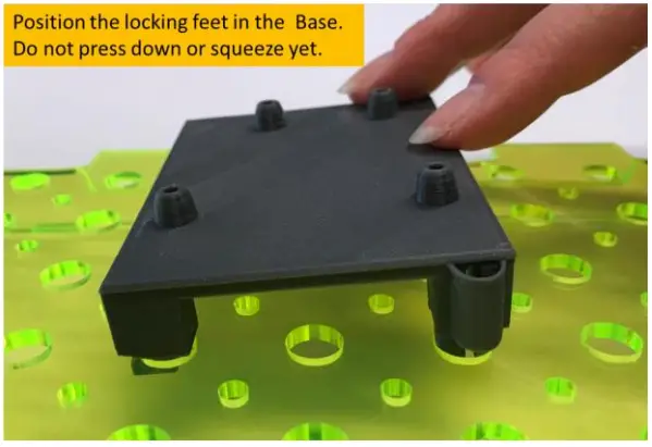 |  |
| No pushing or squeezing yet! Simply set the locking feet down on the holes of the Base. Important: Do not begin squeezing before the locking feet have settled on top of the holes. If you compress the locking feet too early, the Click will resist insertion. | Lock in place USING BOTH HANDS, place your thumbs on the locking feet with your fingers on the locating feet, and gently squeeze together, while pushing down. Once the locking feet drop down into the holes, release the springs. The Click is firmly attached. The Click will stay firmly attached to the Base until you deliberately release it. |
Release Clicks from the Base
The Click will stay firmly attached to the Base until you deliberately release it.
NEVER FORCE the Clicks into or out of the Base.
 | 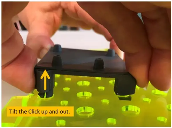 |
| Release the Click—it’s just the opposite of attaching them Turn the Base so that the locking feet of the Click is closest to you. USING BOTH HANDS, place your thumbs on the locking feet with your fingers on the locating feet. Gently squeeze while lifting up with your thumbs to release the locking feet. | Lift the Click Tilt the Click up and out. |
Electronics Mounting Guidelines
FREE 42-page Electronics Mounting Guide and videos at https://phasedock.com/ebook/.
| Item | Guidelines | |
| Electronics with matching Slide™ Adapter • Arduino UNO • Raspberry Pi 2/3 • Raspberry Pi Zero • BeagleBone Black • Jetson Nano • Adafruit Feather, Featherwing or Particle Argon, Boron or Xenon | Use M2.5 x 8mm machine screws to fasten electronics to the raised mounting bosses on the Click/Slide assembly. | 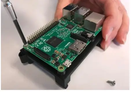 |
| Electronics with matching Slide™ Adapter • Circuit Playground and similar | Use M2.5 x 20mm machine screws and M2.5 hex nuts. Thread the hex nuts onto the screws BEFORE inserting them into the raised mounting bosses. Find the 3 GND (ground) locations on the Circuit Playground. Using machine screws, align the GND holes with the raised bosses on the Slide. Check the alignment of the USB and power ports before tightening the screws. In 2 of the 3 mounting possibilities, the ports are on the diagonal rather than square to the Click. 1. Drive the machine screws firmly into the raised bosses. 2. Tighten the hex nuts securely to the Circuit Playground. 3. Use alligator clips on the machine screws and the rest of the Circuit Playground. 4. If your circuit isn’t working as expected, check to be sure the hex nuts are making good contact with the board. | 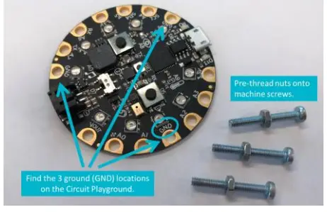 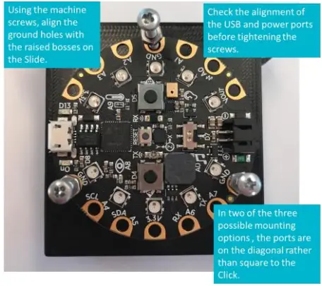 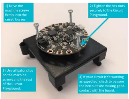 |
| Electronics with mounting holes, but no matching Slide (method 1) Register at www.PhaseDock.com/ contact to be notified when new Click and Slide products are released. VIDEO  | Fasten the electronics directly to an appropriately sized Click* by threading self-tapping screws through the electronics, the tubular standoff, and into the Click platform. Screws may protrude slightly on the underside of the Click but this will not interfere with the functionality of the Click. A power screwdriver makes assembly easier. *CAUTION: Avoid driving screws into the locking feet (red X) on the Click. Video: http://PDK.PhaseDock.com/DirectMount | 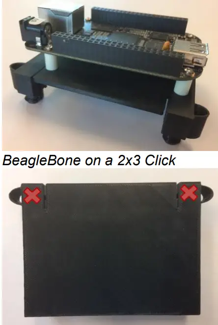 |
| Electronics with mounting holes, but no matching Slide (method 2) | Attach the item directly to the Click without standoffs. At the right, a small speaker and a terminal block are mounted directly to the Click using only self-tapping screws. *CAUTION: Avoid driving screws into the locking feet (red X) on the Click. | 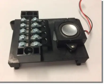 |
| 400-Pt Breadboard | Use mounting tape on the reverse to stick the breadboard directly to a blank 2×3 Click. | 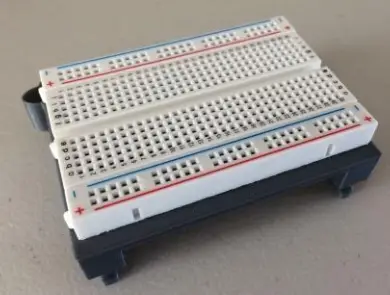 |
| 700-Pt Breadboard | • Option 1) Use mounting tape on the reverse to stick the breadboard directly to a blank 2×5 Click. • Option 2) Acrylic platform with brass hardware; uses secondary matrix in base. | 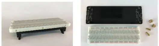 |
| Tower electronics | Use the M2.5 male-female nylon standoffs to layer electronics. | 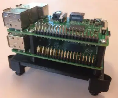 |
| Batteries or items without mounting holes | To attach items that lack mounting holes, one option is to use zip ties. This is an easy way to secure batteries for your project. 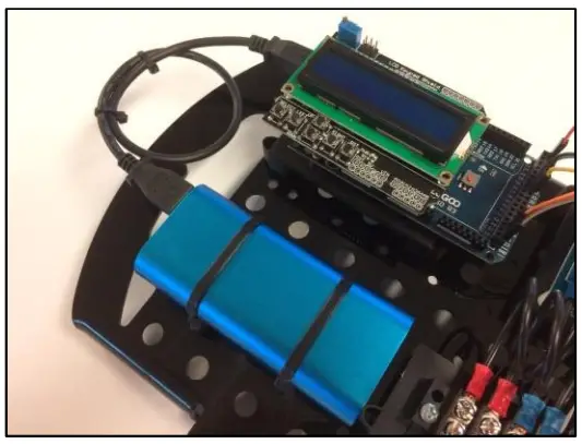 | 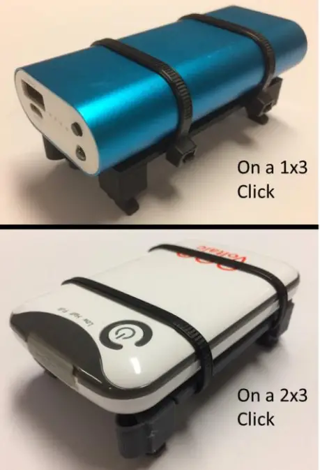 |
| Cable management | Use the 8-32 x 7/16 machine screw and nyloc nut to attach the cable-tie saddle mount (shown here in white) using one of the smaller holes in the Base grid (the “secondary grid”). Attach wires on top or underneath the Base using a small zip tie (provided) or hook-and-loop tie. | 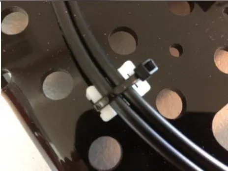 |
FREE Electronics Mounting Guide and videos at https://phasedock.com/ebook/
Click/Slide Assembly*
With hardware in hand and a simple jig, Click/Slide assembly is quick and easy. All the small hardware you need is included in the Hardware Packet that comes with your Universal WorkBench™ Kit. In addition, you will need super glue (cyanoacrylate) and nitrile or latex gloves (recommended). Watch the video at pdk.phasedock.com/Assembly or use the QR Code.

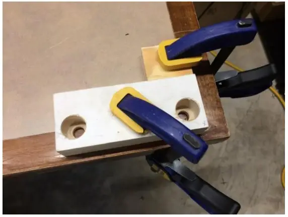
Step 1: Set up a jig (optional)
For easy, precise assembly, make an L-shaped (90°) jig by clamping two straight pieces of scrap wood to a table.
IMPORTANT: The block on the X-axis (right) should be no wider than 2” when you are gluing up 2×3 Clicks or no wider than 1” to glue up 1×3 Clicks.
See Step 7 for reference.
Step 2: Grab the correct Slide*
Check to make sure that the raised mounting bosses on the Slide match the hole-mounting pattern on the electronics.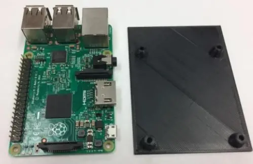
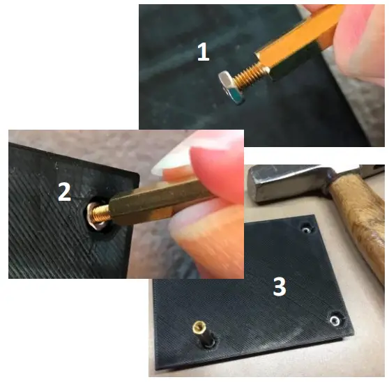
Step 3: Insert M2.5 hex nuts (1)*
Insert four M2.5 hex nuts into the back side of the Slide bosses:
- Thread a hex nut just onto the end of the provided M2.5 x 20 screws for leverage.
- Push the nut firmly into the hex pocket in the boss until it seats.
- A light tap with a hammer may be needed.
- Unthread the screw and repeat for the other three bosses.
*Skip steps 3 & 4 for Click/Slide assembly for Circuit Playground Express and similar boards.
Step 4: Insert M3.0 hex nuts (2)*
Insert four M3.0 hex nuts into the bosses on top of the M2.5 nuts. They should lie level with or slightly below the surface. These larger hex nuts fit loosely and do not need help with insertion.
The M3.0 nuts are spacers only; they prevent the M2.5 nuts from possibly dropping out of position after the assembly is glued up.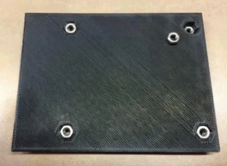
Step 5: Place the Slide into the jig
Place the Slide into the jig with the raised mounting bosses down and hex nuts up and visible.
Always glue the assembly with the Slide on the bottom as shown.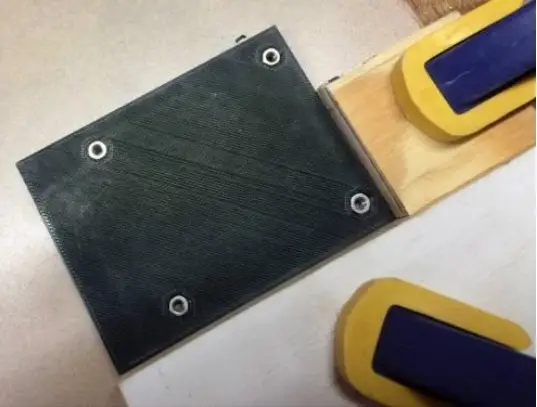
Step 6: Apply super glue to the Click
Gloves are recommended for steps 6 and 7.
Draw a generous bead of super glue (cyanoacrylate) on the top of the CLICK (NOT the Slide) following the pattern shown in blue.
Be careful NOT to glue the corners of the CLICK where the springs are located (red X’s). Your Click will not function properly if the springs are immobilized.
Spread some glue in the middle if desired.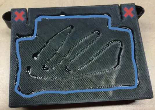
Step 7: Final assembly
Place the glued side of the Click down onto the Slide and press both components firmly into the jig to line up the edges and then press down onto each other to set the glue. Follow the instructions on the glue and hold in this position for the proper set time.
IMPORTANT: Note that the springs on the Clickextend beyond the corner of the jig. If your X-axis block is too wide, the Click will not align correctly with the Slide.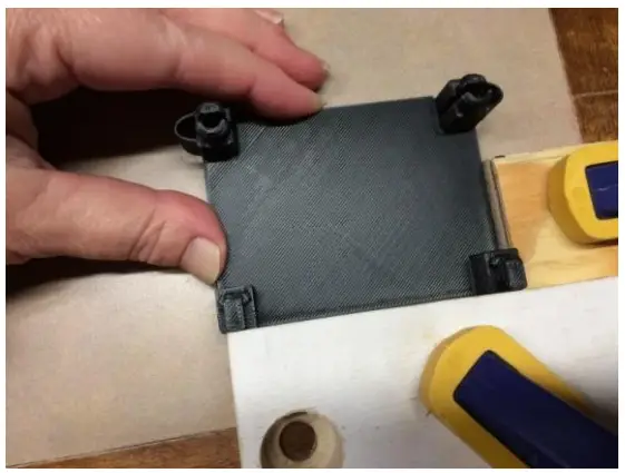
Step 8. Attach electronics
Using the M2.5x8mm machine screws, attach your electronics to the Slide.
Use nylon standoffs for tower projects.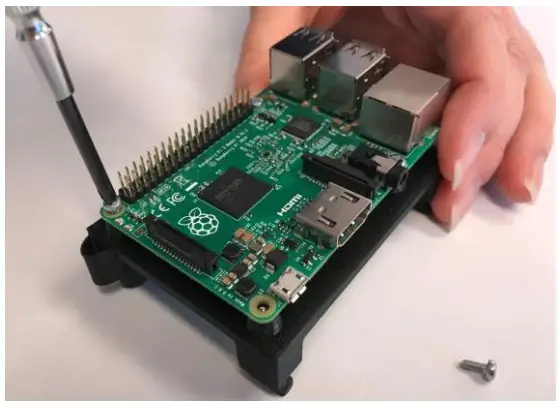 *Skip steps 3 & 4 for Click/Slide assembly for Circuit Playground and similar boards.
Care and Cleaning of the WorkBench Base and Cover
CAUTION – DO NOT USE: Window cleaning fluids (such as Windex), gritty cloths, household scouring compounds (such as Comet), lacquer thinner, benzene, gasoline, strong solvents (such as Goof-Off and others), or anything containing alcohol, acetone, carbon tetrachloride, or ammonia.
DUSTING: Gently use a soft, damp cloth or chamois.
CLEANING: Remove any electronics and use a small quantity of soap and lukewarm water, rinse well with clean water and dry with a soft cotton cloth or chamois.
We recommend a product called Brillianize Acrylic Cleaner for cleaning acrylic, glass, and hard shiny surfaces. It provides an anti-static coating, helps repel dust, and is non-toxic – alcohol and ammonia-free. Brillianize is available online and from home improvement and big box stores.
To remove stickiness left by adhesive tape, you can use citrus-based cleaners (such as Goo Gone); however, we recommend you remove the electronics to enable soap and water follow-up to the oily cleaners.
FOR SCRATCH REMOVAL: After years of use and cleaning, the WorkBench Base and Cover may develop fine surface scratches. We recommend using NOVUS 2 Fine Scratch Remover with a 100% cotton cloth to buff out fine scratches. Novus 2 is available online and from home improvement and big box stores.
2022/05/15 Guide to Using the Universal WorkBench™ Project Development Kit from Phase Dock


