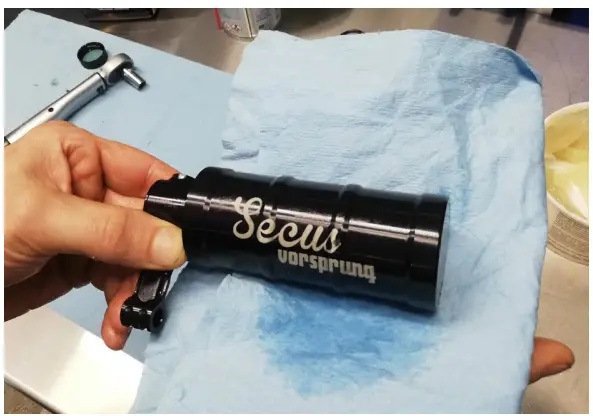
![]() Secus
Secus
FORK AIR SPRING
UPGRADE KIT
STANDARD SERVICE PROCEDURE –DYNAMIC SEALS
REVISION A
User Manual
FORK AIR Spring Upgrade Kit
 WARNING!
VORSPRUNG products should be installed and serviced by a trained bicycle service technician, in accordance with both VORSPRUNG and original manufacturers’ specifications. The Secus is a complex system. If you have any doubt whether or not you can properly service your suspension product, or you have not performed this kind of work before, then please DO NOT attempt it. Improperly serviced products can fail, causing the rider to lose control resulting in SERIOUS INJURY OR DEATH. That’s not a joke. Don’t mess around with it if you don’t know what you’re doing, because the best-case scenario is usually that you damage something in the process. Do not perform any kind of service on your suspension whilst drunk, high or stupid. We accept no responsibility nor liability for component damage or failure of any description in the case of self-installed units.
Make sure the air spring is fully depressurized before opening or removing the Secus. Never open a pressurized system.
TOOLS REQUIRED
NOTE: Do not proceed unless you have the following tools and supplies on hand.
- 8mm socket
- 11mm socket
- Torque wrench
- Slickoleum (Slick Honey) grease
- Float fluid or 20wt oil
There are 3 main sections to servicing your Secus:
PART 1 – Removing the Secus from your fork
PART 2 – Disassembly of the Secus & replacing dynamic seals
PART 3 – Installing your Secus
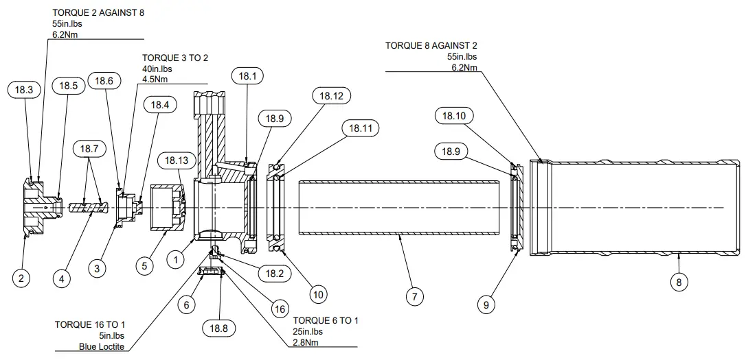
DRAWING 1: EXPLODED VIEW

| Parts List | ||
| Item | Qty | Part Number |
| 1 | 1 | 13-08-1-01 (Valve Housing) |
| 2 | 1 | 13-08-1-02 (Valve Outer) |
| 3 | 1 | 13-08-1-03 (Valve Inner) |
| 4 | 1 | 13-08-1-04 (Eq Button) |
| 5 | 1 | 13-08-1-05 (Valve Spool) |
| 6 | 1 | 13-08-1-06 (Housing Plug) |
| 7 | 1 | 13-08-1-07 (Res Inner Tube) |
| 8 | 1 | 13-08-1-08 (Res Outer Tube) |
| 9 | 1 | 13-08-1-09 (Res End Cap) |
| 10 | 1 | 13-08-1-10 (IFP) |
| 16 | 1 | MMC-92855A301 |
| 18 | 1 | Secus 0-Rings |
| 18. | 1 | 37.82×1.78mm (2-029) |
| 18. | 1 | 3.00×1.00mm |
| 18. | 1 | 20.35×1.78mm (2-019) |
| 18. | 1 | 4.00×1.00mm |
| 19. | 1 | 7.00×1.00mm |
| 19. | 1 | 16.00×1.00mm |
| 19. | 2 | 2.00×1.00mm |
| 19. | 1 | 9.50×1.00mm |
| 19. | 2 | 25.12×1.78mm (2-022) |
| 18.10 | 1 | 34.65×1.78mm (2-028) |
| 18. | 1 | 25.07×2.62mm (2-120) |
| 18. | 1 | 34.59×2.62mm (2-126) |
| 18. | 1 | 3.68×1.78mm (2-007) |
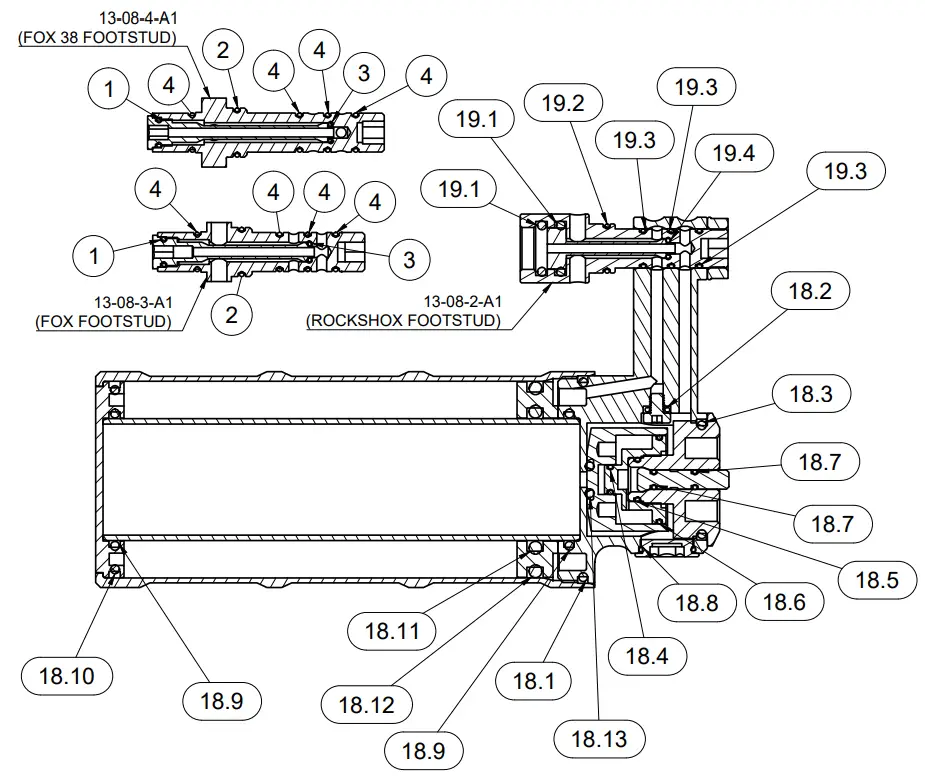
DRAWING 2: SEAL SCHEDULE
| Parts List | ||
| Item | Qty | Part Number |
| 18 | 1 | Secus 0-Rings |
| 18. | 1 | 37.82×1.78mm (2-029) |
| 18. | 1 | 3.00×1.00mm |
| 18. | 1 | 20.35×1.78mm (2-019) |
| 18. | 1 | 4.00×1.00mm |
| 19. | 1 | 7.00×1.00mm |
| 19. | 1 | 16.00×1.00mm |
| 19. | 2 | 2.00×1.00mm |
| 19. | 1 | 9.50×1.00mm |
| 19. | 2 | 25.12×1.78mm (2-022) |
| 18.10 | 1 | 34.65×1.78mm (2-028) |
| 18. | 1 | 25.07×2.62mm (2-120) |
| 18. | 1 | 34.59×2.62mm (2-126) |
| 18. | 1 | 3.68×1.78mm (2-007) |
| 19 | 1 | RS Footstud 0-Rings |
| 19. | 2 | 7.65×1.78mm (2-011) |
| 19. | 1 | 8.00×1.00mm |
| 19. | 3 | 6.00×1.00mm |
| 19. | 1 | 2.50×1.00mm |
| Parts List | ||
| Item | Qty | Part Number |
| 1 | 1 | 4.00×1.00mm |
| 2 | 1 | 8.00×1.00mm |
| 3 | 1 | 2.50×1.00mm |
| 4 | 4 | 6.00×1.00mm |
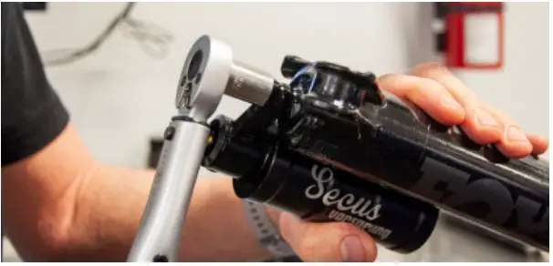
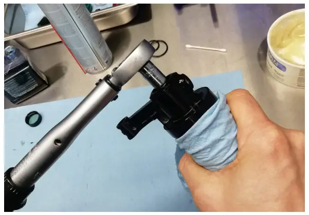
PART 1 – DEPRESSURIZATION & SECUS REMOVAL
1.0 Depressurize your fork: ensure the gold button on the Secus is held down while releasing the air slowly from the top cap.
This will ensure the negative chamber is fully discharged while depressurizing.
If the fork sucks down more than 20mm while depressurizing, that means the air piston has come past the equalization ports too fast and the air is still trapped in the negative chamber, unable to equalize and escape via the positive chamber. In this case, re-inflate the fork (or forcibly extend it by placing your foot on the wheel and pulling on the bars), re-equalize it, then let the air out more slowly.
WARNING: You must depressurize the fork fully if you wish to take the lowers off.
Do not remove the lowers without depressurizing the air spring.
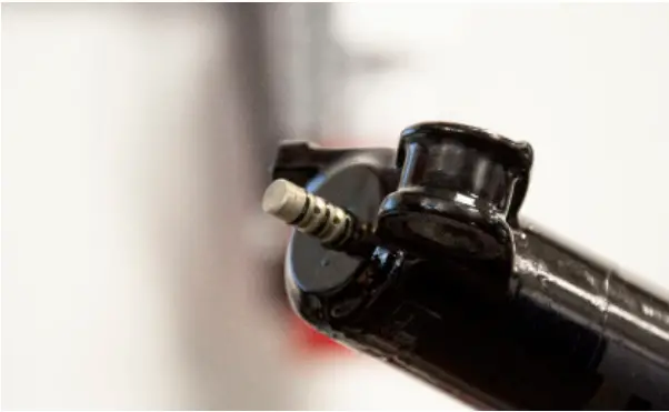
1.1 Undo the footnut. Remove Secus from the footing stud.
1.2 Perform lower leg removal & service as per manufacturer’s instructions.
Now is the time to service the standard air spring components too if desired.
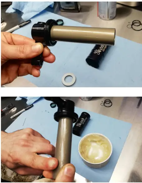
1.3 Replace the 1x larger (8.00mm ID) o-ring before reinstalling the lower legs.
After reinstalling the lower legs, replace
3x smaller (6.00mm ID)
o-rings on the footstud.
All are 1.00mm cross-sections.
PART 2 – SECUS SERVICE
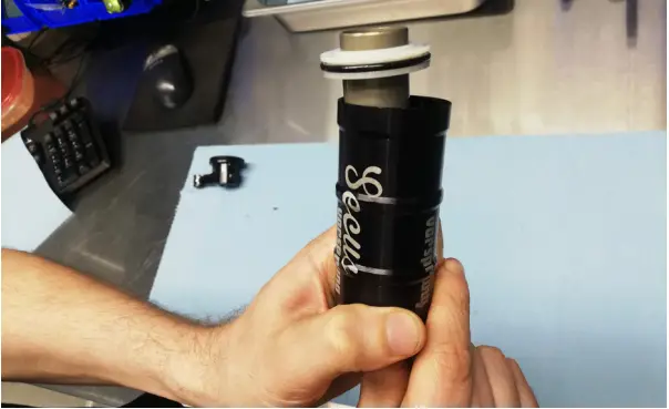
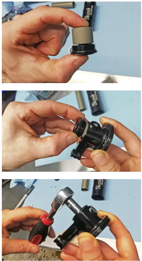
2.0 PUSH THE GOLD BUTTON to release any air that may still be left in the unit. The button should stay depressed if there is no pressure inside.
Loosen the Valve Outer from Valve Housing (1) with an 8mm socket to release any air that may still be left in the unit.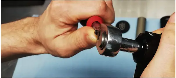
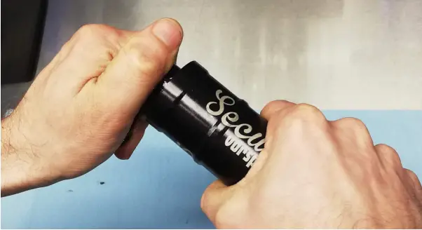
Undo the Reservoir Outer from the Valve
Housing by grasping firmly and twisting.
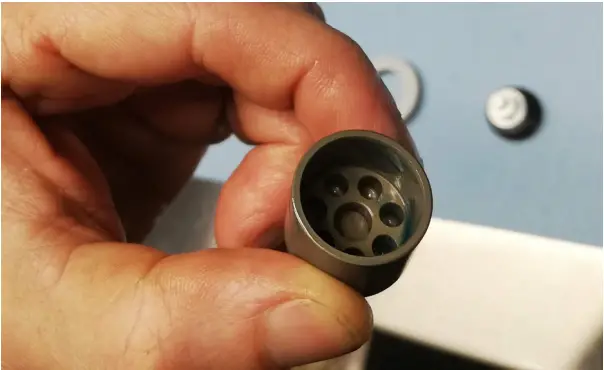
2.1 Remove Inner Tube and IFP by pushing
Reservoir End Cap in until you can grasp one or both of the IFP and Inner Tube.
2.2 The Secus standard service procedure typically entails the replacement of dynamic (moving) seals and foot stud outer seals only.
However, all other visible static (non-moving) o-rings should be inspected during the service and replaced if leaking, damaged, or contaminated with dirt or debris. Refer to Drawing 2: Seal Schedule on Page 4 of this manual for seal specifications if required.
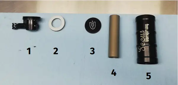
You will now have these parts:
- Valve Housing
- IFP
- Reservoir Cap
- Inner Tube
- Reservoir Outer
2.3 Undo the Valve Outer from Valve Housing (1) with an 8mm socket.
Detach Valve Spool from Valve Outer by pulling, to expose the Valve Inner.
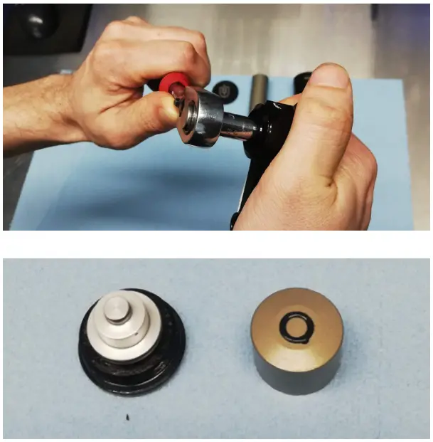
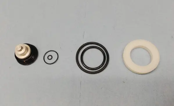
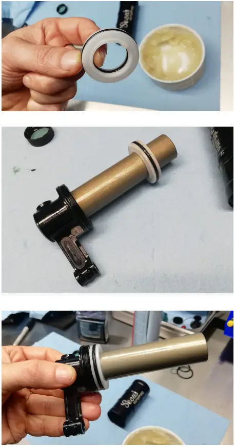
2.4 Remove o-rings from IFP and Valve Inner.
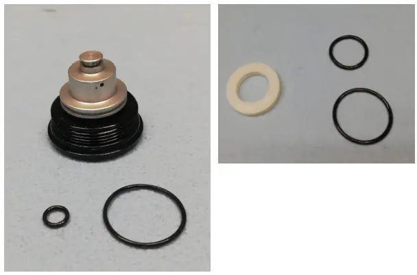
2.5 Replace seals on Valve Inner and IFP.
2.6 Apply oil (Float fluid or 20wt fork oil) liberally to the o-rings on the Valve Inner. Also, lubricate the inner surface of the Valve Spool (do not get any excess oil in the center hole/groove).
2.7 Assemble Valve Spool back onto Valve Inner by pushing down firmly. It will push back out slightly – this is normal.
Assemble Valve Outer back into Valve Housing.
Note: this does not need to be done up tight yet.
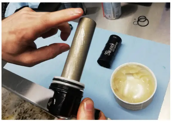
2.8 Assemble Reservoir Inner Tube to Valve Housing.
Apply Slick Honey/Slickoleum grease liberally to Inner Tube
2.9 Apply Slickoleum/Slick Honey to IFP seals & assemble onto Inner Tube with the step side down.
Push IFP all the way to the end of the tube until it contacts the Valve Housing.
2.10 Apply slick honey to another side of the Inner Tube.
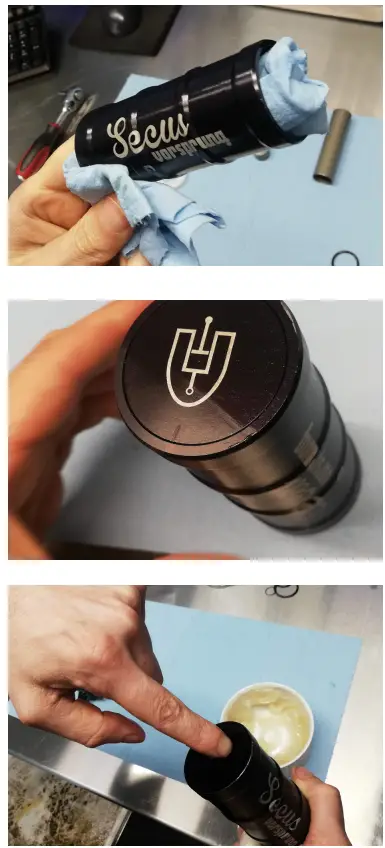
2.11 Thoroughly clean Reservoir Outer. Inspect for damage.
Insert Reservoir End Cap into Reservoir Outer. Push to the far end, until seated.
Apply Slickoleum/Slick Honey grease to the interior surface of the Reservoir Outer.
2.12 Thread Reservoir Outer to Valve Housing by hand. Do not tighten fully yet.
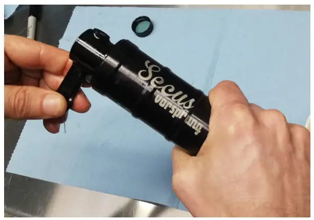
2.13 Clean Outer Can with suspension clean, this will allow for better grip.
USE A TORQUE WRENCH to torque the Valve Outer against the Reservoir Outer to 55lbs/in or 6.2Nm.
Reservoir End Cap logo alignment is not critical to function. However, should you wish to align it, you may need to re-loosen the Reservoir Outer, rotate the end cap using pressure from two fingers, and then re-torque the Reservoir Outer against the Valve Outer.
This may require a few adjustments to get aligned to your liking.
SECUS SERVICE IS NOW COMPLETE.
PART 3 – SECUS INSTALLATION
PLEASE SEE PART 2 & 3 OF RELEVANT SECUS INSTALL MANUAL AT
www.vorsprungsuspension.com
Questions?
[email protected]
www.vorsprungsuspension.com


